![]()
![]()
Apply Elevations to Geometry from ASCII module updates source and/or receiver elevation values in seismic geometry using elevation information provided in an external ASCII text file. The module matches records from the input file to existing seismic geometry based on line and point identifiers and applies the elevation values directly to trace headers.
This approach allows elevation corrections or survey updates to be applied without reloading seismic data or rebuilding geometry from scratch.
When to use this module?
Use this module when:
•Elevation information becomes available after geometry loading
•Surveyed elevations need to replace placeholder or incorrect values
•Elevation corrections are required prior to statics or imaging
How it works?
•Reads elevation records from the specified ASCII file
•Applies coordinate and elevation scaling as required
•Matches file records to seismic geometry using line and point numbers
•Updates elevation headers for selected targets (sources and/or receivers)
![]() Only elevation values are modified.
Only elevation values are modified.
Supported input files:
•Tab-delimited text files
•Space-delimited (formatted) text files
•Comma-separated values (CSV) files
The input file must contain at least line, point number, and elevation columns.
Output:
•Source and/or receiver elevation headers are updated in place
•No new traces or geometry objects are created
•Existing seismic data samples are not modified
![]()
![]()
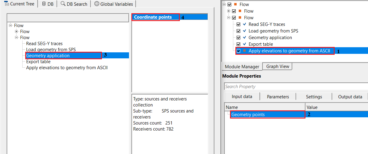
Geometry points - these are typically the coordinate points which are used to assign the elevation information from the input elevation file. Connect/reference to coordinates and locations of the input trace headers. This is usually from "Load geometry from SPS" or Load geometry from ASCII, Load geometry from P190 etc modules.
Connect this input to the geometry output of a geometry-loading module such as Load Geometry from SPS, Load Geometry from ASCII, or Load Geometry from P190. The module reads the source and receiver coordinate lists from this connection and matches each station to elevation records in the ASCII file using the line name and shotpoint (SP) number as keys. Both the source and receiver vectors must be valid before the module can execute.
![]()
![]()
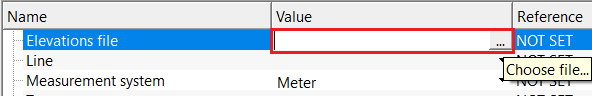
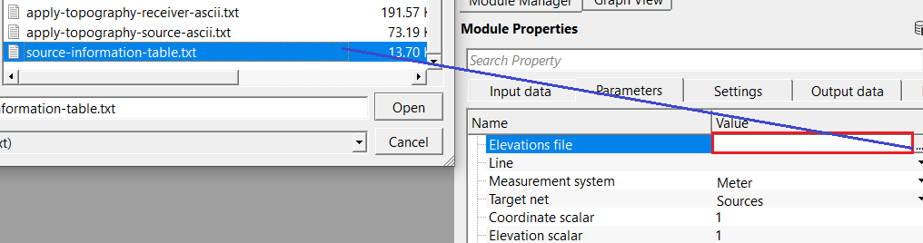
Elevations file - specifies the ASCII text file & location containing elevation data to be applied to seismic geometry.
Browse to or type the full path of the elevation ASCII file (extension .txt). This file must contain at minimum one column for the shotpoint (SP) identifier and one column for the elevation value. Additional columns for line name, X, and Y coordinates can be included for reference or matching purposes. Once a file is selected, the module automatically reads the file header and populates the column-selection drop-down menus in the File read parameters group.
Line - specifies the seismic line name used to match elevation records to geometry. Required when multiple lines are present.
After the elevation file is loaded, this drop-down list is automatically populated with all line names found in the file. Select the specific line whose elevation data you wish to preview or apply. This selection also controls which elevation profile is displayed in the QC graphs (Sources elevations graph and Receivers elevations graph).
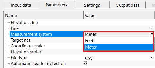
Measurement system { Feet, Meter } - specifies the unit system used for elevation values in the input file. By default, Meter.
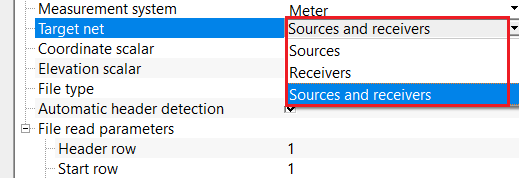
Target net { Sources, Receivers, Sources and receivers } - selects which geometry objects are updated using the elevation file. Select the options from the drop down menu.
Choose Sources to update only source (shot) point elevations, Receivers to update only receiver (geophone) elevations, or Sources and receivers to update both simultaneously. By default, Sources and receivers. The geometry vectors not targeted by this selection are passed through unchanged to the output.
Coordinate scalar - scaling factor applied to X and Y coordinates read from the file before matching. Used to convert integer or scaled coordinates to real values. By default, 1.
Use this parameter when the X and Y values in the elevation file are stored in a scaled integer form (for example, multiplied by 10 or 100 to avoid decimal points). Set this scalar to the divisor needed to recover real-world coordinate values. For example, if coordinates in the file are stored as integers with an implicit scale of 1/10, set this value to 10. Leave at the default value of 1 if no scaling is required.
Elevation scalar - scaling factor applied to elevation values read from the file. Used to convert stored integer elevations to real units. By default, 1.
Use this parameter when the elevation values in the file are stored in a scaled integer form. Set this scalar to the divisor required to recover true elevation values in the units specified by the Measurement system parameter. For example, if elevations are stored in centimetres but should be expressed in metres, set this value to 100. Leave at the default value of 1 if no scaling is required.
Automatic header detection - this option automatically detects the input elevation file headers. By default, TRUE (Checked).
When enabled, the module reads the first row of the elevation file and uses the column names found there to automatically populate the column-selection lists in the File read parameters group. This is the recommended setting for most standard ASCII elevation files. Disable this option only if the file has no header row, in which case you must assign the column positions manually using the File type - Manual mode.
File read parameters - specify the input elevation file read parameters
This group of parameters controls how the module interprets the structure of the ASCII elevation file. The parameters available in this group depend on the selected File type: for delimited formats (Tab, Space, CSV), you select named columns from the file header; for Manual format, you specify the exact character positions for each field.
Header row - specify the header row position. By default, 1.
Enter the row number in the ASCII file that contains the column names. The module reads the names from this row and uses them to populate the column-selection drop-down lists. Rows above this number are skipped. Valid range: 1 to 1,000,000. In most standard ASCII files, the header is on row 1.
Start row - specify the start row position. By default, 1.
Enter the row number where actual data records begin. Rows between the header row and this row are treated as additional comment or description lines and are ignored. In most files, data begins immediately after the header, so this value equals the header row number plus one. Valid range: 0 to 1,000,000.
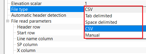
File type { Tab delimited, Space delimited, CSV, Manual } - specifies the delimiter format used in the input elevation file. Supported formats include Tab delimited, Space delimited, CSV, and Manual. Select the option from the drop down menu and provide the respective parameter.
File type - Tab delimited - indicates that columns in the elevation file are separated by tab characters.
Line name column - specifies the column containing the seismic line identifier in the input file.
SP column - specifies the column name containing the source or receiver point number used for matching geometry.
X column - specifies the column name containing the X coordinate value in the elevation file.
Y column - specifies the column name containing the Y coordinate value in the elevation file.
Elevation column - specifies the column name containing the elevation value to be applied to geometry.
File type - Space delimited - indicates that columns in the elevation file are separated by space characters.
File type - CSV - indicates that columns in the elevation file are separated by comma characters.
File type - Manual - indicates that columns in the elevation file are not in any standard format. The user has to provide the respective column positions.
Line name position - specify the line name position from the input elevation file.
SP position - specify the source/receiver point number position from the input elevation file.
X position - specify the X coordinate position from the input elevation file.
Y position - specify the Y coordinate position from the input elevation file.
Elevation position - specify the elevation value position from the input elevation file.
![]()
![]()
Skip - By default, FALSE(Unchecked). This option helps to bypass the module from the workflow.
![]()
![]()
Geometry points out - outputs the updated geometry point vectors containing the newly assigned elevation values.
This output carries the updated source and receiver geometry, with elevation values replaced by those read from the ASCII file. Connect this output to downstream geometry or statics modules that require surface elevation information. Geometry objects not targeted by the Target net setting are passed through without modification.
Elevations table - outputs a tabular view of all elevation records read from the ASCII file.
Displays all records parsed from the input elevation file as a table with columns: Line name, SP, X, Y, and Elevation. Use this QC table to verify that the file was read correctly and that elevation values are in the expected range before examining the updated geometry. All lines present in the file are included, not just the line selected in the Line parameter.
Sources geometry table output - outputs a tabular view of the updated source geometry with elevation values applied.
Displays the complete source (shot) point geometry after elevation assignment. Columns include Line name, SP, X, Y, and updated Elevation. Compare this table with the Sources geometry table input to confirm that elevations have been correctly updated for all source stations. Stations for which no matching elevation record was found in the ASCII file retain their original elevation value.
Receivers geometry table output - outputs a tabular view of the updated receiver geometry with elevation values applied.
Displays the complete receiver (geophone) point geometry after elevation assignment. Columns include Line name, SP, X, Y, and updated Elevation. Use this table alongside the receivers elevation graph (before/after) to perform a full QC of the elevation update for the receiver network.
There is no information available for this module.
![]()
![]()
In this example workflow, we are updating the elevation information where elevation information was not present in the navigation data.
We've to connect/reference to coordinates points. In the parameters tab, we've to provide the input elevation file in ASCII format. Choose the correct file type and measurement units from the drop down menu. In case the file format is not a standard format, the user should provide the column positions manually.
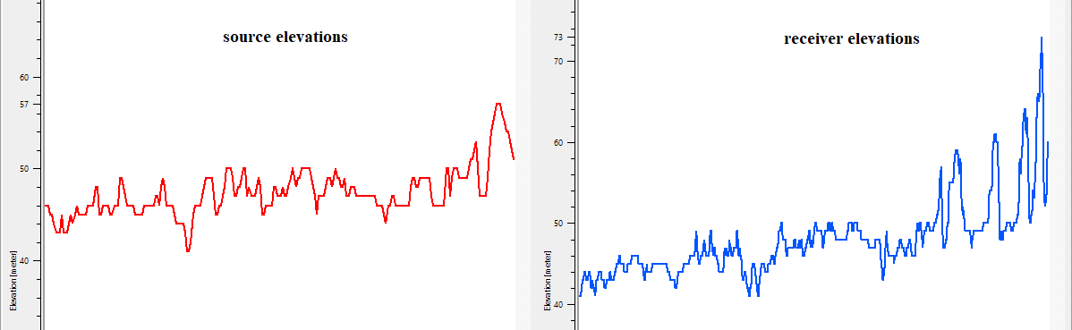
Adjust the parameters as per the input data requirements and execute the module. QC the elevations before and after.
![]()
![]()
There are no action items available for this module so the user can ignore it.
![]()
![]()
YouTube video lesson, click here to open [VIDEO IN PROCESS...]
![]()
![]()
Yilmaz. O., 1987, Seismic data processing: Society of Exploration Geophysicist
 * * * If you have any questions, please send an e-mail to: support@geomage.com * * *