Description
Data Enhance - 2D CO-MF produces enhanced pre-stack seismic data by applying the Common Offset MultiFocusing (CO-MF) technique. The module reads optimal MultiFocusing parameters from a pre-computed CO-MF database and uses those parameters to perform a targeted partial stack of neighboring traces around each output location. This partial summation coherently adds traces that share similar wavefield geometry, improving the signal-to-noise ratio while preserving pre-stack offset information.
A key advantage of this approach is that the MultiFocusing time-correction formula does not require CMP symmetry. This means that the module can compute valid time corrections for imaging points that fall anywhere within the acquisition aperture, making it suitable for data regularization as well as enhancement. You can use this module to fill in missing offset classes, interpolate to a new output geometry, or simply reduce noise on existing gathers.
The module requires an existing 2D CO-MF parameter database produced by the Engine - 2D CO-MF module. The pre-stack seismic data to be enhanced is supplied as a SEG-Y data handle together with raw and virtual CMP gather index vectors that describe the input and output geometries, respectively.
Input data
Storage file
Path to the 2D CO-MF parameter database file (.kdb extension). This database is produced by the Engine - 2D CO-MF module and contains the optimized MultiFocusing wavefront parameters for each imaging point and offset class. The module reads the geometry, time-step, and number of samples from this file — these must be compatible with the input SEG-Y data. This input is mandatory.
(!!! TEST !!!) File with polygons
Optional path to a polygon file (.polygon extension) defining spatial areas within which the data enhancement will be restricted. Only output bins that fall inside the specified polygons will be processed. If left empty, enhancement is applied over the full calculation area. This input is marked as a test feature and may not be required for standard workflows.
Output file name
Path and filename for the output SEG-Y file (.gsd extension) that will contain the enhanced pre-stack data. The file will be written using the mode specified by the Write mode parameter — either created fresh (Direct) or appended to an existing file (Append). This input is mandatory.
SEG-Y data handle
Connection to the input pre-stack seismic dataset. This is the raw field data (or previously processed gathers) that will be enhanced by the CO-MF partial summation. The sample count and time step of this data must not exceed those stored in the CO-MF database. Connect this to the SEG-Y output of a preceding data-reading module.
GRawGatherIndexVectorItem
The CMP gather index describing the actual (raw) acquisition geometry of the input data. This index tells the module which real traces exist and where their CMP midpoints are located. It must be a valid 2D CMP-sorted index. Connect this to the raw gather index output of your geometry assignment module.
GVirtualGatherIndexVectorItem
The CMP gather index describing the desired output geometry — the set of imaging points for which enhanced traces will be created. This can differ from the raw geometry, allowing the module to produce regularized or interpolated output. For a simple enhancement without re-binning, this is typically the same as the raw gather index. Must be a valid 2D CMP-sorted index.
G3DPickingItem
An optional velocity picking constraint used during data enhancement. When connected, this picking item restricts the CO-MF time corrections to a corridor around the picked velocities, preventing the partial stack from summing coherently along erroneous moveout paths. Use this to improve enhancement quality in areas with complex velocity structure or poor signal-to-noise ratio.
V0 Map
An optional 2D map (grid) supplying a spatially variable near-surface velocity (V0) to be used in the MultiFocusing time-correction calculations. When provided, the V0 value at each output bin location is read from this map and used to refine the datum-shift correction. If not connected, the V0 value stored in the CO-MF database is used instead.
Parameters
EnhanceProcedureType
Selects the operation mode. Options:
Enhance (default) — Improves signal-to-noise ratio at existing output geometry positions using CO-MF partial stacking. Use this mode when the output bins already have real data and the goal is noise suppression.
Interpolation — Creates synthetic traces at output positions that may not exist in the original acquisition. Use this mode for data regularization, offset interpolation, or filling gaps in coverage.
Create NMO corrected gathers
When enabled, the output enhanced traces are delivered in NMO-corrected form (reflection events flattened to zero time). This is useful when the enhanced data will be fed directly into a stacking or AVO analysis step that expects NMO-corrected gathers. Default: off. Leave disabled if the output will be used for further pre-stack processing that requires offset-dependent moveout to be intact.
MF emulation mute
When enabled, the module applies a mute based on the MultiFocusing emulation criteria, suppressing traces or time samples that would be unreliably enhanced due to insufficient wavefield coverage. Default: off. Enable this option to avoid artifacts at the edges of the acquisition aperture or in poorly illuminated zones.
Image creation parameters
A parameter group controlling how MultiFocusing wavefront contributions are selected and combined during the partial stacking. These settings determine which MF image waves are accepted and how they are weighted.
Directions (integer, default 1) — Number of independent dip directions to consider during stacking. Increasing this value allows the module to follow more complex wavefront geometries, but increases computation time.
From angle / To angle (degrees, defaults -90 / +90) — Angular range of dip directions to include. Contributions from wavefronts arriving outside this angular window are excluded. Narrow this range to suppress noise from specific directions.
SN enhance (boolean, default off) — Activates additional signal-to-noise weighting during the partial stack. When enabled, wavefront contributions are weighted by their semblance coherence so that high-coherence contributions are favored over noisy ones.
Correlation threshold (%, default 10%) — Minimum coherence (semblance) value required for a trace contribution to be included in the partial stack. Contributions with coherence below this threshold are rejected. Raise this value to be more selective; lower it to include more data in areas of weak coherence.
Min angle distance selection (integer, default 1) — Minimum angular separation (in index units) between accepted wavefront directions. This prevents very similar dip solutions from being double-counted.
Min radius distance selection (integer, default 100) — Minimum spatial radius (in index units) between accepted wavefront solutions. Works together with the angle distance criterion to ensure diversity among the selected MF solutions.
Mute type
Selects how the MF mute aperture is defined for the partial stacking. Two options are available:
•Use mute factor — A single constant mute factor value is applied uniformly to all output traces. The value is specified in the MuteFactor parameter below. Use this option for simple, uniform muting.
•Use mute function — The mute function stored in the CO-MF database (the same function used during the MF parameter search) is retrieved and applied. This ensures the enhancement is consistent with the original MF engine settings and is the recommended option for production workflows.
•
MuteFactor
The constant mute factor value used when Mute type is set to Use mute factor. This controls the maximum time-shift (in ms) allowed when searching for traces to include in the partial stack. Default: 1000 ms. A larger value broadens the aperture of the summation; a smaller value makes it more selective. This parameter has no effect when Use mute function is selected.
CO aperture mode
Defines how the common-offset aperture is measured when selecting contributing traces. Options:
XY aperture (default) — The aperture is defined as a spatial distance in the X-Y plane. The Max Distance To MF CO Trace parameter is interpreted as a distance in metres.
Offset aperture — The aperture is defined as a difference in source-receiver offset. The Max Distance To MF CO Trace parameter is interpreted as a maximum offset difference in metres. Use this mode when working with data organized by offset class.
Kill empty traces
When enabled, output bins for which no contributing traces could be found (resulting in a zero-amplitude trace) are omitted from the output file entirely rather than written as blank traces. Default: off. Enable this option to reduce output file size when working with sparse geometries or large interpolation grids.
Distance For Trace Selection
A parameter group containing all distance-based selection criteria for both the MF parameter lookup and the raw seismic data retrieval. The sub-parameters are organized into two sub-groups: MF Trace Selection and Raw Data.
MF Trace Selection
Controls which CO-MF parameter sets from the database are considered when computing the time correction for a given output trace. Three sub-parameters are available:
Max distance to MF CMP (m, default 50 m, max 2000 m) — Maximum horizontal distance from the output CMP location to the nearest MF imaging point in the database. Only MF parameter sets whose imaging point falls within this radius are used for the enhancement of that output trace. A small value makes the parameter lookup very local; increase it when the MF database is coarsely sampled relative to the output geometry.
Max distance to MF CO trace (m, default 1000 m, max 100000 m) — Maximum difference (in metres) between the offset of the output trace and the CO-MF offset class from which parameters are taken. Interpreted as an XY distance or an offset difference depending on the CO aperture mode setting. Increase this value when the CO-MF database offset classes are widely spaced.
Abs offset to find MFCO trace (boolean, default on) — When enabled, the offset matching between the output trace and the CO-MF database uses the absolute value of offset. This is appropriate for 2D datasets where negative and positive offsets represent the same physical acquisition geometry. Disable this only if your data uses signed offsets with a specific directional meaning.
Max Distance To MF CO Trace
Maximum difference in offset (m) between the output trace being enhanced and the CO-MF offset class in the database from which the MultiFocusing parameters are retrieved. Only CO-MF parameter sets within this offset distance are used to compute the time correction for the output trace. Default: 1000 m. See also the CO aperture mode parameter for how the distance measure is interpreted.
Raw Data
Controls which real seismic traces from the input data are selected for inclusion in the partial stack at each output location. Trace selection operates in two sequential stages: a CMP-domain search (stage 1) followed by a source-receiver distance filter (stage 2). Sub-parameters:
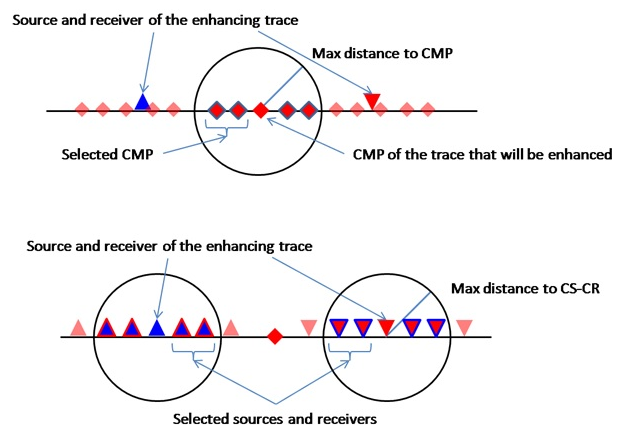
Max Distance To CMP
Maximum horizontal distance (m) between the CMP location of the output trace and the CMP location of candidate input traces (stage 1 of raw data selection). Default: 150 m. Increase this value to draw from a wider spatial aperture of real traces during the partial stack, which can improve results in areas of sparse coverage but may reduce lateral resolution.
•Maximum distance from CMP location of the enhanced trace to the CMP that will be used for partial summation (first stage of trace selection)
Max Distance To CS-CR
Maximum distance (m) from the source and receiver positions of the output trace to the source and receiver positions of candidate input traces (stage 2 of raw data selection). Default: 150 m. After the CMP-domain filter (stage 1), this parameter refines the selection by requiring that the actual source and receiver positions are also close to those of the output trace. This helps maintain offset accuracy in the partial stack.
•Maximum distance from source and receiver of the enhancing trace to the source-receivers that will be used in partial summation (second stage of trace selection)
Symmetrical aperture
When enabled, the source-receiver selection (stage 2 of raw data selection) is performed by requiring that each candidate source is within Max Distance To CS-CR of the output source AND each candidate receiver is within the distance of the output receiver (CS-CS AND CR-CR search mode). When disabled, only the source distance or only the receiver distance needs to satisfy the criterion. Default: off. Enable for stricter, more physically consistent trace selection.
Use dynamic window
When enabled, the interpolation time window starts at zero and is dynamically expanded until the first non-zero contribution is found, up to the maximum length set by Interpolation window length. This avoids applying a fixed-length window in areas where contributions arrive only at late times, leading to a more adaptive and accurate summation. Default: on. Disable only when a fixed window length is required for consistency across all output bins.
Interpolation window length
Length of the time window (in seconds) over which contributing traces are summed to produce each output sample. Default: 0.010 s (10 ms). A longer window collects more contributions and increases smoothing; a shorter window is more selective and preserves higher frequencies. Set this value to approximately half the dominant period of the data as a starting point, then adjust based on the desired output frequency content.
Stabilizations window length
Length of the stabilization time window (in seconds) applied to the denominator of the partial stack normalization to prevent division-by-zero instabilities where the fold is low. Default: 0.010 s (10 ms). Increase this value if the output shows numerical artifacts or ringing in low-fold areas; decrease it if the stabilization is over-smoothing the output amplitudes.
Write mode
Controls how the output SEG-Y file is opened for writing. Options:
Direct (default) — Creates a new output file, overwriting any existing file at the specified path.
Append — Adds the enhanced traces to the end of an existing output file. Use this mode when processing the data in segments (for example, over separate calculation areas) and combining results into a single file. For more details on SEG-Y output options, see the Save SEG-Y module documentation.
Calculation area
A parameter group that limits the enhancement to a subset of the output geometry bins. This is useful for testing parameters on a small section of the line, or for dividing a large dataset into segments for parallel processing. When both limits are set to -1, the full geometry is processed.
First bin to calc(-1 no limit)
Sequence number (1-based index) of the first output bin to process. Set to -1 (default) to begin from the first bin in the output geometry. Use a positive integer to skip bins at the start of the line — for example, when reprocessing a specific segment or appending to a previously generated output file.
Last bin to calc(-1 no limit)
Sequence number (1-based index) of the last output bin to process. Set to -1 (default) to process through the last bin in the output geometry. Use a positive integer to stop processing before the end of the line — for example, when processing the data in overlapping segments or testing on a limited area.