Extending the 2D Bin grid
![]()
![]()
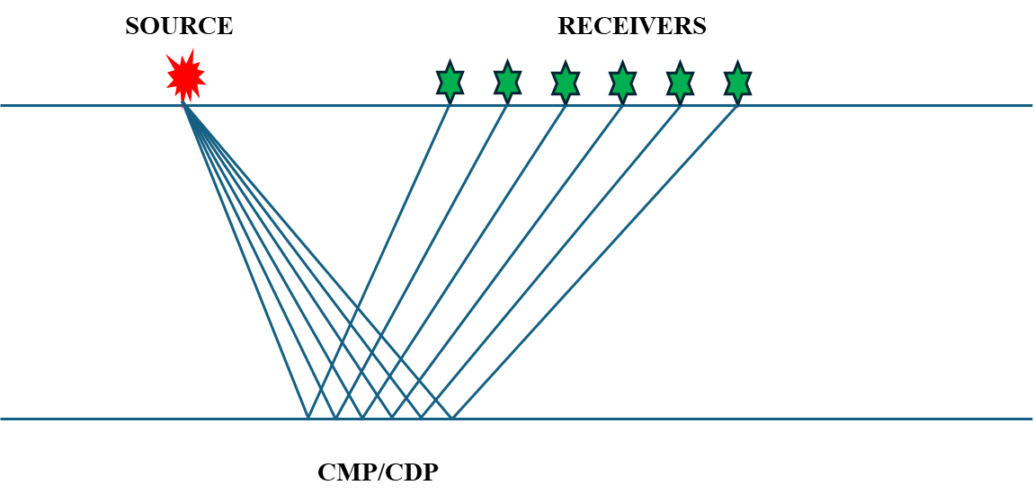
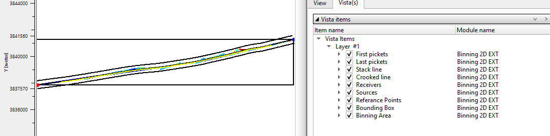
This module creates the sub-surface geometry of 2D seismic data where traces are grouped together by their sub-surface positions into common midpoints (CMP) that are also termed common depth points (CDP). For visual quality control, the module creates several Vista views to QC the 2D binning results.
The binning process consists of the following steps:
1. Filter the midpoints by maximum trace offset value. Only midpoints that have an offset less than or equal to a user specified value will be used.
2. Build the grid. A direct line is drawn from the first source/receiver location to the last source/receiver location. The line is then divided into segments, with each segment being the grid size of the slalom line as defined by the user.
3. Build the slalom line. The set of midpoints are divided into groups using the grid increment previously defined. The center point of each midpoint group is determined,these points are connected and become the slalom line.
4. Smooth the slalom line by using the slalom smooth parameter and the topography smooth window parameter.
5. Build a crooked line using the crooked line increment parameter. The first point of the crooked line is the first source/receiver bin center point and the last point of the crooked line is the last source/receiver center point location.
6. Build a stack line using the stack line step parameter. This is the CDP spacing. The first point of the stack line is the first center point and the last stack point is the last center point. The user assigns the number of the first CDP and these will then increment by one.
7. Filter midpoints with a maximum distance between the MP and CMP point parameter.
There are several options to define binning:
•Create binning – create a sub-surface geometry using parametrization of current module
•Import existing crocked line from ASCII file - it allows to import an existing crooked line from an ASCII file. For example, a crooked line which was built and used by other processing companies/software’s during data processing. The advantage of this option is in using all information of binning from the input file, the parameters of the module in this case are not in use.
The crooked line file in ASCII format should include the following information, 3 columns: CDP number, CDP-X and CDP-Y coordinate of previous result.
The user must verify that the input file has no empty rows or other information except the 3 columns described above.
![]()
![]()
Trace headers input - Connect/reference to Output trace headers. This requires/works only on trace headers.
![]()
![]()
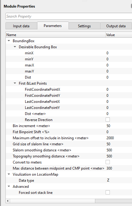
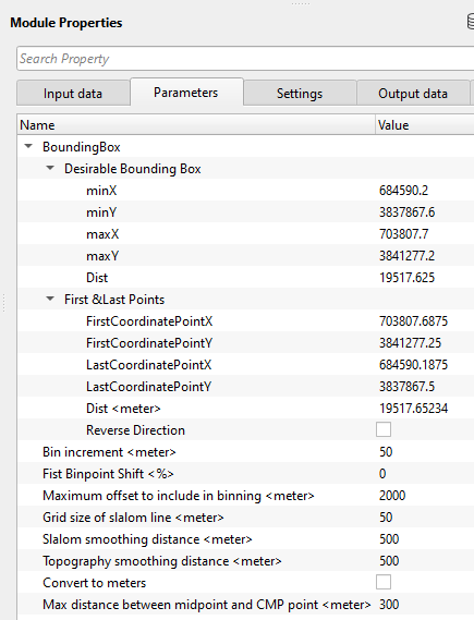
BoundingBox - This section deals with boundary limits of the sail line.
Desirable Bounding Box
minX - Minimum value of the x-coordinate.
minY - Minimum value of the y-coordinate.
maxX - Maximum x-coordinate value.
maxY - Maximum y-coordinate value.
Dist - Total distance of the slalom line.
First & last points
FirstCoordinatePointX - Provide the first valid x-coordinate point.
FirstCoordinatePointY - Provide the first valid y-coordinate point.
LastCoordinatePointX - Provide the last valid x-coordinate point.
LastCoordinatePointY - Provide the last valid y-coordinate point.
Dist - Total distance of the slalom line.
Reverse direction - By default, FALSE (Unchecked). If checked, it will reverse the direction of the slalom line.
Bin increment - Specify the cmp interval or bin increment value. Distance between (CMP) points of stack line.
Fist Binpoint Shift - specify how much distance should be shifted (if at all needed).
Maximum offset to include in binning - provide the maximum offset should be considered in the binning. Only midpoints that have an absolute offset distance less or equal to the specified value will be used in the binning process.
Grid size of slalom line - Grid size that is used for slalom line building.
Slalom smoothing distance - Smoothing distance over which to smooth the slalom line
Topography smoothing distance - Specify the smoothing distance value to be used to create a smooth topography map. This smoothed topography will be used as a floating datum.
Convert to meters - By default, FALSE (Unchecked). If checked, it will convert the existing measurement system from imperial to metric i.e. from feet to meter etc.
Max distance between midpoint and CMP point - Only midpoints whose distance to the bin center point will be included the bin.
Visulization on LocationMap - This section deals with what kind of data type should be displayed on the location map.
Data type { Z, Picket, Sp, NON } - By default, Z (Depth). The user can change from the drop down menu.
Z - Depth
Picket - Source/receiver pickets
SP - Shot Point
NON - None
Advanced -
This group contains advanced options that control the final processing of the stack line. Normally these settings do not require adjustment, but they can help resolve unusual geometry configurations.
Forced sort stack line — When enabled, the module forces an additional nearest-neighbor sort pass on the final stack line after construction. This ensures the CDP sequence follows a continuous spatial order from the first picket to the last. Enable this option only if you observe discontinuities or jumps in CDP ordering along the stack line in crooked-line surveys with complex acquisition geometry. Default: disabled.
Forced sort stack line - If checked, this option reverses the stack sorting direction
![]()
![]()
Number of threads - One less than total no of nodes/threads to execute a job in multi-thread mode.
Skip - By default, FALSE(Unchecked). This option helps to bypass the module from the workflow.
![]()
![]()
Trace headers output - This generates the final updated traces headers with all the bin information which includes the CMPs, CMP elevation, inline, cross line numbers etc.
Stack line - This updates the stack line headers information
Crooked line (for virtual geometry) - This generates the crooked line headers information.
Trace collection bins count - This provides the information about the total number of bins after the binning.
Stack line bins count - Provides the total number of bins in the stack line.
Imported line bin step - Provides the bin step size from the imported crooked line.
Stack line length - Provides the total stack line length in Km.
Number of input traces - Total number of input traces participated in the binning.
Number of output traces - Total number of output traces after the binning.
Number of missed traces - Total number of traces falling outside the bin grid. This information is used for QC purpose to check that all the output traces after binning are inside the bin grid. If any traces are missing outside the bin grid, change the Max distance from the mid point to CMP parameter.
![]()
![]()
In this example workflow, we are reading Poland 2D field seismic and navigation data followed by Geometry application.
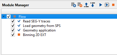
Binning 2D Ext requires input trace headers information. We connect/reference it to Trace headers updated (live only) of Geometry application module.
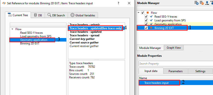
If the user don't know the binning parameters or the bounding box parameters, the user can use the "Build Bounding Box" action item to extract the trace headers information and fill up the default values with the on field data.
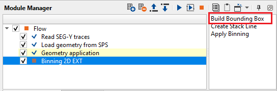
Likewise, the user can use other two action items to perform other tasks.
The output from the Apply binning creates the bounding box along with bin grid, mid points etc.
![]()
![]()
Build Bounding Box - This option let's the user to extract the trace headers information from the input data and automatically fills the bounding box information.
Create Stack Line - This option creates the stack line
Click this action to generate the CMP (common midpoint) stack line from the slalom/crooked line built in step one. The stack line places CDP positions at uniform intervals along the crooked line, using the bin increment you specified. This action must be run after the bounding box has been built. The resulting stack line defines the final CDP numbering and bin positions that will be written to the trace headers when you apply the binning.
Apply Binning - This option allows the user to perform binning which includes, creating the bin mid points, slalom line, crooked line etc.
![]()
![]()
YouTube video lesson, click here to open [VIDEO IN PROCESS...]
![]()
![]()
Yilmaz. O., 1987, Seismic data processing: Society of Exploration Geophysicist
 * * * If you have any questions, please send an e-mail to: support@geomage.com * * *
![]()