Description
The Export CO-MF Results module reads the internal Common-Offset Multi-Focusing (CO-MF) database produced by the Engine modules and exports the stored focusing parameters as seismic gathers in standard g-Platform format (.gsd). Each bin in the database holds the optimal Multi-Focusing parameters for every preserved reflection event — semblance, wavefield curvatures, velocities, and fold — and this module extracts those quantities into individual output gathers so they can be displayed, used for quality control, or fed into subsequent processing steps.
The module supports both 2D and 3D CO-MF databases. Exactly one of the two storage inputs — Storage file 2D-CO or Storage file 3D-CO — must be connected; providing both or neither will generate an error. An optional velocity-corridor picking item can be supplied to constrain which events are selected for the output image, providing consistency with the constraints that were used during the MF search. All selected parameter types are written as separate output gathers whose file names are automatically derived from the Output file name base path.
Use this module after running Engine - 2D CO-MF or Engine - 3D CO-MF to extract parameter volumes from the .kdb database for interpretation, velocity model building, or AVO analysis. The stacked amplitude output is the primary deliverable; the additional parameter gathers (CRE radius, CEE distance, dip, velocities, and fold) provide detailed geophysical attribute information about each reflection event.
Input data
Storage file 2D-CO
Path to the 2D CO-MF database file (.kdb) produced by the Engine - 2D CO-MF module. Connect this input when working with a 2D seismic line. Do not connect both Storage file 2D-CO and Storage file 3D-CO simultaneously — only one may be active for a given run.
Storage file 3D-CO
Path to the 3D CO-MF database file (.kdb) produced by the Engine - 3D CO-MF or Engine - 3D CO-MF Constrain module. When a 3D database is connected, the module reads the bin grid geometry from the database header and automatically populates the DB inline and crossline range fields in the Geometry create confines group. Connect this input when working with a 3D seismic volume.
Picking item
Optional link to a velocity-corridor picking item (G3DPickingItem) that constrains which events are exported. This should be the same corridor that was used to guide the CO-MF search engine. When connected, only events that fall within the defined velocity corridor are included in the stacking and parameter extraction. If not connected, all events stored in the database are used.
Output file name
Base output file path (.gsd). The module generates a separate output gather for each parameter type enabled in the Types group. Each output file is named automatically by appending a suffix that identifies the parameter type (for example, _stack, _correlation, _angle, _cre, and so on) to the base path you specify here. Ensure that the target folder exists and that you have write permission before running.
Parameters
Image creation parameters
This group controls how multiple reflection events stored per bin are combined (stacked) into a single output sample. During the MF Search, up to a user-specified maximum number of directions (events) are preserved for each time sample. Each stored event carries a semblance value, a two-way time, and the full set of MF parameter indices. The image creation step time-corrects all selected events using the optimal MF operator and sums them to form the output image gather. The sub-parameters below control the event selection criteria applied before summation.
During the stacking can be applied different criteria for selection: by angle range, by velocity range or by semblance distribution.
Directions
Maximum number of events to be stack.
Sets the maximum number of reflection events per time sample that will be summed into the output image. The value must not exceed the number of directions preserved during the MF engine run (set in Parametrization - MF engine - Wave values - Maximum number of directions). Default: 1. Using a value greater than 1 can improve signal-to-noise ratio when multiple distinct events are present, but may blur closely spaced reflectors.
•Default: 1
•Values: 1-Maximum Number of Directions preserved during the search
From angle
First value of angle range to stack.
The lower bound of the dip-angle range (in degrees) used to filter events before stacking. Only events whose MF dip angle falls within the [From angle, To angle] window are included. This allows you to restrict the output to events arriving from a particular structural direction. Default: -90°. For a flat-layer stack, keep the default full range of -90° to 90°.
•Default: -90
•Range: -90 - 0
To angle
Last value of angle range to stack.
The upper bound of the dip-angle range (in degrees) used to filter events before stacking. Use this together with From angle to isolate events from a specific structural dip range. Default: 90°. Narrowing this range (for example, -10° to 10°) restricts the stack to near-horizontal reflectors and can improve the image quality in structurally simple areas.
•Default: 90
•Range: 0 - 90
SN Enhance
Turn ON/OFF normalization of data over semblance prior stacking.
When enabled, each event contribution is weighted by its semblance value before being added to the stack. This enhances the signal-to-noise ratio of the output image by giving more weight to events with higher coherence and suppressing contributions from low-confidence events. Default: false (equal-weight summation). Enable this option when the data has variable coherence and you want to automatically downweight noisy events.
Default: False
Correlation threshold
Threshold for event participation in the summation as a percentage ratio of the maximum value.
Events with a semblance value below this threshold (expressed as a percentage of the maximum semblance at that time sample) are excluded from the stack. Set this value higher to be more selective and accept only the most coherent events; set it lower to include more events in the output at the cost of potentially adding noise. Default: 10% (value 10 in the interface, internally stored as 0.1). Valid range: 10 to 90.
•Default: 10
•Range: 10 - 90
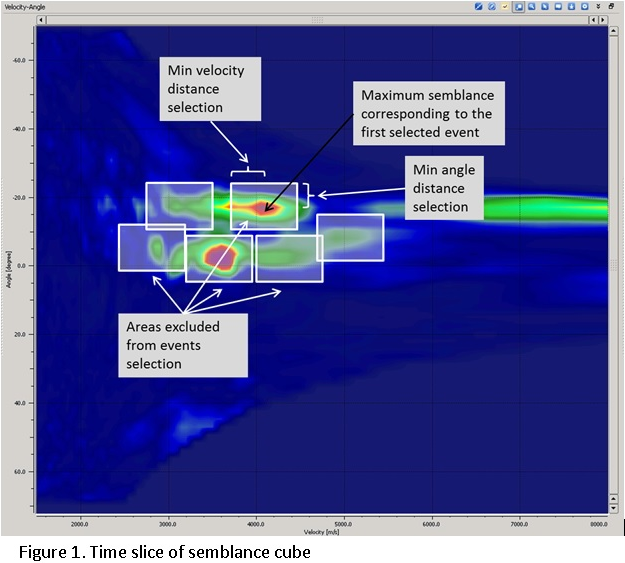
Min angle distance selection
Minimum distance in terms of semblance grid along angle axe, between events selected for summation. Parameter gives possibility to separate events with different correlation by angle (Figure 1).
Controls the minimum separation (in semblance grid index units along the dip-angle axis) between two events that are both allowed to contribute to the stack. This prevents nearby duplicate events from being double-counted when the semblance maximum has been detected at slightly different dip angles. Increase this value to enforce a larger angular separation between selected events and reduce redundancy. Default: 1. Valid range: 1 to 100.
•Default: 1
•Range: 1 - 100
Min radius distance selection
Minimum distance in terms of semblance grid along velocity axe, between events selected for summation. Parameter gives possibility to separate events with different correlation by velocity (Figure 1).
Controls the minimum separation (in semblance grid index units along the velocity/radius axis) between two events that are both allowed to contribute to the stack. This prevents events with very similar velocities but slightly different MF radius parameters from being counted twice. Increase this value to enforce a larger velocity separation between selected events when the semblance panel contains multiple closely spaced peaks. Default: 100. Valid range: 1 to 100.
Default: 100
Range: 1 - 100
Write mode
Controls how the output .gsd files are written. Direct (default) overwrites any existing output files from scratch. Append adds the newly computed bins to an existing output file, which is useful for splitting a large 3D volume export into multiple runs or for incrementally updating a partial result. Use Append only when you are certain the existing output file was produced with the same parameters and database.
Zero padded
When enabled, bins that contain no computed events in the database are written as zero-filled traces in the output gather rather than being skipped. This ensures that the output gather has a complete and regular geometry that matches the acquisition grid, which can be required by downstream modules that expect a regularly sampled volume. Default: false. Enable this option when the subsequent workflow requires a full, gap-free output volume.
Create Params
This group contains parameters that control an optional datum-correction shift applied to all output traces before they are written. Enabling the shift corrects for variations in surface elevation and brings the data to a common flat datum, which simplifies subsequent interpretation.
ShiftToDatum
When enabled, each output trace is time-shifted so that travel times are referenced to the flat datum level specified by the Datum parameter below. This is equivalent to applying a surface-consistent static correction to the exported MF image. Default: false. Enable this option when the acquisition surface is irregular and you need to reference the exported data to a flat datum for interpretation.
Turn ON/OFF shift to final (flat) datum.
Default: false
Datum
The elevation (in metres) of the flat reference datum to which all output traces are shifted when ShiftToDatum is enabled. Set this value to the desired processing datum elevation (for example, the mean surface elevation or the regional datum used in the project). Default: 0 m. This parameter has no effect when ShiftToDatum is disabled.
Value of final (flat) datum.
Default: 0
Geometry create confines
This group defines the inline and crossline range of bins that will be exported. It contains two sets of limits: the DB range (read-only, automatically populated from the database header when a 3D storage file is connected) and the Create range (editable, defining the subset of bins to actually compute and write). For 2D data, only the Create range is relevant. Setting Create range values to -1 means no limit is applied in that direction.
DB minimum crossline
The minimum crossline number present in the connected 3D CO-MF database. This field is read-only and is automatically populated by the module when a 3D storage file is connected. It reflects the actual extent of the data in the database and is provided for reference when setting the Create crossline range.
DB maximum crossline
The maximum crossline number present in the connected 3D CO-MF database. Automatically populated from the database header when a 3D storage file is connected. Use this value as the upper bound reference when defining the Create crossline range for the export.
DB minimum inline
The minimum inline number present in the connected 3D CO-MF database. Read-only; automatically populated from the database header when a 3D storage file is connected. Provides the lower bound reference for the actual inline extent of the database.
DB maximum inline
The maximum inline number present in the connected 3D CO-MF database. Read-only; automatically populated from the database header when a 3D storage file is connected. Provides the upper bound reference for the actual inline extent of the database.
Create minimum crossline
The minimum crossline number to include in the export. Set this to a value within the DB crossline range to start the export from a specific crossline. Default: -1, which means no lower crossline limit is applied and the export starts from the first crossline in the database. Use this parameter together with Create maximum crossline to export a spatial subset of the volume.
Create maximum crossline
The maximum crossline number to include in the export. Default: -1, which means no upper crossline limit is applied and the export continues to the last crossline in the database. Set this to a specific crossline number to restrict the export to a spatial subset of the 3D volume.
Create minimum inline
The minimum inline number to include in the export. Default: -1, which means no lower inline limit is applied and the export starts from the first inline in the database. Use this parameter together with Create maximum inline to restrict the export to a specific inline range within the 3D volume.
Create maximum inline
The maximum inline number to include in the export. Default: -1, which means no upper inline limit is applied and the export continues to the last inline in the database. Set this to a specific inline number to restrict the export to a spatial subset of the 3D volume.
Save Params
This group contains options that control the format and unit system of the exported parameter values in the output gathers.
No Zero Values For Velocity
When enabled (default), samples in the velocity-related output gathers (V Slow, V Fast, and their dip-corrected variants) that have no valid event assigned are left blank rather than being filled with zero. This prevents zero-velocity samples from corrupting velocity model building or interpretation workflows that use the exported gathers. Default: true. Disable this option only if downstream software requires a complete zero-padded gather for all samples.
Convert To Feet
When enabled, all distance and velocity values in the output parameter gathers are converted from metres to feet before writing. Enable this option only if the downstream software or project convention requires imperial units. Default: false (output in SI units — metres and m/s).
Types
This group contains a set of boolean toggles that select which CO-MF parameter types are extracted and written to output files. Each enabled type produces a separate output .gsd gather file whose name is automatically derived from the Output file name base path. Enable only the parameters you need to avoid unnecessary disk usage and processing time. All parameters default to false except Stack.
Stack
Exports the MF-stacked seismic amplitude gather — the primary output of the CO-MF imaging workflow. Each bin contains the coherency-weighted sum of all selected reflection events corrected to their optimal Multi-Focusing surface. This is the main seismic image result and is the output most commonly used for interpretation and further processing. Default: true (always export the stack).
Correlation
Exports the semblance (coherency) attribute gather. Each sample value represents the maximum semblance achieved at that time for the selected events. The semblance gather is useful for quality control of the MF search results and for identifying areas of poor focusing. Default: false.
Angle
Exports the dip-angle attribute gather containing the optimal reflection dip angle (in degrees) at each time sample. This parameter describes the structural dip of the best-focusing reflector at each point and can be used for dip-steering, structure mapping, or as input to dip-filtered stacking. Default: false.
Gamma
Exports the Gamma parameter gather. In the Multi-Focusing framework, Gamma is the angle that parametrizes the wavefront curvature of the hypothetical common-offset wavefield and is related to the reflector dip in the CO-MF operator. This parameter is an advanced attribute used primarily for research, AVO analysis, or as input to further MF-based processing. Default: false.
CRE
Exports the CRE (Common Reflection Element) radius parameter gather. In the Multi-Focusing method, CRE is the radius of curvature of the hypothetical exploding-reflector wavefront at the measurement surface. It is a fundamental MF parameter that describes the subsurface reflector shape and is used to compute the NMO-like correction applied to each trace during stack formation. Default: false.
CRE2
Exports the second CRE parameter gather. This is the second independent CRE radius component used in the 3D Multi-Focusing operator to describe the full three-dimensional wavefront curvature. Relevant only for 3D CO-MF databases. Default: false.
CRE Azimuth
Exports the CRE azimuth attribute gather, which contains the azimuthal orientation (in degrees) of the CRE wavefront curvature principal axis. This attribute describes the in-plane direction of the reflector curvature and is primarily relevant for 3D surveys and anisotropy studies. Default: false.
CEE
Exports the CEE (Common Evolution Element) distance parameter gather. CEE is the second fundamental Multi-Focusing parameter, representing the radius of curvature of the hypothetical normal-incidence wavefront. Together with CRE, it fully parametrizes the MF operator and can be used to derive near-surface velocity information and reflector depth estimates. Default: false.
CEE2
Exports the second CEE parameter gather, which is the second independent CEE radius component required to describe three-dimensional wavefront curvature in 3D surveys. Relevant only for 3D CO-MF databases. Default: false.
CEE Azimuth
Exports the CEE azimuth attribute gather, which contains the azimuthal orientation (in degrees) of the CEE wavefront curvature principal axis. Like CRE Azimuth, this attribute is relevant for 3D surveys and provides directional information about the normal-incidence wavefront curvature. Default: false.
V Slow
Exports the slow velocity (minimum apparent velocity) parameter gather derived from the CO-MF parameters. V Slow corresponds to the smaller of the two principal apparent velocities on the measurement surface and is related to the NMO velocity of the reflector in the inline or crossline direction. This attribute can be used for velocity model building and AVO analysis. Default: false.
V Fast
Exports the fast velocity (maximum apparent velocity) parameter gather derived from the CO-MF parameters. V Fast corresponds to the larger of the two principal apparent velocities and characterizes the reflector curvature in the perpendicular direction. Together with V Slow, it provides a full description of the apparent velocity ellipse at the measurement surface. Default: false.
Dip
Exports the reflector dip magnitude attribute gather. Each sample contains the total structural dip angle (in degrees) of the best-focusing reflector, computed from the optimal CO-MF angle parameter. This attribute is equivalent to the Angle output but may be expressed differently depending on the MF parametrization convention. Default: false.
Azimuth Dip
Exports the dip azimuth attribute gather, which contains the azimuthal direction (in degrees from north or from the survey reference) of the maximum structural dip at each time sample. Combined with the Dip attribute, this provides a complete three-dimensional description of reflector orientation and is useful for structural geology interpretation and dip-steering workflows. Default: false.
VSlow / cos(Dip)
Exports the dip-corrected slow velocity gather, computed as V Slow divided by cos(Dip). This correction removes the geometric component of the apparent velocity reduction that results from structural dip, yielding a velocity estimate that is more directly comparable to the true sub-surface velocity. This attribute is particularly useful for velocity model building in dipping-layer geology. Default: false.
VFast / cos(Dip)
Exports the dip-corrected fast velocity gather, computed as V Fast divided by cos(Dip). Analogous to VSlow / cos(Dip), this attribute removes the dip-induced bias from the fast apparent velocity to produce a dip-independent velocity estimate. Use this attribute together with VSlow / cos(Dip) for building anisotropic or dip-corrected velocity models. Default: false.
Fold
Exports the fold attribute gather, which records the number of raw input traces that contributed to the MF stack at each time sample in each bin. The fold gather is useful for quality control — low fold values indicate areas of sparse coverage where the stack image may be less reliable. This attribute can also be used to apply fold-based weighting or muting in subsequent processing steps. Default: false.