Description
Data Enhance - 3D ZO-MF improves the signal-to-noise ratio of 3D pre-stack seismic data using the Zero-Offset MultiFocusing (ZO-MF) approximation. For each output trace location, the module reads ZO-MF kinematic parameters from a pre-computed database, selects neighbouring raw input traces within a user-defined spatial aperture, applies the MF time-correction to each contributing trace, and sums them coherently to produce an enhanced output trace. Because the MultiFocusing operator does not require CMP symmetry, the output geometry can differ from the input geometry, making this module equally suitable for signal enhancement and for data regularization or interpolation onto a synthetic acquisition grid.
The module requires that the ZO-MF engine (Engine - 3D ZO-MF) has already been run and the resulting .kdb database is available. Processing supports multi-threading and GPU acceleration for large 3D surveys. The enhanced data are written directly to a .gsd output file.
Input data
Output file name
Path to the output .gsd file where the enhanced pre-stack seismic data will be written. This file must be specified before execution. The output geometry is governed by the Output sorted headers and Output BinGrid inputs.
Storage file 3D
Path to the 3D ZO-MF database file (.kdb) produced by the Engine - 3D ZO-MF module. This database contains the MultiFocusing kinematic parameters (wavefront curvatures, emergence angles, etc.) for every imaging point in the survey. The module queries this database to retrieve the MF parameters needed to compute the time correction for each contributing input trace.
SEG-Y data handle
Connection to the SEG-Y data handle item that provides random-access reading of the input pre-stack seismic data. This connector links the enhancement module to the raw field data or any previously processed pre-stack dataset.
Input sorted headers(of seismic data)
Sorted trace headers describing the geometry of the input pre-stack seismic data. These headers define how the raw traces are spatially organized (inline, crossline, offset, source, and receiver coordinates) so that the module can find neighbouring traces for each output location.
Output sorted headers(of synthetic acquisition)
Sorted trace headers describing the desired geometry of the enhanced output dataset. When this geometry differs from the input, the module acts as a data regularizer, synthesizing traces at locations that may not have been sampled during acquisition. The output can represent a regular 3D grid regardless of the irregularity of the input acquisition.
Input BinGrid
The bin grid definition (inline/crossline numbering, bin dimensions, and survey orientation) associated with the input pre-stack data. This is used to spatially locate raw input traces and to compute CMP distances during trace selection.
Output BinGrid
The bin grid definition for the output enhanced dataset. This may be the same as the input grid (for enhancement in place) or a different, regular grid (for regularization onto a synthetic acquisition geometry).
G3DPickingItem
Optional velocity picking item that constrains the enhancement. When connected, the picking corridor is used to limit which MF parameter sets contribute to each output trace, improving the focus of the partial stack around known reflectors. If not connected, no velocity constraint is applied and all MF parameters within the spatial aperture are used.
V0 Map
Optional 2D map of near-surface velocity V0 (m/s) defined on the survey grid. When provided, the module uses spatially varying V0 values to compute more accurate MF time corrections in areas with significant near-surface velocity changes. If not connected, the V0 value stored in the MF database is used uniformly across the survey.
Parameters
Create NMO corrected gathers
When enabled, the output pre-stack gathers are NMO-corrected using the MultiFocusing kinematic parameters, so that reflections are flattened across offsets. Default: disabled. Enable this option when the downstream workflow requires NMO-corrected gathers (for example, before AVO analysis or offset stacking).
MF emulation mute
When enabled, the module applies a mute that mimics the mute function used during the MF engine computation. This ensures that the enhancement does not stack energy from time-offset regions that were excluded during MF parameter estimation. Default: disabled. Enable when the MF database was computed with a mute function and you want the enhanced output to honour those mute boundaries.
Image creation parameters
This group of parameters controls how the MultiFocusing partial-stack image is constructed from multiple directions of wavefront illumination. The key sub-parameters are:
Directions — number of azimuthal directions used during image formation. Default: 1. Increasing this value improves the handling of azimuthally anisotropic data but increases computation time.
From angle / To angle — azimuthal range (degrees) over which directions are computed. Defaults: -90° to +90°.
S/N enhancement — when enabled, an additional signal-to-noise enhancement step is applied during image formation by weighting contributions based on their coherence.
Correlation threshold — minimum coherence (as a percentage) required for a contribution to be included in the partial stack. Default: 10%. Raising this threshold rejects low-coherence contributions and can improve output quality in noisy data, but may also reduce fold in low-signal areas.
Angle distance selection / Radial distance selection — angular and radial binning parameters used when distributing contributing traces across image directions. Defaults: 1 and 100, respectively.
Mute type
Selects how the MF mute boundary is applied to each contributing trace during partial stacking. Default: Use mute factor.
Use mute factor — a single constant mute factor value (set via the Mute factor parameter below) is applied uniformly to all contributing traces.
Use mute function — the time-variant mute function stored in the MF database (applied during MF engine computation) is retrieved and used identically here, ensuring full consistency between the engine and the enhancement steps.
Mute factor
The constant MF mute factor applied when Mute type is set to Use mute factor. The value controls the maximum allowed time shift (in milliseconds) for a contributing trace before it is muted. Default: 1000 ms. Minimum: 0. Reduce this value to mute far-offset traces with large time corrections that may degrade coherency in the partial stack.
CO aperture mode
Defines the geometry used to select contributing raw traces for the partial stack. Default: XY aperture.
XY aperture — traces are selected based on the spatial distance of their CMP location from the output trace CMP, using the Max distance to CMP threshold. This is the standard mode for most 3D surveys.
Offset aperture — traces are selected based on their source-receiver offset range rather than CMP proximity. Use this mode when trace selection should be governed by the offset distribution rather than the spatial footprint.
Kill empty traces
When enabled, output traces that contain no valid data (zero fold, no contributing traces within the aperture) are removed from the output dataset rather than being written as zero traces. Default: disabled. Enable this option to reduce the output file size when large parts of the output grid fall outside the acquisition footprint.
Interpolation properties
This group controls the spatial interpolation method used to estimate MF parameters at output trace locations that do not coincide with stored MF imaging points. The sub-parameters are described below.
Interpolation method
Spatial interpolation method for MF kinematic parameters at output trace positions. Default: Triangulation.
Triangulation — uses Delaunay triangulation to linearly interpolate parameters from the three nearest MF imaging points. Fast and well-suited to regularly sampled MF grids.
Kriging — uses geostatistical Kriging to interpolate parameters from multiple surrounding MF imaging points. More robust than triangulation when the MF grid is irregular or has gaps, but slower. When Kriging is selected, the Covariance type, Kriging range, and Number of points parameters below become active.
Kriging covariance type
The covariance model used by the Kriging interpolator to describe the spatial correlation of MF parameters. Default: Exponential. Options are Exponential, Spherical, and Gaussian. The choice rarely has a large impact in practice; Exponential is recommended for most surveys. Only active when Interpolation method is set to Kriging.
Kriging range
The spatial correlation range (m) used by the Kriging covariance model. Beyond this distance the covariance between two MF imaging points is effectively zero. Default: 100,000 m. For typical 3D surveys this large default ensures that distant MF points still contribute; reduce it if the MF parameters vary rapidly across the survey area. Only active when Interpolation method is set to Kriging.
Kriging number of points
The maximum number of neighbouring MF imaging points used in each Kriging estimate. Default: 15. Increasing this value improves the stability of the interpolation at the cost of additional computation. Only active when Interpolation method is set to Kriging.
Distance for trace selection
Container grouping all aperture and distance parameters that govern trace selection, for both the MF database (MF trace selection sub-group) and the raw seismic data (Raw data sub-group).
MF trace selection
Controls which MF imaging points from the database are used to derive the kinematic parameters for each output trace. The MF imaging point closest to the output trace CMP is found first; only points within the Max distance to MF CMP threshold are then considered.
Max distance to MF CMP
Maximum allowed distance (m) from the output trace CMP to the nearest MF imaging point in the database. Default: 50 m. Valid range: 0–10,000 m. Output traces whose CMP lies farther than this distance from any stored MF imaging point will not be enhanced. Set this value to approximately half the MF engine bin spacing to ensure every output location is covered.
Maximum number of used MF bins
The maximum number of MF imaging points that can contribute their kinematic parameters to a single output trace. Default: 8. Minimum: 1. Using more bins can improve parameter quality in sparse MF grids, but increases processing time. Reduce to 1 to use only the single nearest MF imaging point.
Raw data
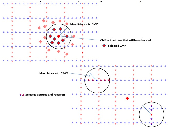
Sub-group controlling selection of raw pre-stack seismic traces that are summed to form each enhanced output trace. Trace selection operates in two stages: first by CMP proximity (Max distance to CMP), then by source-receiver geometry (Max distance to CS-CR).
Spatial decimation factor applied to the input traces before summation, with preservation of the offset-azimuth distribution. Default: 1 (no decimation). Minimum: 1. Set to 2 to use every second trace, 3 for every third trace, and so on. Use this parameter to speed up processing on densely sampled surveys where the full fold is not required for a preview run.
Max distance to CMP
Maximum distance (m) from the output trace CMP to the CMP of any raw input trace that may contribute to the partial stack (first stage of trace selection). Default: 150 m. Valid range: 0–100,000 m. This is the primary spatial aperture parameter: larger values gather more input traces and improve fold, but also increase computation time and risk including energy from structurally different reflectors.
Max distance to CS-CR
Maximum distance (m) from the source and receiver of the output trace to the source and receiver of any candidate input trace (second stage of trace selection). Default: 100,000 m (effectively unlimited). Valid range: 0–100,000 m. Reducing this value restricts the partial stack to traces with source-receiver geometries close to that of the output trace, which can improve coherency in areas with strong azimuthal variations.
Symmetrical aperture
When enabled, the CMP aperture is enforced symmetrically around the output trace CMP: only input traces with their CMP within the radius defined by Max distance to CMP on all sides are accepted. Default: disabled. Enable this option in surveys with regular geometry to ensure a balanced fold distribution around each output location.
Min offset calculation
Minimum source-receiver offset (m) below which input traces are excluded from the partial stack. Default: 100,000 m (effectively no exclusion by default — traces at all offsets are included unless explicitly reduced). Set this parameter to a smaller value (for example 50 m) to skip near-offset traces that may contain surface-wave or direct-arrival energy not corrected by the MF operator.
Use dynamic window
When enabled, the interpolation window used during MF partial stacking starts at zero length and is dynamically extended (up to the Interpolation window length) until the first non-zero amplitude is encountered. This prevents the window from being filled with zeros at the top of the trace where no signal exists. Default: enabled. Disabling this option applies the full fixed window length from the start of each trace.
Interpolation window length
Half-length (s) of the time window used to align and sum contributing traces during the MF partial stack. Default: 0.010 s (10 ms). Valid range: 0–1000 s. This window should be long enough to capture a full wavelet at the dominant frequency of the data. Increase for low-frequency data; decrease for high-frequency data. Larger windows increase computation time.
Stabilization window length
Half-length (s) of the stabilization window applied during the partial stack normalization step. Default: 0.010 s (10 ms). Valid range: 0–1000 s. The stabilization window prevents division by very small values when normalizing the partial stack output. Set this to the same value as the Interpolation window length in most workflows.
Write mode
Controls how the enhanced output traces are written to the output .gsd file. Default: Direct.
Direct — each output trace is written directly and immediately to the output file. Use this mode for a fresh processing run.
Append — new output traces are appended to an existing output file. Use this mode to resume a previously interrupted job or to merge results from multiple processing runs into a single output file.
Max time shift
Maximum allowed MF time correction (s) that can be applied to any contributing input trace during the partial stack. Default: 99,999 s (effectively unlimited). Valid range: 0–100,000 s. Set this to a realistic maximum expected time shift — for example 0.05 s for shallow reflectors — to prevent erroneously large corrections caused by unreliable MF parameters from degrading the output. Contributing traces whose required time shift exceeds this limit are excluded from the partial stack.