Creating a virtual geometry for a 2D marine data
![]()
![]()
Before the actual field deployment of the marine seismic data equipment like the seismic vessel, sources (air guns) and receivers (streamers/cables) a detailed pre-planning survey takes place. This is pretty much mandatory to understand the actual field requirements.
Virtual marine geometry helps in fulfilling the pre-survey planning. With this, the user can design a survey with source and receiver parameters. This will simulate the real world scenario how the source and receivers are placed etc.
![]()
![]()
For this module, there is no input data requirements so the user can ignore this part.
![]()
![]()
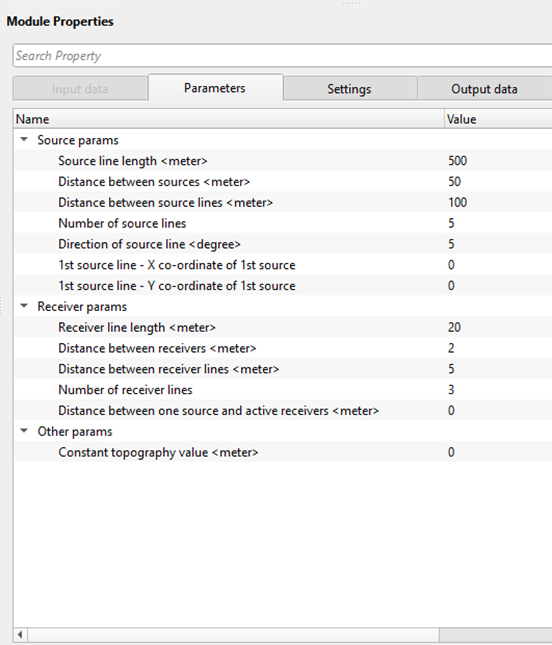
Source params - Design the source parameters
Source line length - This parameter deals with the length of the source line. Specify the total line length in meters.
Distance between sources - This is nothing but a source point interval. Define the SP interval.
Distance between source lines - This is the between source lines. In case of 3D survey, we usually have 2 sources which are alternatively works. So define a distance between two source lines like 100 m, 200 m. In case of a 2D line, you can keep it as zero.
Number of source lines - For 2D it is one and for 3D it should be 2.
Direction of source line - This is the sail line direction.
1st source line - X co-ordinate of 1st source - Provide any virtual x-coordinate value like 100000
1st source line - Y co-ordinate of 1st source - Provide any virtual y-coordinate value like 2500000
Receiver params - This section relates to the receiver parameters
Receiver line length - Provide the cable/streamer length.
Distance between receivers - This is nothing but the receiver point interval. Define the Receiver interval value in meters.
Distance between receiver lines - In case of 3D survey, this is the distance between two adjacent receiver lines. Usually 100 meters is the distance between two receiver lines.
Number of receiver lines - Specify total number of receiver lines. In case of 2D, it will be 1. For 3D survey, it could be 4, 6 etc.
Distance between one source and active receivers - This is the near offset distance between the active source and the 1st active receiver/hydrophone/channel.
Other params
Constant topography value - Zero. For any survey, we've a reference datum i.e. MSL (Mean Sea Level). Since it is a marine seismic survey, the topography/elevation value becomes zero.
![]()
![]()
Skip - By default, FALSE(Unchecked). This option helps to bypass the module from the workflow.
![]()
![]()
Trace headers - We get the out put trace headers with the specified source and receiver parameters.
![]()
![]()
This is a very simple workflow, where we add "Virtual geometry marine (2D)" module inside the Flow and provide various parameters.
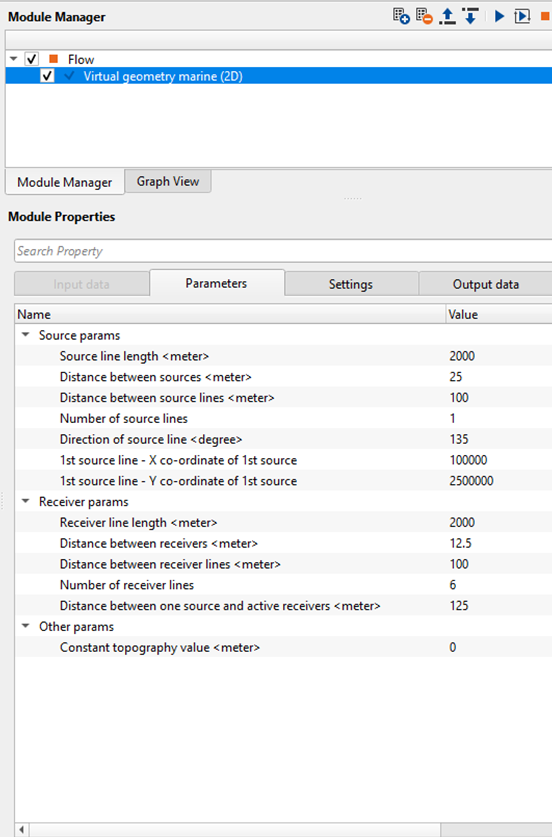
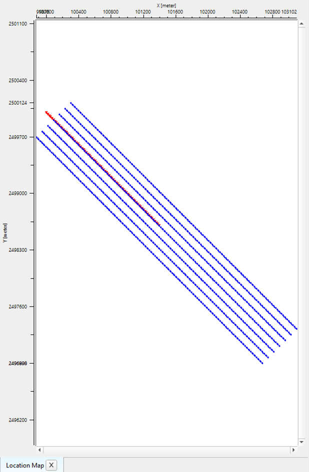
For this module, we get only one vista item i.e. the location map. It will display the source and receivers with the above mentioned parameters. Red lines are Sources and Blue lines are Receivers.
![]()
![]()
There are no action items available for this module so the user can ignore it.
![]()
![]()
YouTube video lesson, click here to open [VIDEO IN PROCESS...]
![]()
![]()
Yilmaz. O., 1987, Seismic data processing: Society of Exploration Geophysicist
 * * * If you have any questions, please send an e-mail to: support@geomage.com * * *