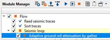
Attenuation of Ground roll in Radon domain
![]()
![]()
Land seismic data contaminated with many types of noise. Out of the most, Ground roll is one the major noise component that predominantly appears on the seismic data.
Ground roll has a distinct characteristics and it is easily identifiable on the seismic records. Ground roll travels along the surface with dispersive velocities. It has low frequency with higher amplitude characteristics. Because of this, primary energy/reflection energy masked by the dominant ground roll noise. Due to the heavy contamination of the ground roll, it is often difficult to interpret the data with it. There are many methods to attenuate the ground roll to improve the signal to noise ratio.
To attenuate the ground roll, we are using adaptive filtering. In this, we analyze the signal and noise components in Radon domain. As we mentioned earlier, ground roll travels in the sub-surface with the dispersive velocities. It has different velocities at the different times. We identify the ground roll based on it's velocity and design the adaptive filter. This filter adjusts dynamically according to the characteristic of the ground roll.
![]()
![]()
Input DataItem
Input gather - Connect/reference to the Output gather. If it is inside the Seismic loop, the previous module output gather will automatically connect/reference to the Input gather of Adaptive ground roll attenuation by gather module.
![]()
![]()
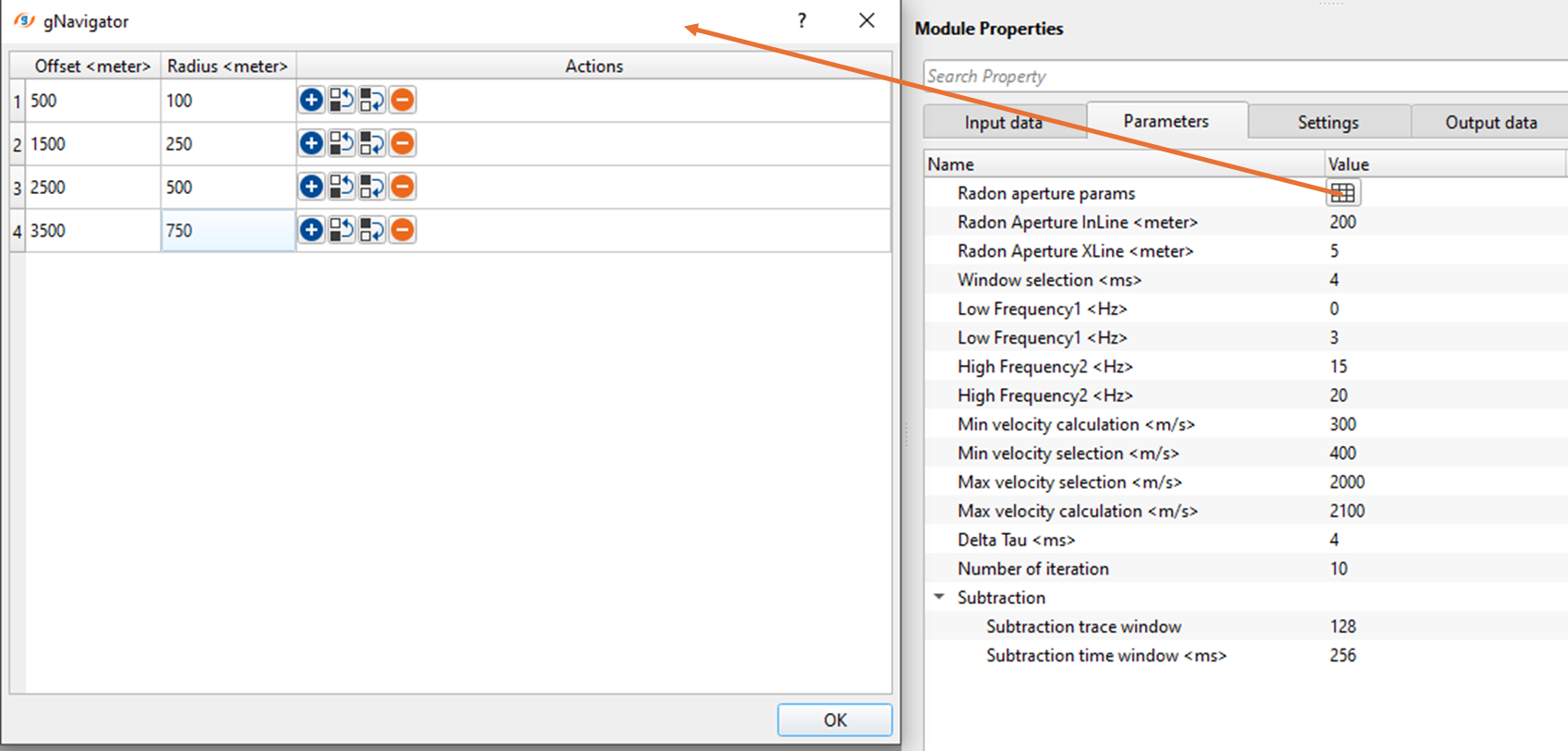
Radon aperture params - This section deals with the radon aperture parameters. Here we've Offset and the corresponding Radius parameter. As we know that the ground roll is in low velocity range between 300 - 800 m/s. Based on these values, it calculates the Pmin & Pmax. For lower velocity values, p values will be higher and for higher velocity values, p value will be lower.
Offset - Offset is used to determine the ground roll's velocity. With longer offsets, ground roll becomes more prominent. In the shallower area, the offset is less and the affect of ground roll is less visible. As the offset increases with time, ground roll also increases. Define the different offsets in the table.
Radius - It is the distance used in the slowness (inverse of the velocity) domain. This parameter is essential for identifying ground roll with specific slowness values.
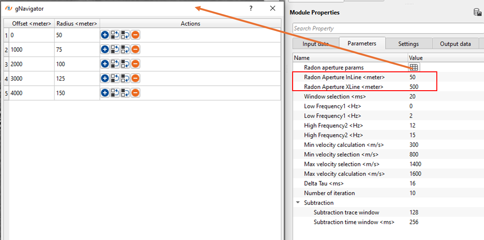
Radon Aperture InLine - no of traces that are considered along the inline (source line) direction to estimate the ground roll characteristics during the radon transformation and design the radon filter. Provide the radon aperture distance along the inline direction. For 2D & 3D, it should be minimum of shot point interval or more. Best starting point should be 25 meters.
Radon Aperture XLine - no of traces that are considered across the crossline (receiver line) direction to estimate the ground roll characteristics during the radon transformation and design the radon filter. Provide the radon aperture distance across the crossline direction. For 2D, this parameter should be less than or equal to the receiver interval. In case of 3D, it should be receiver line distance. The best starting point is, start with 200 meters and upwards as Radon aperture in Crossline direction.
Window selection - to calculate and apply radon filtering within the selected time window.
Low Frequency1 - Specify the lower frequency. Usually starts with 1 and it will be used a taper for Lower frequency 2.
Low Frequency1 - Specify the lower frequency to be consider in ground roll attenuation.
High Frequency2 - Specify the higher frequency to be consider in ground roll attenuation.
High Frequency2 - Specify the higher frequency that works as a taper frequency.
Min velocity calculation - Staring or minimum velocity of the ground roll to be considered. This acts as a taper to avoid any artifacts or edge effects.
Min velocity selection - Specify the minimum velocity to be considered as the ground roll velocity.
Max velocity selection - Specify the maximum velocity of the ground roll.
Max velocity calculation - Provide the maximum velocity that acts as a taper.
Delta Tau - This is the sampling interval in Tau domain. Like the sampling interval in Time domain. This parameter plays a key role in Tau-P. The higher the Delta Tau value, lesser resolution results and the output may not good enough to separate the events in the Tau-P domain however the execution will be faster. On the other side, lower Delta Tau values increases the resolution which eventually gives a better result. The disadvantage of this is higher execution times. Choose the optimum Delta Tau value.
Number of iteration - Specify the number of iterations to be performed
Subtraction - This section deals with the adaptive subtraction.
Subtraction trace window - provide the number of traces to be considered for the adaptive subtraction.
Subtraction time window - provide the time window. Each sample will look for the ground roll characteristics within the user specified time and trace window.
![]()
![]()
Auto-connection - By default, TRUE(Checked).It will automatically connects to the next module. To avoid auto-connect, the user should uncheck this option.
Bad data values option { Fix, Notify, Continue } - This is applicable whenever there is a bad value or NaN (Not a Number) in the data. By default, Notify. While testing, it is good to opt as Notify option. Once we understand the root cause of it, the user can either choose the option Fix or Continue. In this way, the job won't stop/fail during the production.
Notify - It will notify the issue if there are any bad values or NaN. This is halt the workflow execution.
Fix - It will fix the bad values and continue executing the workflow.
Continue - This option will continue the execution of the workflow however if there are any bad values or NaN, it won't fix it.
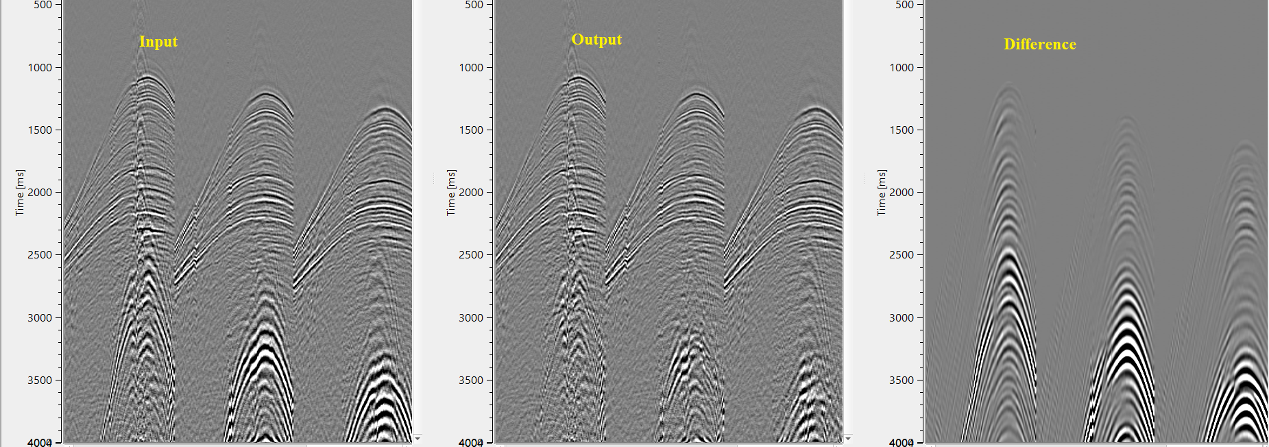
Calculate difference - This option creates the difference display gather between input and output gathers. By default Unchecked. To create a difference, check the option.
Number of threads - One less than total no of nodes/threads to execute a job in multi-thread mode.
Skip - By default, FALSE(Unchecked). This option helps to bypass the module from the workflow.
![]()
![]()
Output DataItem
Output gather - This module outputs the ground roll attenuated gathers.
Gather of difference - Generates the difference between input and output gathers.
There is no information available for this module so the user can ignore it.
![]()
![]()
In this workflow, we've added Adaptive ground roll attenuation by gather module inside the seismic loop. We read the input gather without any denoise procedure applied. Sorted the data in FFID & ABS_OFFSET order.
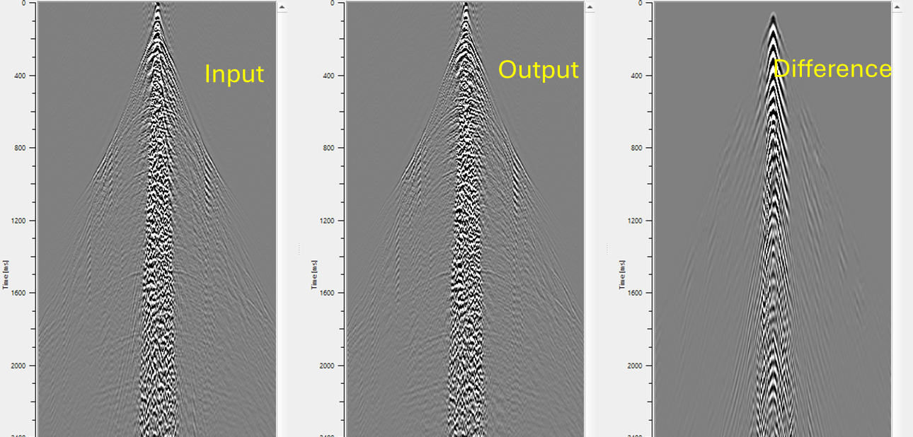
Do enough time on parameter testing. Frequencies and Subtraction parameters plays an important. Test with different higher frequencies and subtraction time window parameters. The parameters shown below are for reference purpose only and NOT FINAL.
The final results of the AGRA by gather are as follows
In case of a 3D dataset,
![]()
![]()
There are no action items available for this module so the user can ignore it.
![]()
![]()
YouTube video lesson, click here to open [VIDEO IN PROCESS...]
![]()
![]()
Yilmaz. O., 1987, Seismic data processing: Society of Exploration Geophysicist
 * * * If you have any questions, please send an e-mail to: support@geomage.com * * *