Description
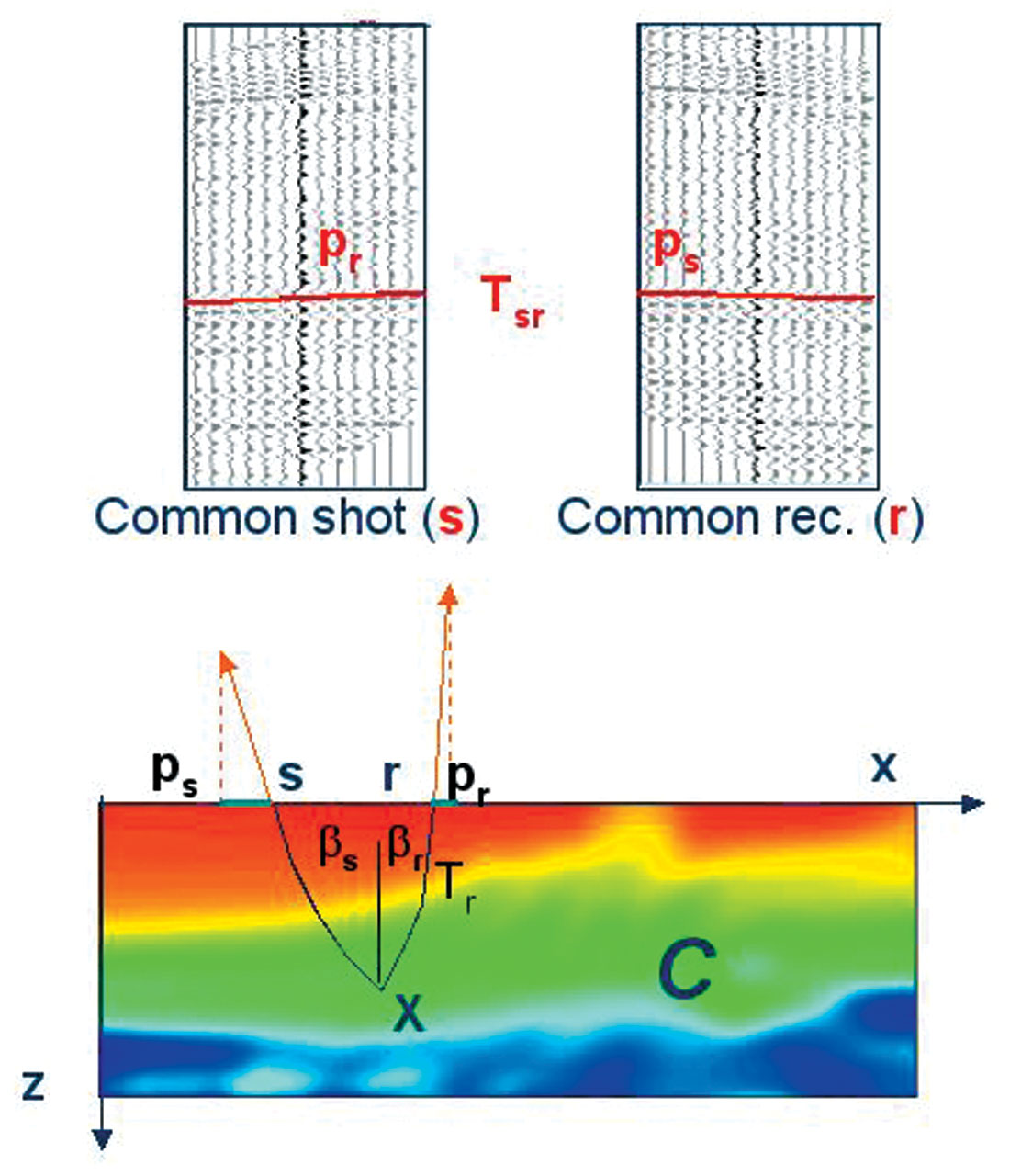
Stereo tomography is based on Ray tracing. The basis of the Stereo Tomography concept is to recognize any locally coherent events characterized by their travel times and local slopes (two slopes) in the prestack data to provide some information about velocity model. (Stereo tomography: Past, present and future - Gilles Lambaré). The locally coherent events can be interpreted as pairs of ray segments and provide the velocity information independently.
How it works?
A stereo tomographic dataset consists of locally coherent events parametrized by source & receiver positions, travel time and slopes of the events in the common shot and receiver domain.
This module is used to generate the updated velocity models. We generate the Tomo items from the PSDM Imaging module. Within the PSDM imaging module, we have "Create tomo parameters" action items and it will create the Tomo item for Stereo Tomography as an input.
Input
Tomo Item full
Fixed constraints horizons - This is optional
Fixed constraints polygons - This is optional
Output
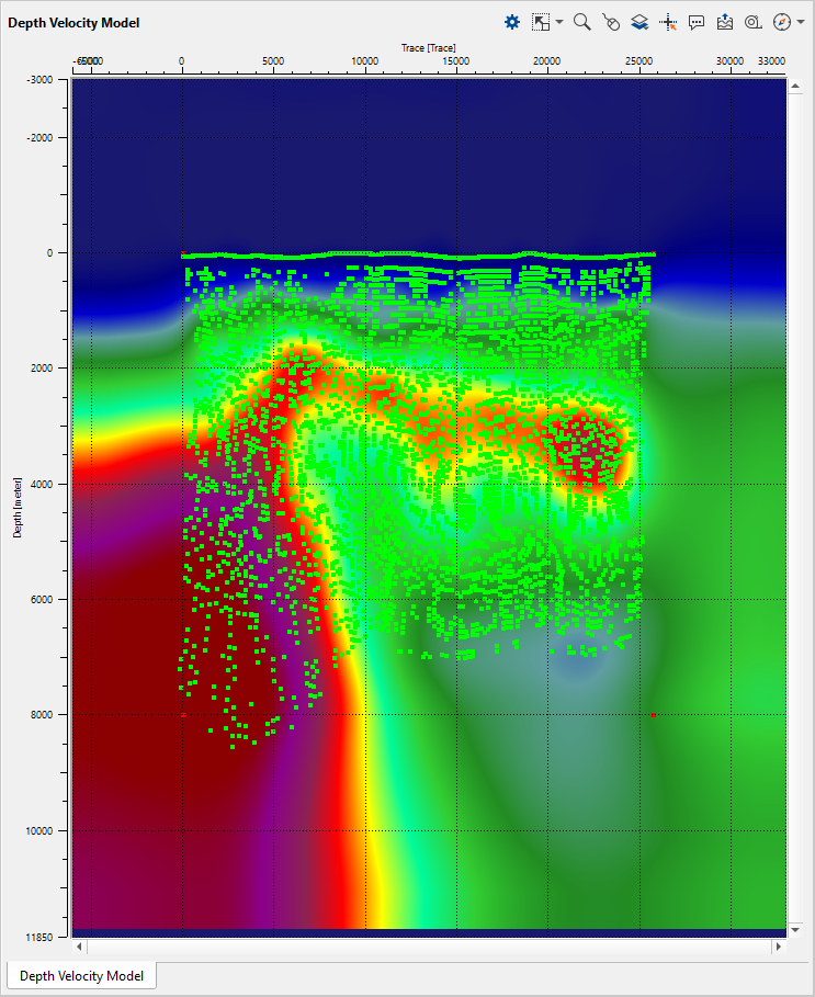
Updated depth velocity model. By using Save seismic by gather module, the user can save the final updated velocity model for next iteration or can be used as a final velocity model.
In the "create tomo params" of PSDM Imaging module, the user should provide the First Step X(meter), Step Y(meter) & Depth (meter). This is important and the size shouldn't be big number otherwise it will thrown error of "Bad allocation" while running the Stereo tomography.
Connect/reference the Tomo item to PSDM Imaging -> Tomo item
Connect/reference Initial velocity or Stack (for Geometry) to Read seismic traces (here the user can read either velocity model or stack for geometry purpose)
Connect/reference Trace headers to Read seismic traces where the velocity/stack is read.
Input data
Tomo item full
Connect/reference the Tomo item full to PSDM Imaging -> Tomo item full
Fixed constraints horizons
In case the user wants to use the horizons as fixed constraints then connect/reference the horizons from the PSDM Imaging module to Output horizons
Fixed constraints polygons
If the user wants to use the polygons, then connect/reference the polygons from PSDM Imaging module to Output polygons.
Parameters
Tomo file name
Use Init Velocity
By default TRUE however if the user check this option as TRUE then the user can ignore the InitialVelocityMin and V0(Velocity) & InitialVelocityMax(Velocity). It is always better to use this option as checked.
Use gather constraints
Layer constraint
Layer from
Here the user can select the layers from the available drop down menu.
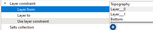
Layer to
Similarly the user can select the layer from the drop down menu for the bottom layer.
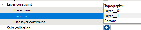
Use layer constraint
If the user wants to use these layers as constraints in stereo tomography then it should be checked.
Salts collection
Datum
Define the datum value.
Velocity from topo to datum(0 - don't fille)
Global iteration count
Define total number of iterations to be carried out. By default 3
Time step
Localization iteration count
Joint inversion iteration count
Define the inversion iteration count. By default 5.
Regularization weight
Outliers threshold
Outliers start
Maximum depth
InitialVelocityMin and V0
Provide the initial velocity value. This will be the starting gradient value
InitialVelocityMax
Provide the maximum velocity value. This will be the maximum gradient value.
InitStepX
This is the initial step in X direction which considers the pickets in the X direction. By default 1200
InitStepY
This is the initial step in Y direction which considers Depth in the Y direction.By default 400.
Adding bound size(samples)
OutputDZ
Calc Alter cost
Sealing Factor
By default 0.5. This value defines the InitStepX & InitStepY values in the subsequent velocity iterations.
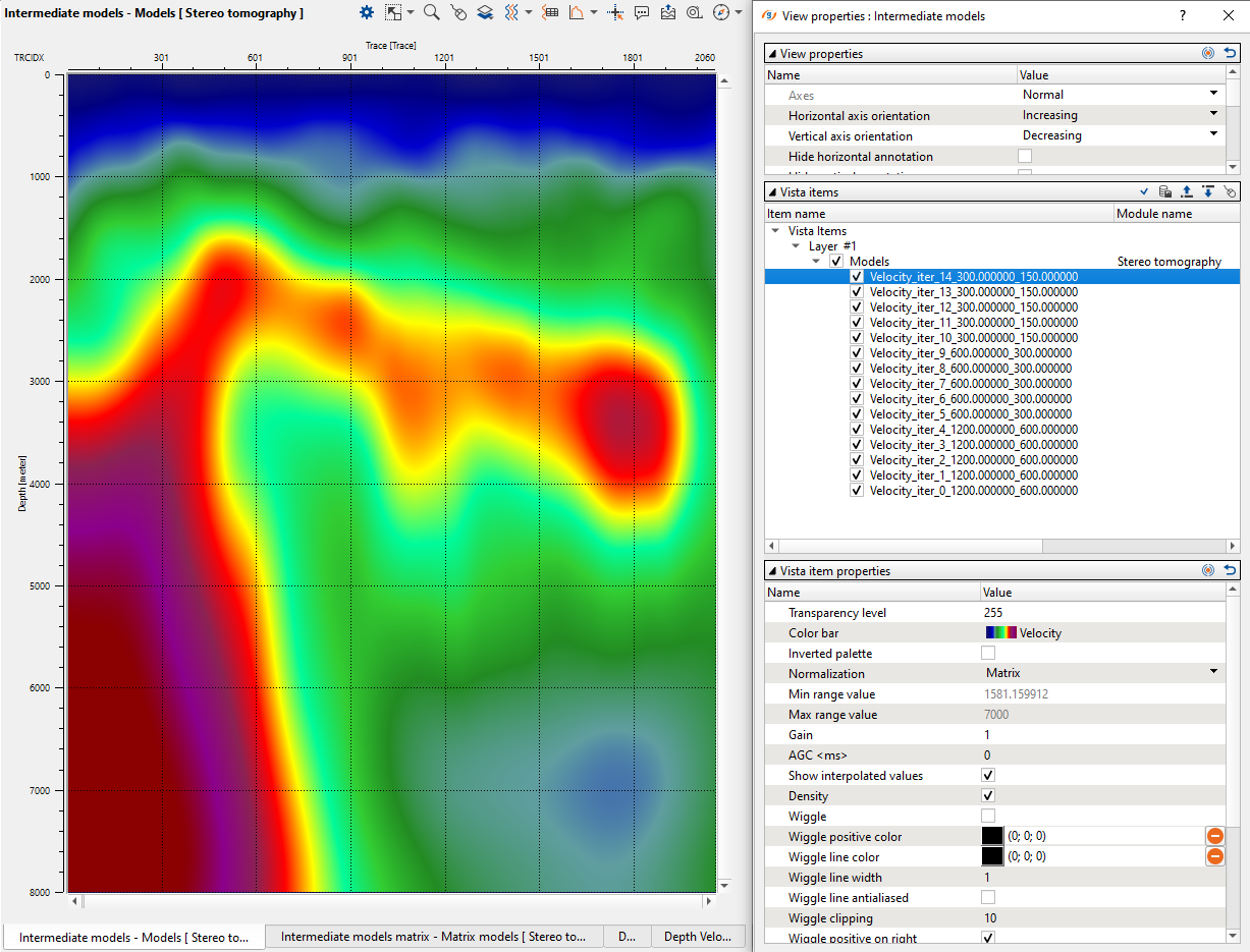
We have 3 global iterations and 5 joint inversion iterations. So in total we'll have 15 iterations. Now these 15 iterations are generated initially with 1200 & 400 as the Initial Step X & Y parameters. So we will have
Iteration1-1200-400
Iteration2-1200-400
Iteration3-1200-400
Iteration4-1200-400
Iteration5-1200-400
Now with the sealing factor of 0.5, Step X 1200 becomes 600 and Step Y 400 becomes 200
Iteration6-600-200
Iteration7-600-200
Iteration10-600-200
Similarly Step X 600 becomes 300 and Step Y 200 becomes 100.
Iteration11-300-100
Iteration15-300-100
Smooth Model Factor
LSQR parameters
Percitnlim
Min vertical shift
Max vertical shift
Create sub models
Path for Depth Models
Provide the path for output depth velocity models
Tomo item read params
Maximum points
Here the user can limit the total number of tomo item points to read. In case there are too many tomo item points and we need to limit then this where the user can limit it.
Max angle
Leave/Remove event
Factor