Description
Surface-consistent residual static correction
Statics – Surface Consistent modules computes the source and receiver residual statics on surface consistent manner.
At the initial stages of the preprocessing, the poor SNR of CMP stack quality is due to the near surface velocity anomalies and topographic changes of the surface. These changes give rise to travel time shifts and it can be corrected by using various methods like refraction statics by means of picking first breaks and calculate the statics and apply them. Second method is Surface Consistent Residual Statics.
In the Surface Consistent Statics, it computes single static solution for all the traces that is coming from the same shot gather. In the case of receiver, separate statics corrections are applied for all the traces from the same receiver. For the combined statics correction, each trace coming from single shot and single receiver will have separate shot static and separate receiver statics. Combining these source and receiver statics give rise to single time shift or static correction.
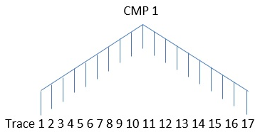
In g-Platform, module Statics – Surface Consistent builds the pilot trace from the CMP stack based on the Model aperture (CMP) defined by the user at the Model & Stack Parametrization. For example if user input the Model aperture (CMP) as 1, it means there will be 3 traces for generating the model trace. There is one trace on the left of the center trace and one on the right side. As a first step, the center trace is cross correlated with the traces on both side of it and generates a model trace and stores in the memory and the process follows to the next trace and so on till to the last trace.
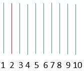
In the above image, red trace acts as center trace and it do the cross correlation with the adjacent traces and generates the model trace. In the second stage of the surface consistent statics calculation, this model trace calculates the shift for the prestack gather of the CMP by means of cross correlating with the each individual trace.
In the final step, we are solving the equations using Gauss Seidel in an iterative way to get the shifts for each individual shot and receiver gathers.
Within this module, we have Velocity Update parameter where in user can enable Velocity updates to automatically update the velocities with each iteration.
Parameters
Model & Stack
Number of CMPs in left and right directions in Cross line
Dip (msec/Tr)
Max CMP shift
Specify the maximum CMP shift value
Super bin aperture(sum near traces)
By default 1.
Use MF model
By default, FALSE. If this is checked, the user should provide the minimum, maximum dip values, Delta dip, Number of directions, Windows selection parameters
Minimum dip
Provide the minimum dip value
Maximum dip
Provide the maximum dip value
Delta dip
Number of directions
Windows selection
Calculation start time
Start time for statics calculation (visualized on stack section)
Calculation end time
End time for statics calculation (visualized on stack section)
Correlation length
The length of cross correlation function.
Maximum value depends on Max shiftparameter: if Correlation length<= Max shift*4, then Correlation length will be equal Max shift*4
Maximum static shift
Maximum static correction
Correlation threshold
Threshold value for correlation from 0-1, if the value will be less than defined, it will not be considered during calculation of statics correction
Number of iterations
Number of iterations of static corrections – cross correlation, solution, apply corrections
Number of Iteratively re-weighted solutions
Number of additional iterations – at each decision stage for the rapid convergence of distributed weight trace
Type
Select the type of calculation from the drop down menu. We have
SC statics shift - by default
SC phase rotation
SC statics shift and phase rotation
Phase rotation step
In case the Type of selection is SC phase rotation then the user should provide the phase rotation step size.
Trend removal
By default, TRUE
Grid size
Smooth
Advanced
CMP term
To stabilize the solution CMP term is used in the equation, but after the solution it excluded and is not used for the formation of effective static correction.
We have three options.
Don't use
Use residual
Use cross correlation - By default
CMP term correction window
If the CMP is used, then the user should provide the CMP term correction window.
Min Fold CMP
Specify the minimum fold CMP i.e. consider the CMP which are having a minimum fold of the user specified value. Any fold value below the user specified CMPs will be part of the statics compute.
Use a residual RMO term
To stabilize the solution residual NMO term is used in the equation, but after the solution it excluded and is not used for the formation of effective static correction
Use RMO limitation
By default TRUE
Use multi-maximum solving
By default FALSE
Use massive cross-correlation aproch
By default FALSE
RMO aperture
Aperture for smoothing the found Residual NMO (it used with “ Whether to use a residual NMO term in the Gauss-Seidel solution” parameter). “0” – will disable the smooth option
RMO minimum offset
Specify the minimum RMO offset.
Performance settings
Parameters for optimization of statics corrections
Max binning fold
Maximum fold. It used for automatic calculation of the size of data blocks that will be loaded into RAM
RAM cash size
Maximum amount of RAM allocated memory for the calculation of statics corrections. It used for automatic calculation of the size of the data blocks that will be loaded to RAM memory
Setup block size manually
Manual definition of the size of the data blocks to load to RAM. This automatically determines the required amount of memory
Block size Inline(CDP)
Block size in Inline direction
Block size Crossline
Block size in Crossline direction
Use cacher
By default, TRUE.
Visualization settings
Create stacks
By default FALSE. Check this feature to create stacks to visualize the stack response for each iteration
Show additional graphics every N iteration
Provide the number to display the stacks after each iteration. For example if user input 15 iterations then wants to see every 5th iteration, user needs to input 3 here.
Stacks for inline #
In case of 3D, the user can specify a particular inline
Stacks crossline #
The user can specify the crossline.
Velocity update
By default FALSE. Check this feature to automatically update the velocities
Create vrms models for iterations
By default FALSE. If checked, it will create the Vrms model
Velocity update each N iteration
By default 1. The user can define the number of velocity update iterations. If the user provides the same number of iterations as the residual statics stack iterations then it will generate the velocity as well stack for each iteration.
Corridor auto picking
Provide the velocity value for automatic picking
Auto picking trace step
Auto picking time step
Velocity increment
Semblance smoothing window
Stretch factor for auto-pick semblance
Normalization window
Smooth type
Select the appropriate velocity smooth type
Smooth window vertical direction
Specify the velocity smooth value (ms) in vertical direction
Smooth grid x direction
Specify velocity smooth (traces) value in X direction
Smooth grid y direction
Specify velocity smooth (samples) value in Y direction
NMO
Input gathers type
Select the appropriate input gather type from the drop down menu
1.NMO Gathers
2.Gathers without NMO
Vrms model
In case the user selected the Input gathers type as “Gathers without NMO” then provide the Vrms model
Stretch factor
Specify the NMO stretch factor
Smoothing parameter Y velocity
Shift to datum
By default FALSE, if checked then the user should provide the datum value in the next parameter
Datum
Provide the datum value
V0
Specify the near surface velocity/replacement velocity
Variable V0 matrix
Use variable V0 (matrix)
Improving static
Try to improve static
Auto pick criteria
Min slope
Max slope
Slope step
Bad traces threshold
Trace half window
Time half window
Use previous result
By default FALSE. If checked, the user should load the previous ".rstat" file.
Save statics iterations path
Provide the path to save the computed statics solutions