Description
Main function for MF Search that determines all parameters of MF
This procedure prepares MF parametrization tables that used by MF Engine procedures. This procedure determines all parameters for all types of implemented MultiFocusing engines
Output data – MF Tables Parametrization
Input data
SEG-Y data handle (for auto Time Range)
Service object provides the ability to read seismic data in specified format. It used for automatic determination of time range in seismic data (optional)
Trace headers (for auto Aperture Offsets)
Table of trace headers. Is used for automatic determination of minimum and maximum offsets (optional)
Parameters
V0
Average velocity in the upper part of the section.
Used for calculation of time correction in MF and transformation R CRE<->V RMS-MF.
Usually is set equal to the Replacement Velocity.
Default: 1500
Dimension Of MFT Process
Dimension of MF search:
•2D
•3D or Wide
•2D Line
Default: 2D
Values: 2D, 3D, wide 2D line
Search Type
Type of MF search:
•Reflection Only – simplest MF Search aimed to stack only reflection events.
•Reflection and Diffraction - search aimed to stack reflection events and enhance diffraction. To each iterated R CREadded additional R CEEequal R CRE.
•Diffraction Only – aimed to stack only diffraction events. Searching only for pairs R CRE=R CEE.
Default: Reflection and Diffraction
Values: Reflection and Diffraction
Diffraction Only
Reflection Only
Use Prestack Mute function
Determination of type and form of MF Mute Function. There are 3 types of MF Mute functions; two of them based on the correlation between the time-offset and R CRE. For the shallow part of the data, the radius of the wave-front approximation cannot be much greater than the offset. For each time determines max offset for stacking using following equation:
OffsetMAX(t)=R CRE(t)*Mute Factor(t);
The difference between the types is in R CREdetermination.
•Firsttype– maximum offset determinate for each iterated CRE,
•Second type – the R CREvalues calculate from the low (left) border of the velocity constrain function for given imaging point location.
•Third type of MF Mute function is based on the limitation of maximum time correction during MF stacking.
Turn ON/OFF in order to switch to the second type MF Mute Function calculation, based on the velocity constrain.
Offset-mute function
Table for time-variant Mute Factor calculation
Default: Time – 1sec
Mute Factor – 3
Mute Factor range: 0.2-4
Mute cee factor
Delta Velocity OffsetMute(-1 not use)
Min-Max Velocity Contour
Time Range
Start
Seismic data start time.
Filled automatically when SEG-Y Data Handle (for auto Time Range)connected, otherwise must be defined by user.
End
Seismic data end time.
Filled automatically when SEG-Y Data Handle (for auto Time Range)connected, otherwise must be defined by user.
Step
Size
Dip Range(Beta)
From
First value of angle range to scan
To
Last value of angle range to scan
Default:±0.8 rad
Range:±1.57 rad
Step
Quantization step during the search
Default:0.01 rad
Range:0.08-0.0001 rad
Size
Number of angles that will be searched, recalculates automatically
Azimuth of Dip Range(Gamma)
From
First value of angle range to scan
To
Last value of angle range to scan
Default:±0.8 rad
Range:±1.57 rad
Step
Quantization step during the search
Default:0.01 rad
Range:0.08-0.0001 rad
Size
Number of angles that will be searched, recalculates automatically
R-cre Range
Reference CRE Offset
Reference offset for CRE table calculation.
Default:3500
Range:usually around max offset of the seismic data
Minimum CRE Radius
Minimum CRE radius matches to low velocity
Default: 5
Maximum CRE Radius
Maximum CRE radius matches to high velocity
Default: 100000
Time Step
Used for CRE radius table construction
Default: 8
Size
Number of CRE radii that will be searched, recalculates automatically
R-cee Range
Parameterization for digitization of CEE radii search table. Table of radii is created as following; the difference between kinematic corrections for two neighbor radii on reference offset shouldn’t exceed the time step.
Reference offset corresponds to the stacking aperture (base of super-gather).
CEE Aperture
Reference offset for CRE table calculation
Default: 300
Range: usually corresponds to the stacking aperture
Minimum CEE
Default:-500
Maximum CEE
Default:500
Time Step
Used for CEE radius table construction
Default:8
Max Number of CEE per CRE
Number of CEE radii that will be searched, recalculates automatically
Velocity Range
Parametrization of velocity, while search performed in radii more useful, ranges to be defined as velocity
From
Minimum velocity for velocity analysis (search)
Default: 1500
To
Maximum velocity for velocity analysis (search)
Default: 8000
Step
Parameter used for visualization of the velocity semblance
Default: 50
Size
Number of velocities for visualization, recalculates automatically
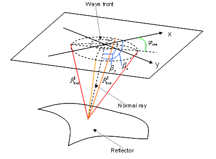
Anisotropy
Anisotropy of the wave-front elements in MF is defined by three parameters R 1 CRE, R 2 CREand ɸ CREwith assumption that reflectors above the target reflector have low curvatures and anisotropy is limited. Parameters R 1 CRE, R 2 CRE, which can be recalculated into V RMSand V INT, are not dependent on dip unlike in CMP where Vst depends on dip.
Azimuthal variation of MF move out velocity is an ellipse in the horizontal plane, irrespective of the type or degree of intrinsic anisotropy. Parameters R 1 CREand R 2 CREare transformed into V 1 RMS==V FASTand V 2 RMS==V SLOW. These additional parameters make possible to take into the account the anisotropy of the subsurface. In the same time this dramatically increase the calculation time.
Anisotropy
Turn on/off the anisotropy search.
•NON – no anisotropy.
•One Azimuth In Line Direction – Anisotropy search performed only along 1 azimuth.
•All Azimuths – search performed for all azimuths.
Default:NON
Values: NON, One Azimuth In Line Direction, All Azimuths
Max CRE Anisotropy
Maximum difference between VFAST and VSLOW to be searched, directly influence on calculation time
Default:0.2
Values:0,6-0.9
Azimuth Factor
Sparsing of number of azimuths that will be searched
1- all azimuths
Default: 1
Values:1-10
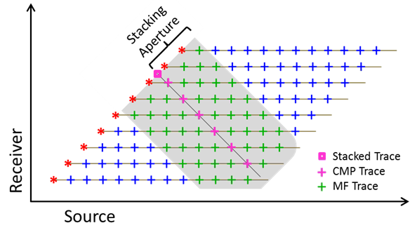
Aperture
Parametrization of super-gather formation.
Super-gather is actually a time projection of the First Fresnel Zone.
All events within this range will be stacked into one sum trace.
Aperture In Inline Direction
Aperture in stack line direction for 2D case and InLine direction for 3D case.
Measured in in the percentages of the First Fresnel Zone.
Default: 50
Range: 10-100
Aperture in perpendicular to stack line direction for 2D case and XLine direction for 3D case.
Measured in in the percentages of the First Fresnel Zone.
Default: 50
Range: 10-100
Azimuth aperture
Maximum offset
Minimum offset
Min Fresnel Zone
Average Frequency
Frequency used to compute size of the First Fresnel Zone.
Default:45
Range:Usually used nominal frequency of the seismic data
Max Reflection Angle
Set Initial azimuth manually
InitialAzimut
Correlation parameters
Parametrization of semblance MF calculation
Correlation Type(Don't change)
Turn ON/OFF third type of MF Mute Function calculation according to limitation of maximum time shift during the MF stacking. It can be used together with first or second type
Max time arrival shift
Value of maximum Time Shift during MF stacking
Selection Window
Min Fold
Minimum MF Fold used for calculation, if fold is smaller than Min Fold the semblance of such sample is set to zero
Default: 5
Range: 5-30, influence the shallowest part of the section
Max Fold
Maximum number of traces considered for stack. Algorithm of sparsing super-gather implemented in order to leave equal number of traces per offset class
Default:99999
Time variant correlation Window
Window used to smooth semblance in time
Default: 14
Range: 5-30
Wave Values
Smooth For Detection Type(Don't change)
Smoothing Cre
Smoothing Angle
Correlation Cre
Window used to smooth semblance along velocity axis
Correlation Angle
Window used to smooth semblance along angle axis
Selection distance Cre
Selection distance Angle
Max number of directions
Number of MF-NMO applied events to be saved in database for each time sample.
Wavelets (events) preserved in database according to the semblance value, starts from the highest.
Default: 10
Range: 5 – 100
Limit number of direction by semblance
v
Cmp fold
Cmp step
Velocities for view
Comments
Angle ranges– usually angle range is a separate test. This is an important parameter in 2D processing that can suppress out “of plane energy” coming with anomalous high angles (parallel to the surface). In 3D processing this parameter directly influence on calculation time.
R CREParameters – In general import the total number of CRE radii that will be searched, for test it might be around100-130 while for “Final Case” might be 200+. This parameter directly influence on calculation time.