![]()
![]()
At the beginning of the marine data acquisition project, the survey team prepares the survey parameters. In that, it will define all the survey related parameters like, Shot Point Interval, Receiver Point Interval, Sail line shooting direction, Near offset, No of Channels, Nominal acquisition fold, No of cables/streamers, near and far offset etc. Also, it includes the no of sail lines with pre-defined sail line directions. These are also known as pre-plots. These pre-plots are prepared with all the real world coordinates. This is a conventional marine acquisition procedure. During the marine data acquisition, the source lines and receiver lines are pre-plotted and try to acquire the data along the predefined sail lines, however marine environment is not stable due to the sea conditions with heavy swell. Because of this, there is a difference of pre and post acquisition sail line positioning.
On the other hand, Nominal marine geometry deals with a set of acquisition parameters used to create a pseudo geometry. This works in the local coordinate system. With the nominal marine geometry application, all the source and receiver positions are at the accurate location as per the parameters defined in the nominal marine geometry module. This module creates unique receiver SP's which is very useful for any common receiver domain applications like noise attenuation, deghosting etc.
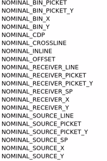
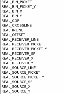
When the data is transferred from original geometry to nominal geometry it creates additional trace headers information with Prefix as NOMINAL & REAL.
![]()
![]()
Input DataItem - Connect/reference to the Output Dataitem of "Read seismic traces"
Input trace headers - Reference to the output trace headers of "Read seismic traces"
![]()
![]()
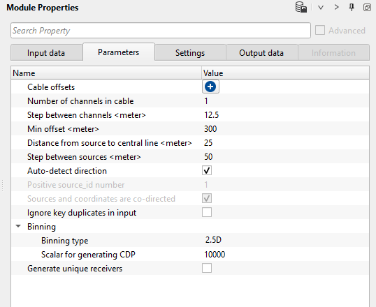
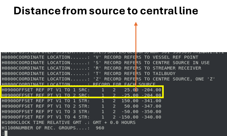
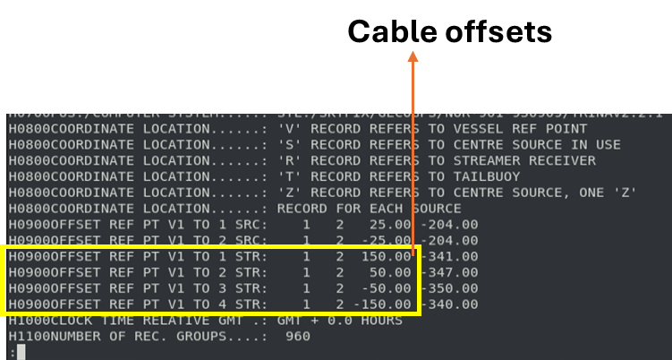
Cable offsets - Define the individual cables/streamers offsets. This information is available within navigation file (P190). For reference, we've provided the images towards the end of the parameters section.
Number of channels in cable - provide the total number of channels existing in a single cable/streamer.
Step between channels - distance between two adjacent channels/hydrophones which is also known as receiver point interval or receiver interval.
Min offset - specify the minimum offset or near offset
Distance from source to central line - this is the distance from the source to the central line
Step between sources - In marine acquisition, if there are dual sources then it will be alternative shooting or flip-flop shooting. If the actual shot point interval is 37.5 m then the adjacent shot point interval will be 18.75 m. All the even shot points will have 37.5 m shot interval so does the odd shot points.
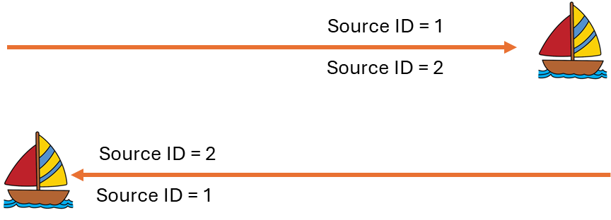
Auto-detect direction - By default, checked (Yes). It will automatically detects the acquisition shooting direction and assigns the correct source ID. If unchecked, then the user should provide the positive source ID and Sources and coordinates are co-directed parameters.
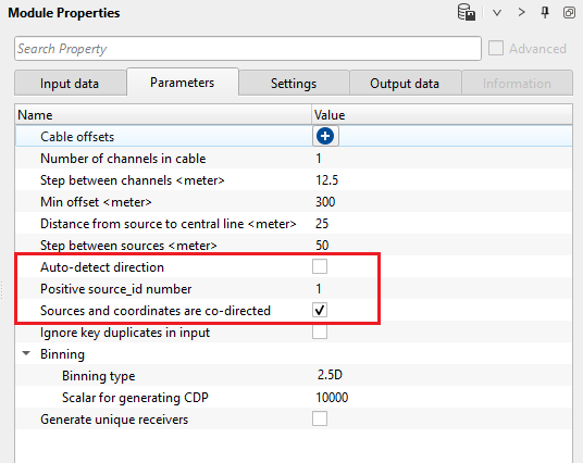
Positive source_id number - By default, 1. If the ship moves along the sail line direction from left to right, the source ID will be 1 (upper side of the sail line) and source ID will be 2 (bottom side of the sail line). In case the ship moves along the sail line direction from right to left, the source ID will be 2 (upper side of the sail line) and 1 (downside of the sail line)
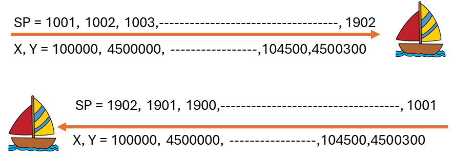
Sources and coordinates are co-directed - It means if the source point numbers are in increasing order along with the increase in coordinates, it will be in the same direction. Whereas, if the source point numbers are in increasing order but the coordinates are in decreasing order they are not in co-directed to each other. By default, it is Checked which means both source and coordinates are in increasing order.
Ignore key duplicates in input - By default Unchecked (No). If it is opted, then it will ignore any duplicate shots in the input data.
Binning - This parameter do the binning within the module to generate the bins information based on the source and receiver information provided in the previous parameters. Inside, we've two kinds of Binning. 2D and 2.5D.
Binning type { 2D, 2.5D } - Select the appropriate binning type to do the partial binning of the sail line inside the nominal marine geometry module. If the sail line is 2D then it will perform a simple 2D binning.
In case the survey is a 3D then the user should select the 2.5D binning type. This will create the bins for each source and receiver combinations. For example, if we've 2 sources and 4 cables/streamers then we'll get 8 cmp lines.
Scalar for generating CDP - specify the scaler value for CDP generations. By default 10000
Generate unique receivers - By default, Unchecked (No). If checked, this will generate unique receiver SP. This is very useful when the user wants to do any kind of noise attenuation or any processing in common receiver domain, we'll get an unique receiver SP numbers which makes it easy to sort the data in common receiver domain.
Scalar for generating receiver SP - specify the scalar value for generating the receiver SP to make them unique.
![]()
![]()
Auto-connection - By default Yes (Checked)
Number of threads - One less than total no of nodes/threads to execute a job in multi-thread mode.
Skip - By default, No (Unchecked). This option helps to bypass the module from the workflow.
![]()
![]()
Output trace headers - This modules outputs the updated trace headers with all the information stored in it's trace headers
![]()
![]()
In this example, we've a workflow with "Read seismic traces" & "Nominal Marine Geometry" modules.
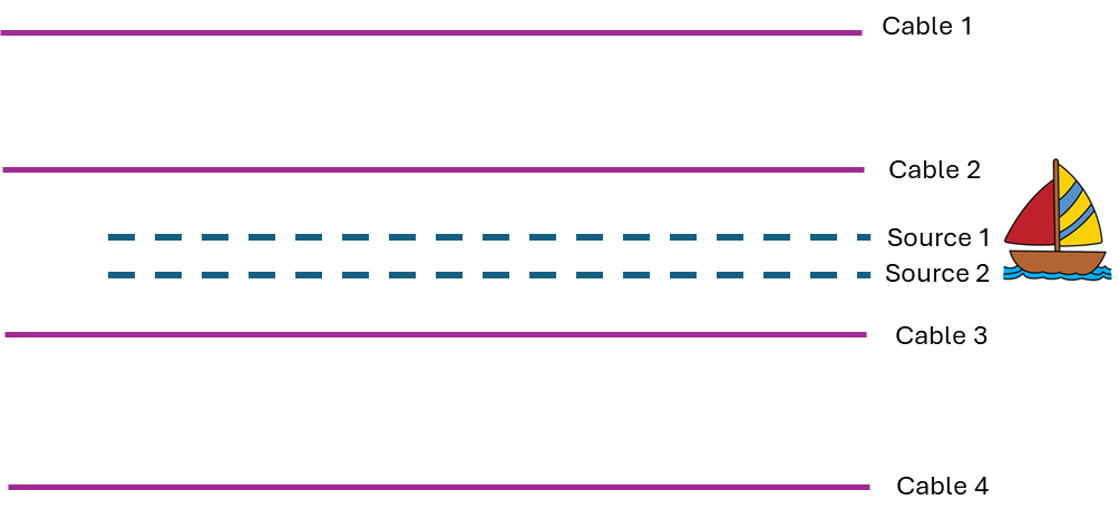
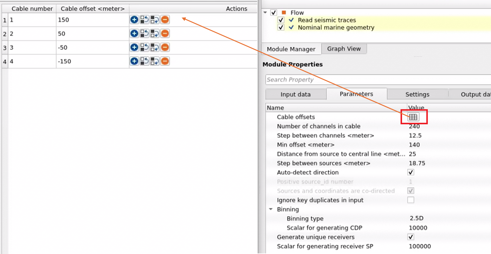
For this particular line, we've 4 cables/streamers of each with 240 channels. Shot point interval is 37.5 m however it is the flip-flop shooting so the distance between adjacent shot point is 18.75 m. Distance between two receivers/channels is 12.5 m and the Minimum offset is 140 m.
We've defined the Cable offsets as 150, 50, -50, -150 m respectively for Cables 1, 2, 3 & 4. This information is available within the navigation file (P190)
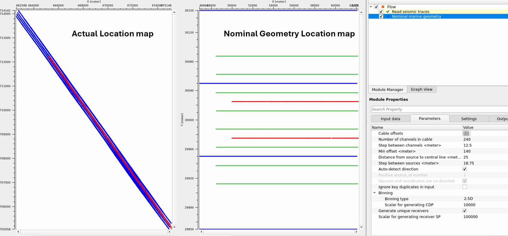
In the above image, we've the actual/field location map and in the middle we've Nominal Marine Geometry Location Map. These vista items were generated with the above parameters after the execution of "Nominal marine geometry" module.
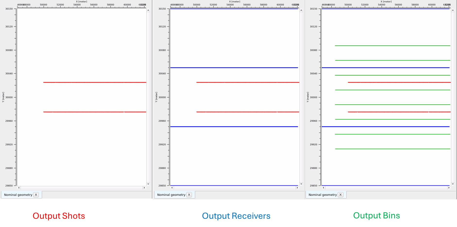
Nominal Geometry location map comprises of Output shots, Output receivers and Output bins.
![]()
![]()
YouTube video lesson, click here to open [VIDEO IN PROCESS...]
![]()
![]()
Yilmaz. O., 1987, Seismic data processing: Society of Exploration Geophysicist
 * * * If you have any questions, please send an e-mail to: support@geomage.com * * *