Polygon picking
Picking polygon
Theory
Polygon picking is an interactive QC and editing technique used in seismic data processing to manually select and isolate groups of traces, events, or noise patterns within a 2D or 3D display. The user draws a closed polygon around an area of interest
It can be used in many ways for identifying bad traces, noise bursts, blending interference, ground roll, or migration artifacts—and the software applies the chosen operation (mute, kill, edit, extract, or analyze) only within that polygon. It provides precise, localized control and is especially useful when automated algorithms cannot reliably differentiate signal from noise.
Input data
There is no input data requirement for this module so, the Input data tab is disabled.
Parameters
Current polygon { Polygon-1 }
it displays the current polygon name.
Smooth parameters
this section deals with polygon smoothing parameters.
Smooth radius
specify the distance over which the polygon boundary will be smoothed. It will avoid any edge effects or sharp boundaries.
Number of smooth points
specify the number of smoothing points that are used for an interpolation of these points for smoothing of the polygon edges. Less number of points, sharp edges.
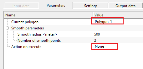
Action on execute { None, Import from text file, Autodetect from trace headers }
this section deals what will happen when the polygon picking module is executed.
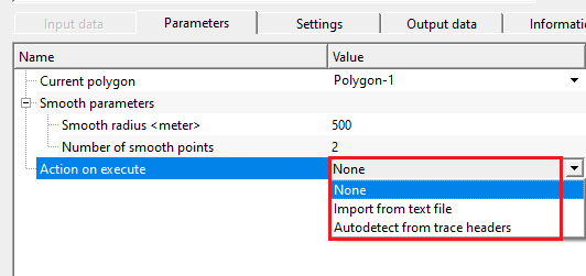
Action on execute - Import from text file
this option allows the user to provide/import the input polygon file in text format.
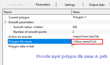
Polygon file name
specify/provide the path of the input polygon file in text/ascii format.
Polygon data in feet
by default, FALSE (Unchecked). If checked, it will identify that the input polygon file data is in feet.
Action on execute - Autodetect from trace headers
this section deals with trace headers. It automatically detects all the information from the trace headers.
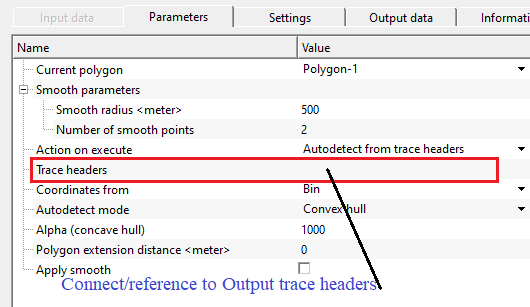
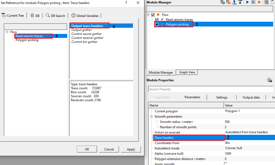
Trace headers
connect/reference to output trace headers to get the trace headers information like coordinates etc.
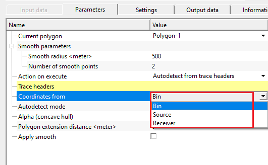
Coordinates from { Bin, Source, Receiver }
select the options from where to get the coordinates from. By default, Bin.
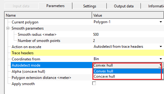
Autodetect mode { Convex hull, Concave hull }
it is the methodology which is used to detect the edges of the polygon. By default, Convex hull.
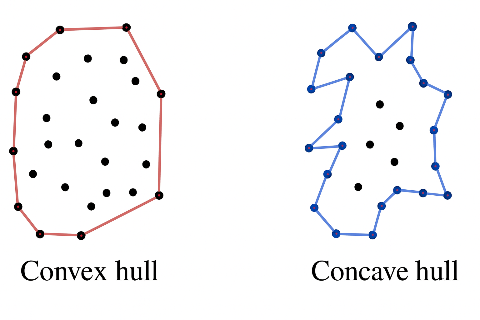
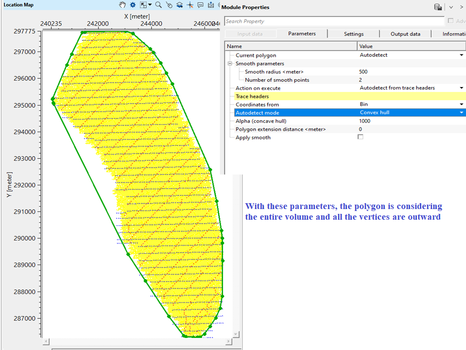
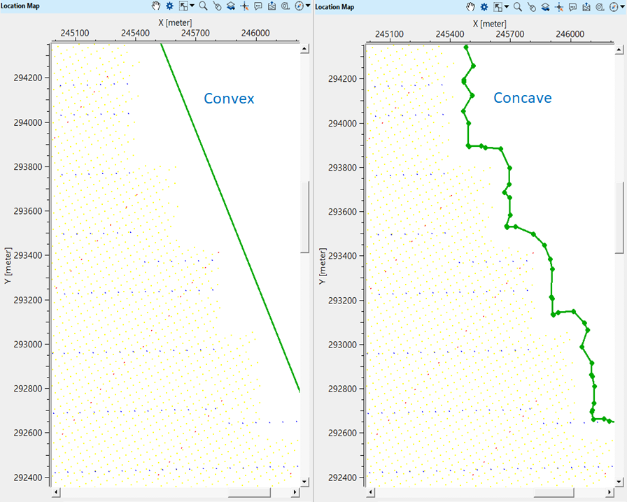
Convex Hull - produces the smallest convex polygon enclosing all detected points, useful for simple and wide muting tasks. In this, all vertices are pointed outwards.
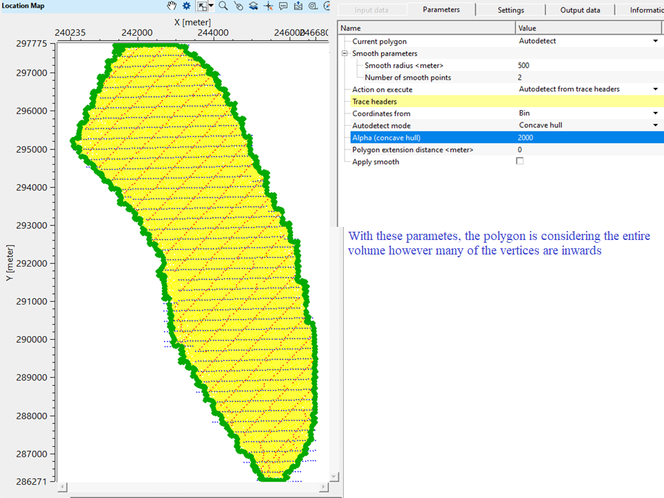
Concave Hull - produces a more accurate, inward-curving polygon that adapts to the true geometry of noisy or anomalous areas, ideal for irregular, localized noise. In this, at least one vertex is inward.
Alpha (concave hull)
the maximum radius of the empty circle used to test whether an edge between two points should be included in the polygon or not. By default, 1000. Low alpha value detects small gaps, holes and inward curves.
Polygon extension distance
specify the maximum distance that can be extended for a polygon
Apply smooth
by default, FALSE (Unchecked). If TRUE (Checked), it will apply smoothing to the polygon to avoid any sharp edges etc.
Settings
Skip
By default, FALSE(Unchecked). This option helps to bypass the module from the workflow.
Output data
Output polygons
generates the output polygon as an output.
Information
Number of vertices
displays the total number of vertices of the current polygon.
Perimeter
displays the total/continuous line distance of the polygon.
Area
displays the total area of the polygon.
Examples
In this example workflow, we are picking a polygon of a 3D seismic data volume. To pick the polygon,
1. Read the seismic volume by using "Read seismic traces" and add Location map vista item by using Vista Groups -> Location map -> In a new window.
2. Add Polygon picking module.
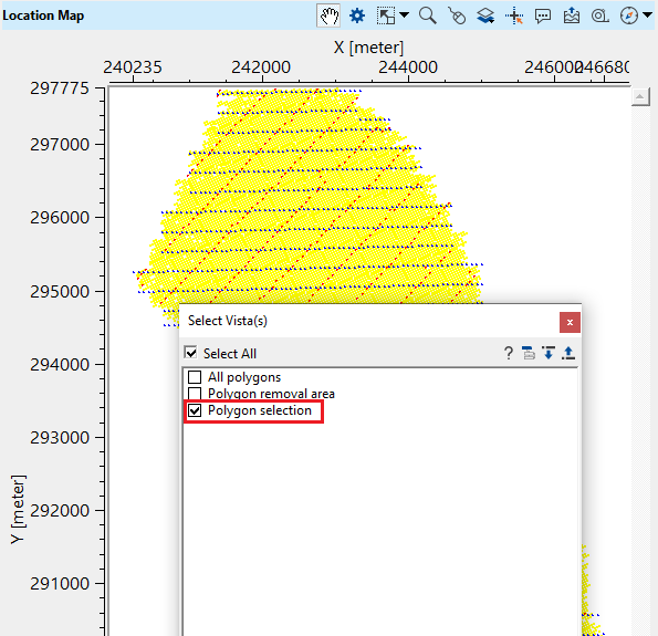
3. Hold Polygon picking module and drag and drop it onto the Location map (Read seismic traces) which was previously added. As soon as, you release the mouse, it will come up with a window. Select "Polygon selection" from the 3 options.
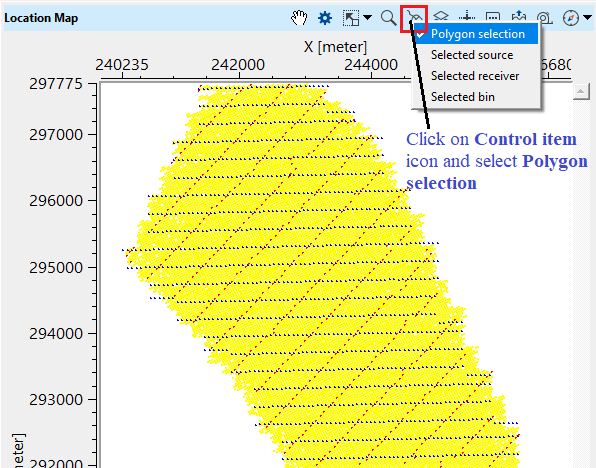
4. Select polygon picking from the Control item icon.
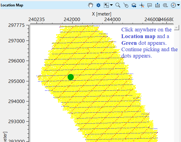
5. Start picking the polygon on the Location map.
6. A pop-up window appears. Give it a name. This name will be the current polygon name appears in the Parameters under Current polygon.
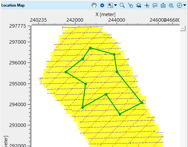
To change the points, simply choose the point and drag it wherever the user wants. In case the user wants to delete any point, simply right click(MB3) on the point and it disappears.
How the same polygon looks like when the current polygon is autodetect and the mode is changed from Convex hull to Concave hull?
Convex hull
Concave hull
If we look at both the convex & concave auto detection of the seismic volume, it looks like this in a zoom version.
Actions
Import polygon from text file
allows the user to import any ASCII/Text format polygon file
Export polygon to text file
allows the user to export the picked polygon in Text format.
------------------------------
Import polygon from CPS3 file
allows the user to import the polygon from CPS3 file format.
Export polygon to CPS3 file
allows the user to export the polygon in CPS3 file format.
------------------------------
Smooth current polygon
by clicking this action item, it will smooth the current polygon.
Revert last smooth
this action item reverses the previously done smoothing.
Video lesson
YouTube video lesson, click here to open [VIDEO IN PROCESS...]
Related articles
Yilmaz. O., 1987, Seismic data processing: Society of Exploration Geophysicist
 * * * If you have any questions, please send an e-mail to: support@geomage.com * * *