 ANISOTROPY PRE STACK DEPTH MIGRATION (APSDM)
ANISOTROPY PRE STACK DEPTH MIGRATION (APSDM)
|
<< Click to Display Table of Contents >> Navigation: »No topics above this level«
|
This module performs 2D/3D time migration of seismic traces before stack. The algorithm is a Kirchhoff integral trace migration where each sample is considered the top of coherent events of a diffracted wave followed by stacking the samples. In other words, Kirchhoff migration estimates diffracted amplitudes by correlating the input seismic data using a calculated model of the diffraction as it would appear if the image point consisted of a diffraction event. All dip and diffraction events are migrated into their real location. Diffraction waves are described by RMS velocities.
The migration process is run in offset classes (user-defined parameters) and requires regularized input seismic data (that can be produced using the Regularization module). Gaps in the offset classes can cause migration operator artifacts. This module reads input seismic data directly from disk and it is unnecessary to load it to RAM. Input seismic data are CMP gathers. Output data are common image gather - CIG.
Execution options: standalone (1 computer execution) and remote (parallel/cluster execution).
Create a new workflow 0400_Inisotrpy_pre-stack_depth_migration: (change picture)
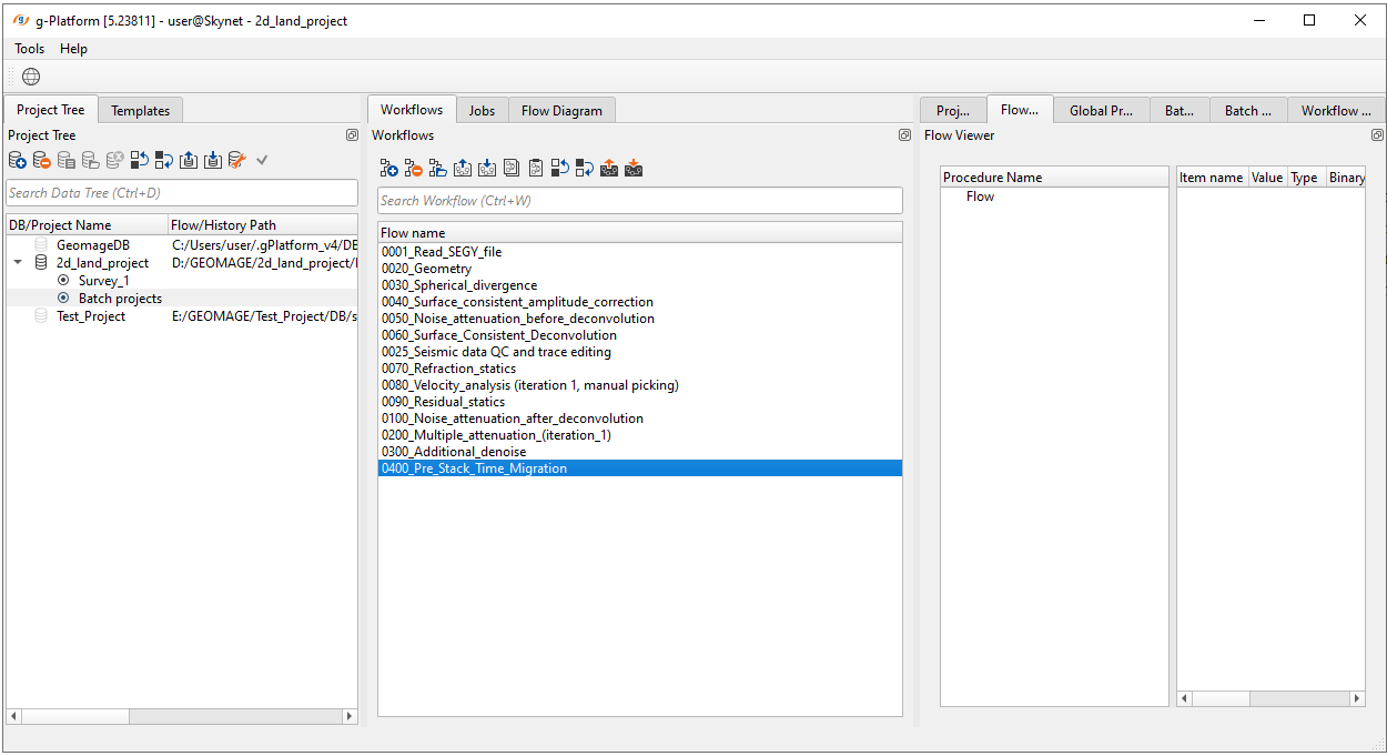
Kirchhoff PreSTM - file in/out - migration
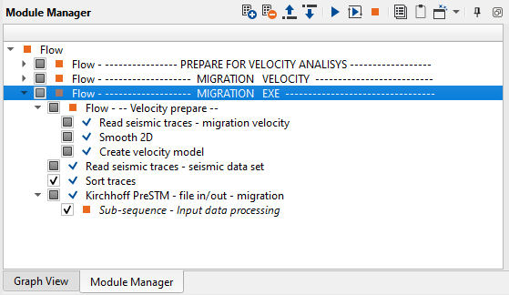
The entire workflow looks a bit complicated, but it is not actually ;-) add all these modules to your workflow:
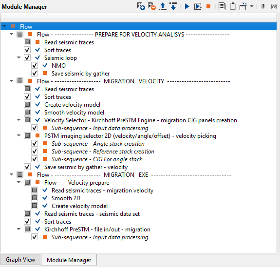
There are 3 main parts:
•Prepare seismic data for velocity analysis;
•Migration velocity analysis;
•Migration execution.
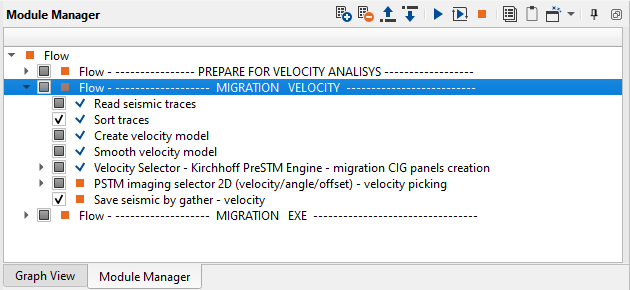
PREPARE DATA FOR VELOCITY ANALYSIS
Part of the workflow for the migration velocity analysis step:
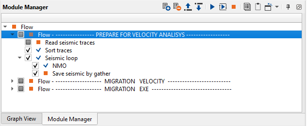
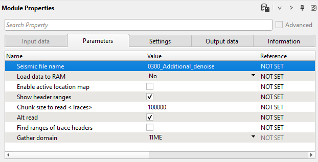
1) Read seismic traces. Load gathers after additional de-noise step 0300_Additional_denoise:
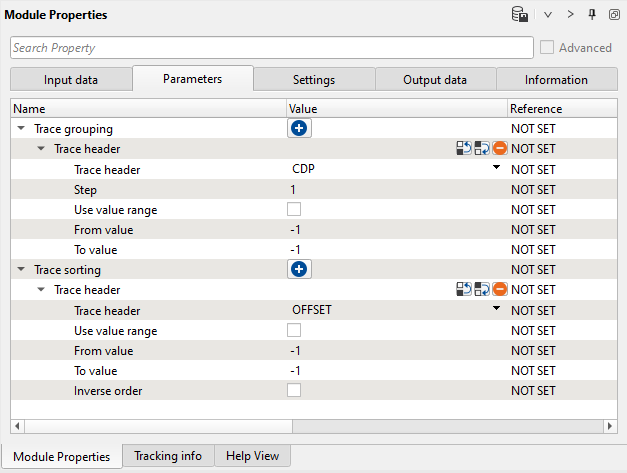
2) Sort traces. Order traces by CDP-offset:
3) Seismic loop. Put NMO and Save seismic by gather modules inside the loop:
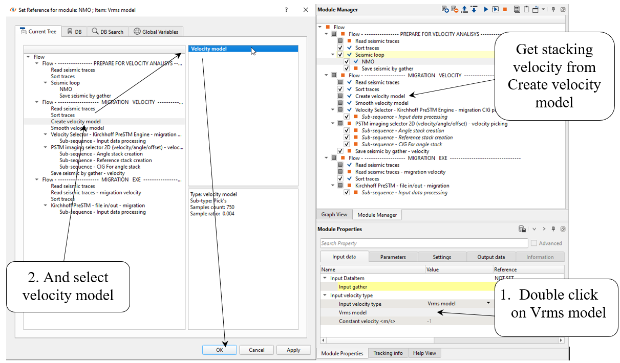
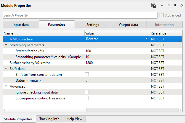
4) NMO. Remove NMO-correction from gathers. Looking ahead, we are going to use velocity from Create velocity module, so you can get parameters from the first screen shot below.
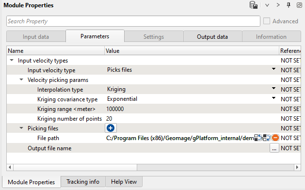
You have velocity pick file on your system (default path):
C:/Program Files (x86)/Geomage/gPlatform_internal/demodata/Poland_2D_Vibroseis_LINE_01/VA_update_afterResidualStatics.corr
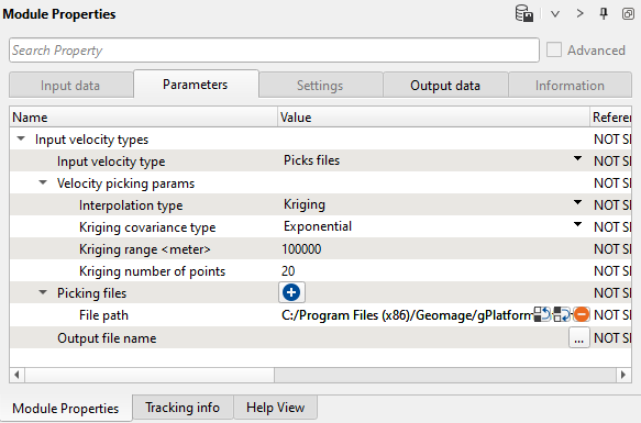
Create velocity model:
NMO:
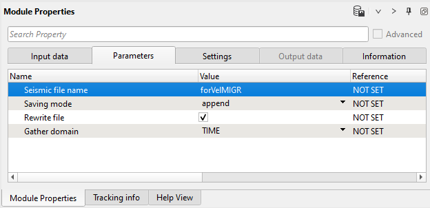
5) Save seismic by gather. Save seismic date set for velocity analysis, define output file name forVelMIGR:
MIGRATION VELOCITY ANALYSIS
Parts of the workflow for migration velocity analysis:
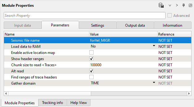
1) Read seismic traces. Load forVel_MIGR seismic data set from the previous part:
2) Sort traces. Order traces by CDP-offset (or use sorting from the previous Sort traces module):

3) Create velocity model. We need this module for importing velocity to the workflow. The module provides different options: import velocity from picking file, from gather, SEGY file, and other formats:
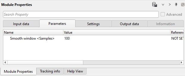
4) Smooth velocity model. Migration requires smoothed velocity model, so if you have quite sharp (rough) picking it is reasonable to make smoothing:
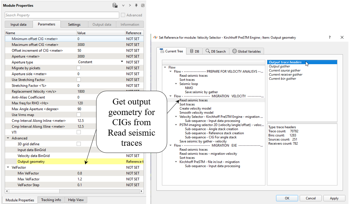
5) Velocity Selector - Kirchhoff PreSTM Engine - migration CIG panels creation. This module performs migration in defined velocity range, or velocity perturbation (min, max, increment). Define input data and parameters:
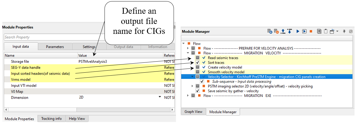
* CIG - Common Image Gather (CMP point after migration).
There is no any output vista windows, so you need just execute this module for preparing seismic data set (CIGs with different velocities).
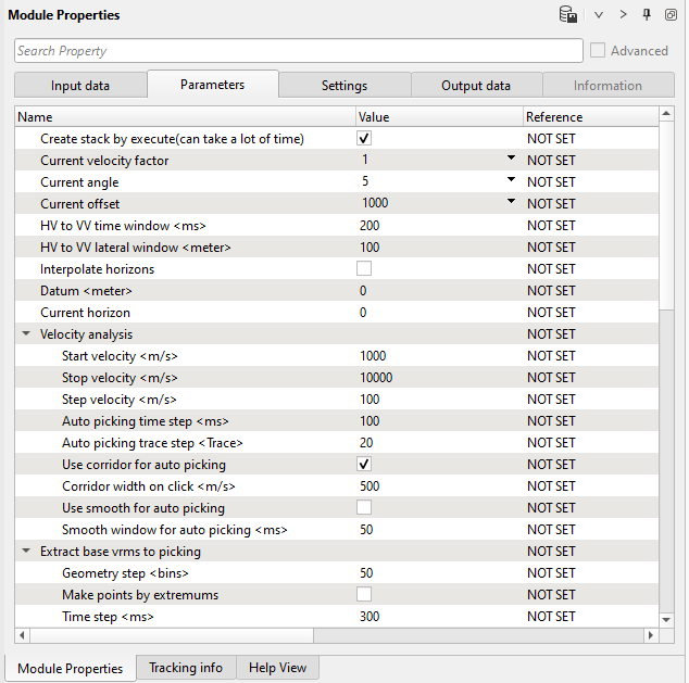
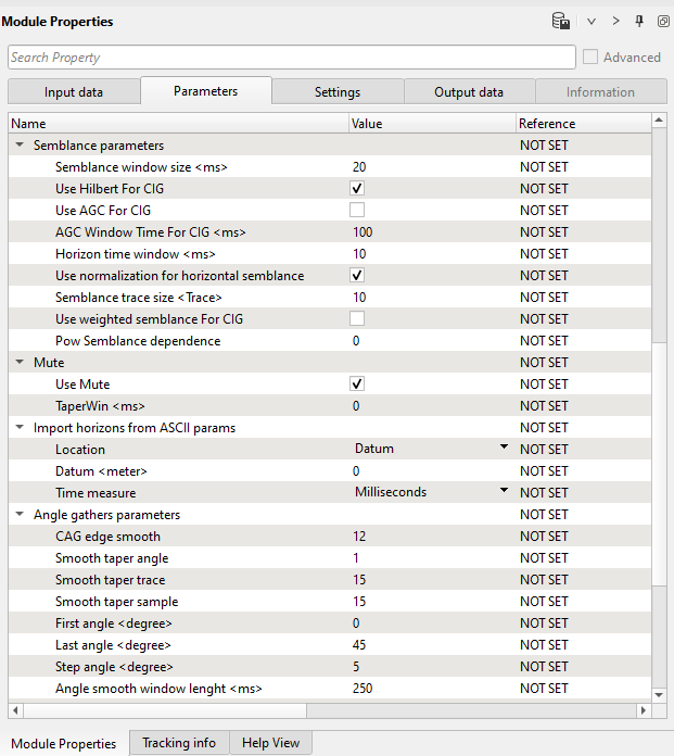
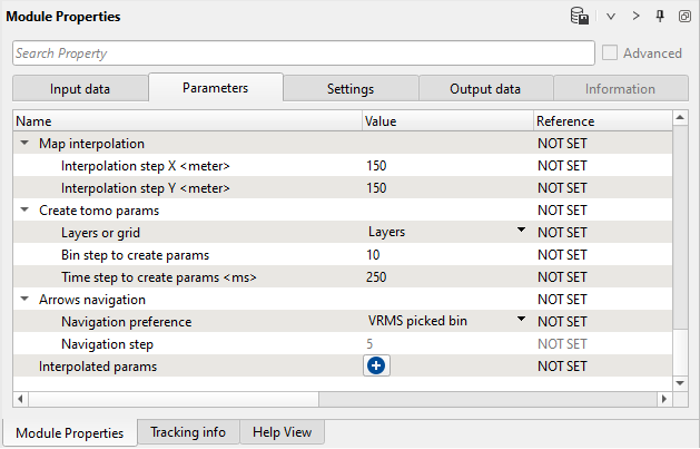
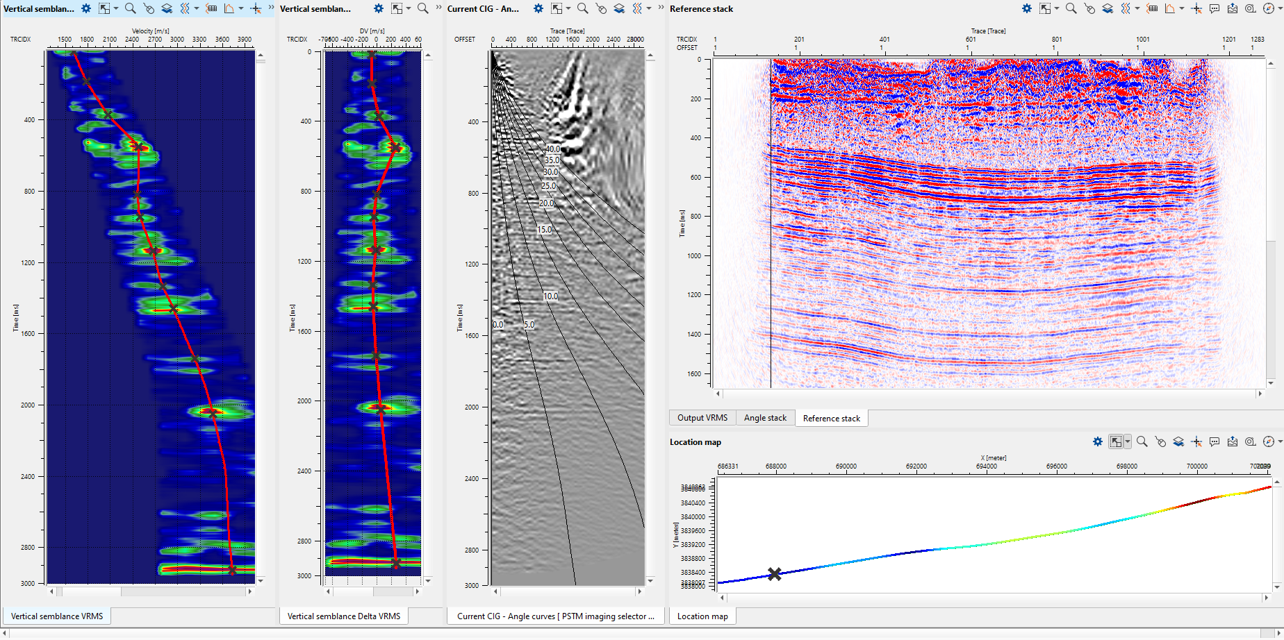
6) PSTM imaging selector 2D (velocity/angle/offset) - velocity picking. The main module in this part of the workflow provides interactive velocity analysis, generating the PSTM Angle stacks, picking vertical Delta Vrms picks, Vertical Vrms velocity picks and Common Image Gathers.
Firstly, we need to get already prepared seismic data set PSTMvelAnalysis3 (CIGs with velocity perturbation):
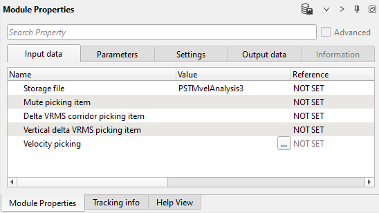
And define parameters:
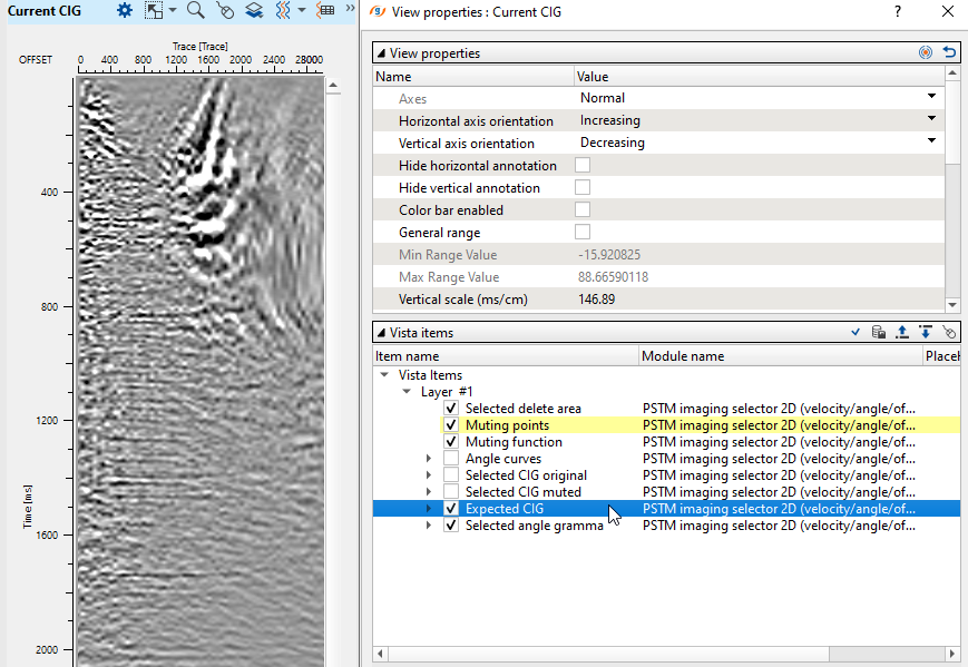
Execute the module and open vista groups and remove some windows that we are not going to use here. You should have the following list of visual windows:
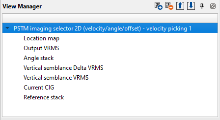
Make all visual setting and window configuration as you wish or try to make the same setup as shown below:
If you have poor stack (low S/N ratio), don't worry, it is because you haven't define a mute function yet.
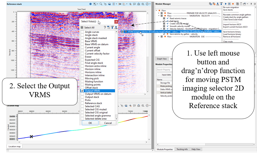
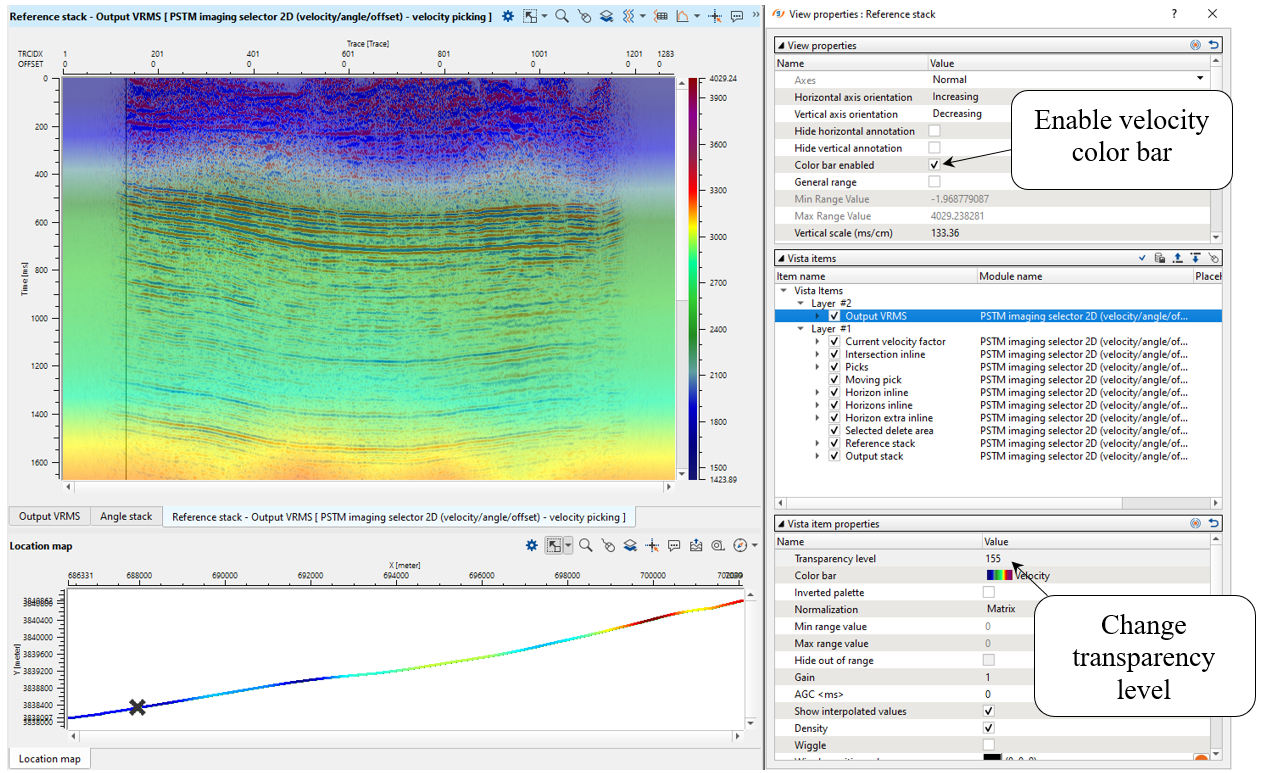
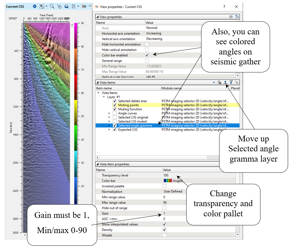
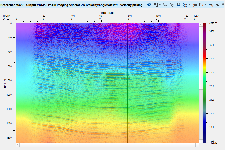
Let's merge seismic stack with velocity, i.e. create an overlaying with transparency:
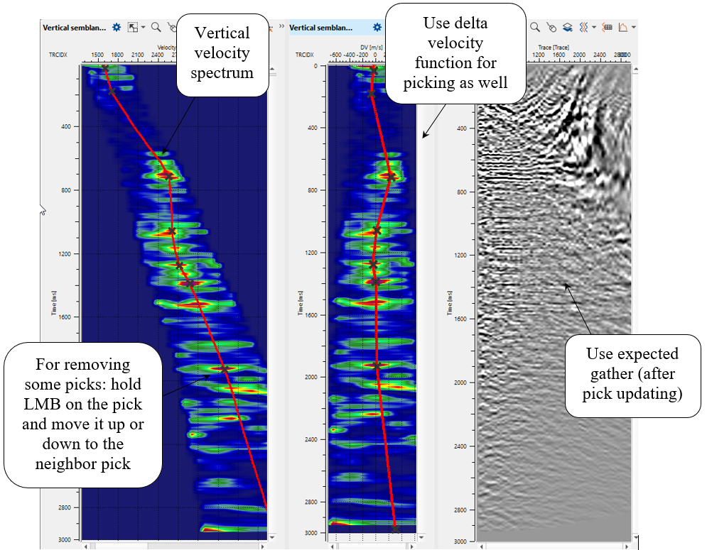
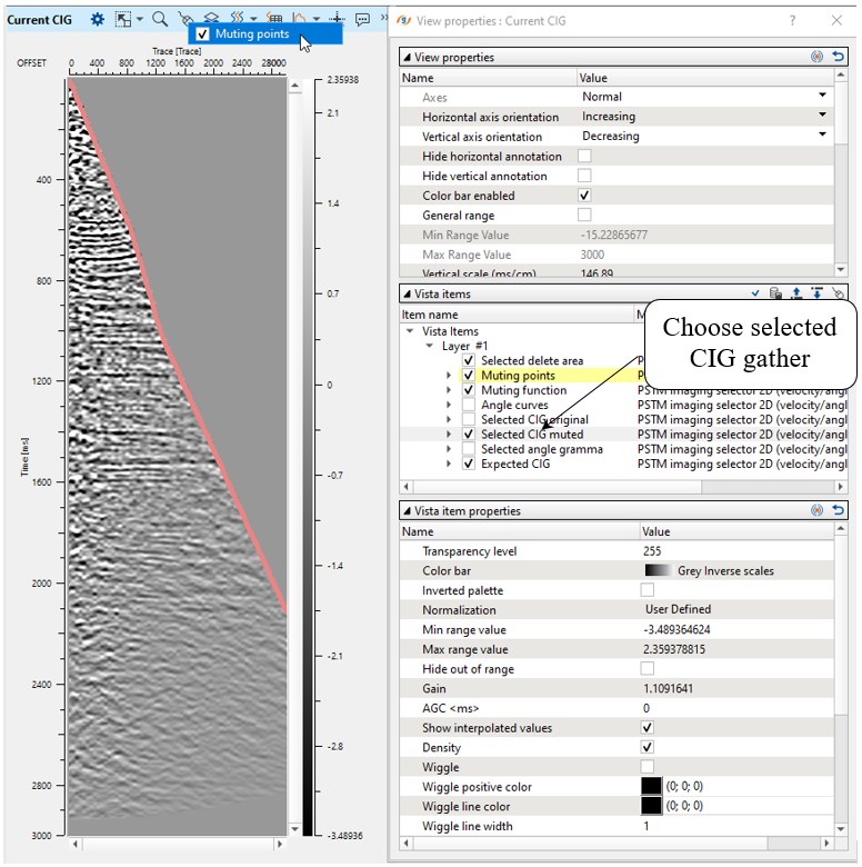
Now we can begin velocity picking, choose any CIG point on the location map and other windows will be updated automatically:
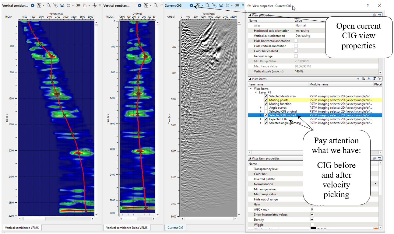
So, activate CIG after velocity updating:
Check angles, we need to know the maximum angle for AVO analysis and final mute function (for gathers):
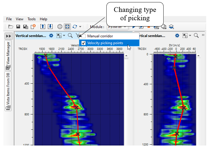
In this case of one 2D line we can make a manual velocity picking. Use option Manual for velocity spectrum, because Corridor is used for auto picking:
For stack we need to create a mute function on CIG gather window. When the mute function is ready you just need to go to the next or previous CIG gather for refreshing a muted gather view:
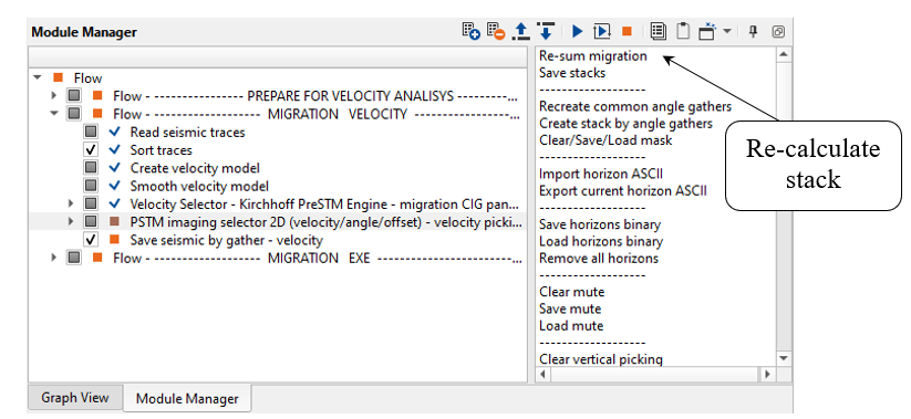
Execute the module for velocity and stack updating.
Don't forget about Action menu, there are many useful functions, like re-build a stack and other:
7) Save seismic by gather - velocity. Now we can save migration velocity gather:
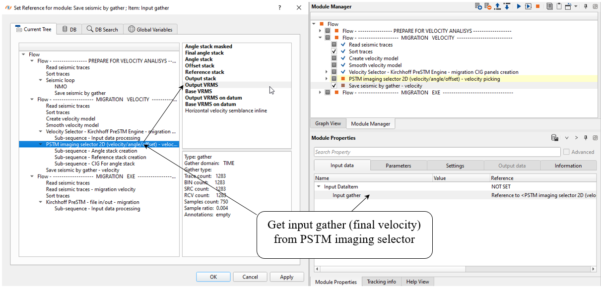
Define an output file name Migration_Velocity:
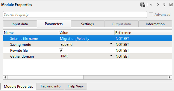
Execute the module.
MIGRATION EXECUTION
The last part of the workflow is for migration execution process:
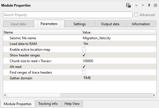
1) Read seismic traces - migration velocity. Read migration velocity as a gather.
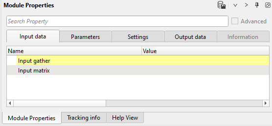
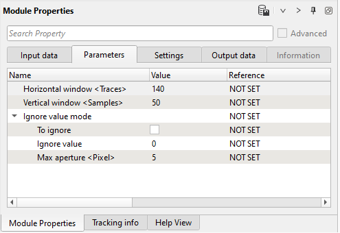
2) Smooth 2D. Time migration algorithm requires quite smooth velocity model in order to avoid operator's artifacts. Therefore, we are going to smooth it via Smooth 2D module. Input data is gather, so connect Input gather parameter with the output gather from Read seismic traces - migration velocity:
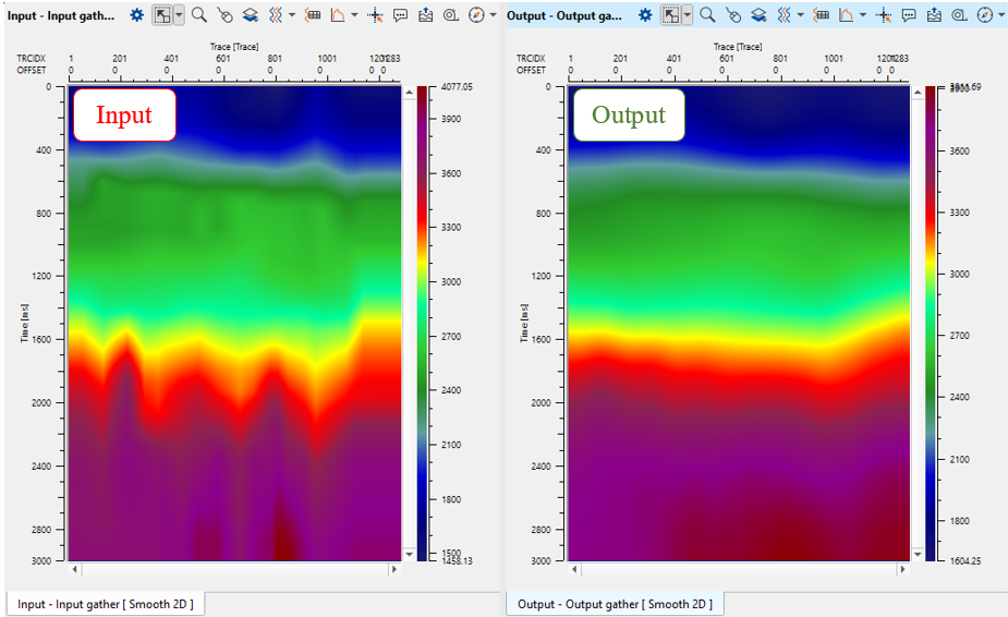
Define vertical and horizontal smoothing, execute the module and open vista views to see input and output velocity model:
Check results:
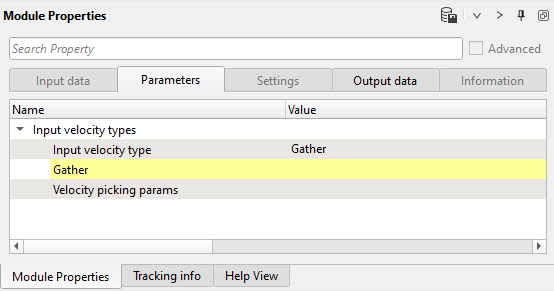
3) Create velocity model. Last step here is converting gathers velocity into a velocity model fro migration module. Execute the modules:
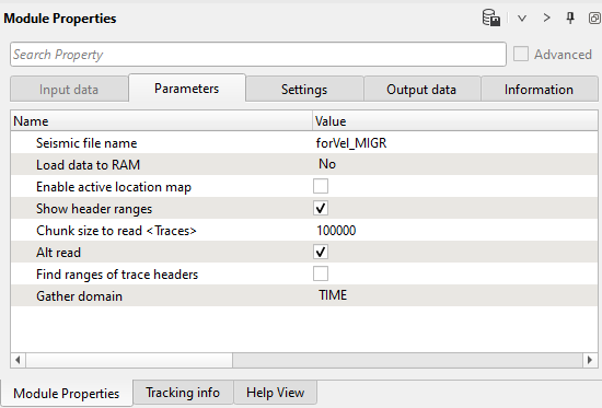
4) Read seismic traces. Load seismic data set for migration. We can use the same file forVelMIGR that we used for velocity analysis, this is seismic traces without NMO corrections:
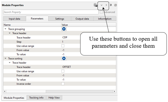
5) Sort traces. Order traces CDP - OFFSET. Pay attention on the buttons that is useful in case of hidden parameters, you can open all of them and close as well:
6) Kirchhoff PreSTM Engine - file in/out - migration. This module performs 2D/3D time migration of seismic traces before stack. The algorithm is a Kirchhoff integral trace migration where each sample is considered the top of coherent events of a diffracted wave followed by stacking the samples. In other words, Kirchhoff migration estimates diffracted amplitudes by correlating the input seismic data using a calculated model of the diffraction as it would appear if the image point consisted of a diffraction event. All dip and diffraction events are migrated into their real location. Diffraction waves are described by RMS velocities. The migration process is run in offset classes (user-defined parameters) and requires regularized input seismic data (that can be produced using the Regularization module). Gaps in the offset classes can cause migration operator artifacts, but it is more about 3D date set and 2D is usually quite regular. This module reads input seismic data directly from disk and it is unnecessary to load it to RAM.
Input seismic data are CMP gathers.
Output data are common image gather - CIG.
Execution options: standalone (1 computer execution) and remote (parallel/cluster execution).
Define parameters. Pay attention that an output file 0400_PSTM you should define here:
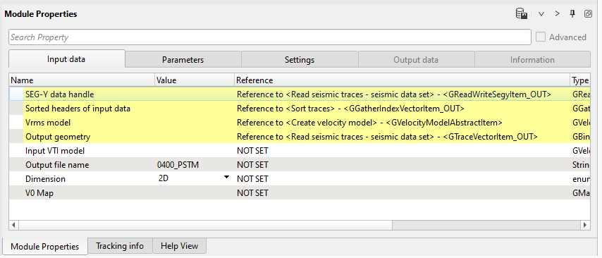
Basic parameters definition:
Input data:
Link to sorted headers of the input seismic traces.
Link to sorted headers of the input velocity traces.
By default the module defines output geometry from Sorted headers of input data.
Output file name
Full path and file name of output SEGY file.
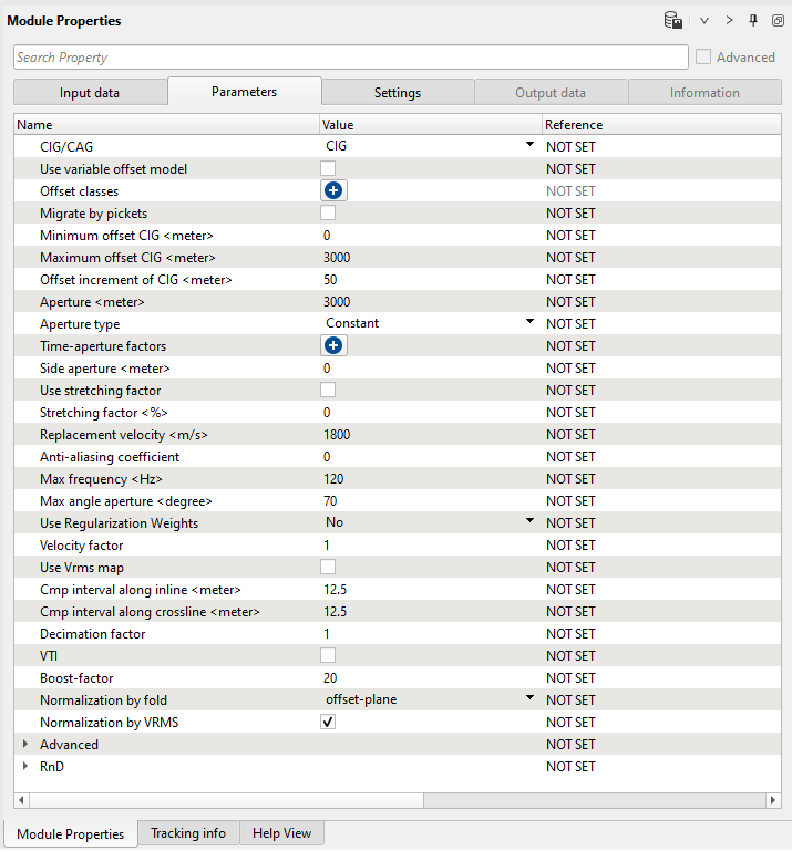
Parameters:
Choose the appropriate output gather type. Depending on the user preference, the final output gather will be either CIG or CAG.
If the offset is irregular, then the user can check this option.
Define the offset classes by clicking on the icon.
This option is useful if it is a straight line where the source and receivers are falling on the same line.
Minimum offset for the common image gather.
Maximum offset for the common image gather.
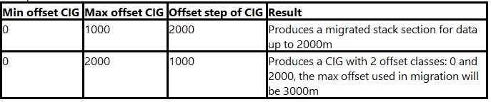
Offset increment for the common image gather. Parameters Max offset and offset step can be used to limit the offset range of the input data. Cases where the Offset step of CIG is larger than the Max offset CIG will produce only 1 offset class with the input data range equal to the Offset step of CIG. In cases where the Offset step of CIG is smaller than the Max offset CIG, the offset of the input data will be equal to the Max offset CIG plus the Offset step of CIG.
Examples:
Migration aperture.
Choose the aperture type. i.e. Constant or Time variant.
If the aperture type is Time Variant then the user should provide the values here.
Distance (meters) from the survey edge. Aperture value will be linearly increased (from 0 to maximum) in this offset range from the edge. Use this parameter to minimized migration operator artifacts along the survey edge.
Stretching muting for migration operator.
Factor for managing the mute zone.
Replacement velocity used to account for topography. Required parameter.
Anti-aliasing filter coefficient. Increasing the coefficient produces a stronger filter (low frequency for far offsets).
Maximum frequency of the output seismic data.
Maximum angle aperture of the migration operator.
By default No. Choose the available options from drop down menu.
Velocity multiplier. By default 1 is used. (100% velocity field used).
By default FALSE.
Bin size along the inline direction. Meters.
Bin size along the crossline direction. Meters.
Define the decimation factor. It is 1 by default i.e. no decimation.
By default FALSE. If user provides the VTI model in the Input data tab, then it should be checked.
Define the value to increase the performance run time so that it will take less time to finish the migration without compromising the quality of the final. output.
Choose the normalization type from the drop down menu. By default None.
Next step >>> Multiple attenuation (iteration 2).
 If you have any questions, please send an e-mail to: support@geomage.com