 | PRE-STACK DEPTH MIGRATION (PSDM) |
| | PRE-STACK DEPTH MIGRATION (PSDM) |
|
<< Click to Display Table of Contents >> Navigation: Tutorials > Seismic Processing 3D LAND >
|
The algorithm is a Kirchhoff integral trace migration where each sample is considered the top of coherent events of a diffracted wave followed by stacking the samples. In other words, Kirchhoff migration estimates diffracted amplitudes by correlating the input seismic data using a calculated model of the diffraction as it would appear if the image point consisted of a diffraction event. All dip and diffraction events are migrated into their real location. Diffraction waves are described by RMS velocities.
The migration process is run in offset classes (user-defined parameters) and requires regularized input seismic data (that can be produced using the Regularization module). Gaps in the offset classes can cause migration operator artifacts. This module reads input seismic data directly from disk and it is unnecessary to load it to RAM. Input seismic data are CMP gathers. Output data are common image gather - CIG.
Execution options: standalone (1 computer execution) and remote (parallel/cluster execution).
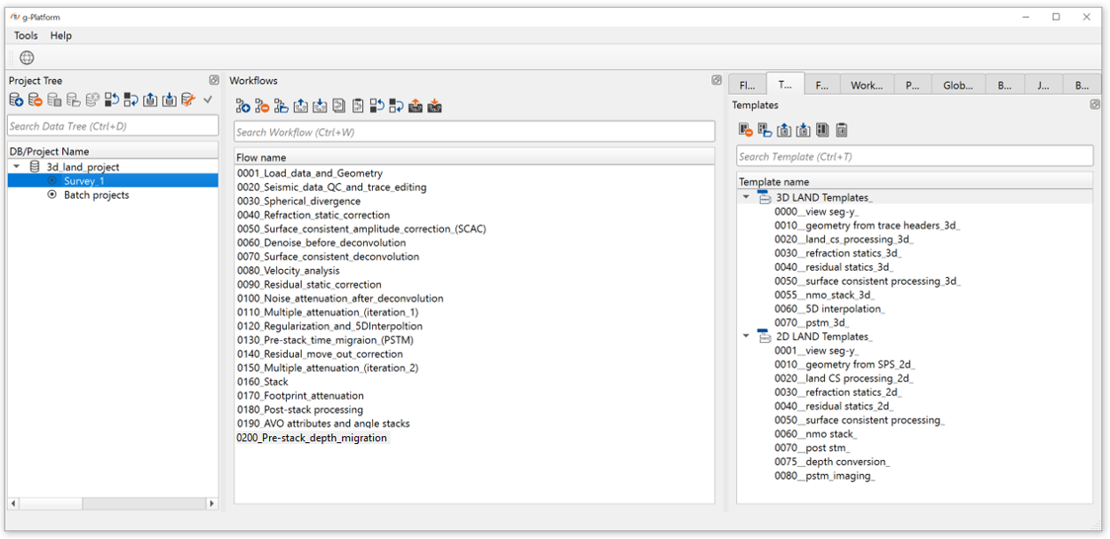
Create a new workflow 0200_Pre-stack_depth_migration_(PSDM):
There are 3 main parts in depth migration:
1) Input data preparation for depth migration;
2) The first iteration of depth migration;
3) The second and next iterations of depth migration.
1) INPUT DATA PREPARATION FOR DEPTH MIGRATION
Part of the workflow for input data (seismic traces + velocity) preparation:
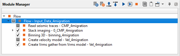
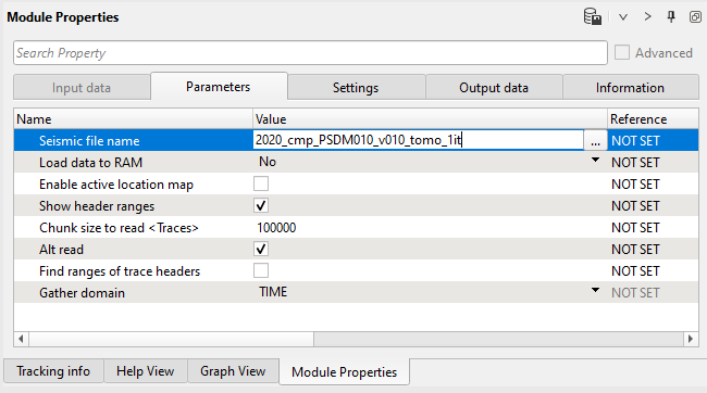
1) Read seismic traces. Load gathers after regularization step 0300_Regularization:
2) Use Stack Imaging to create stacks before migration just for QC purposes.
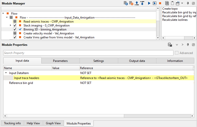
3) Connect Binning 3D module to Read seismic traces and create a 3D grid for migration velocity extrapolation.
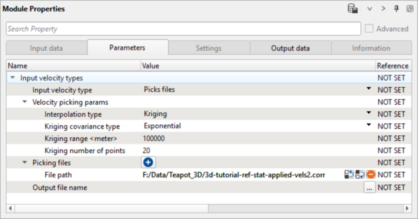
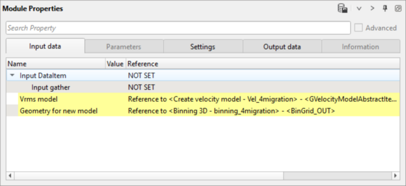
4) Load final velocity into Create velocity model.
5) Connect Create Vrms gather from Vrms model to velocity model and BinGrid.
2) THE FIRST ITERATION DEPTH MIGRATION
The next part of the workflow for 1st iteration of depth migration:
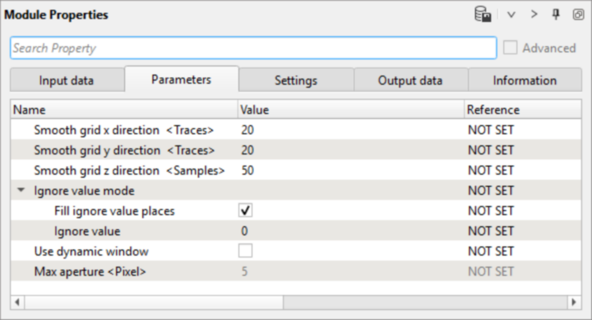
1) Smooth 3D. Depth migration requires smoothed velocity model, so if you have quite sharp (rough) picking it is reasonable to make smoothing:
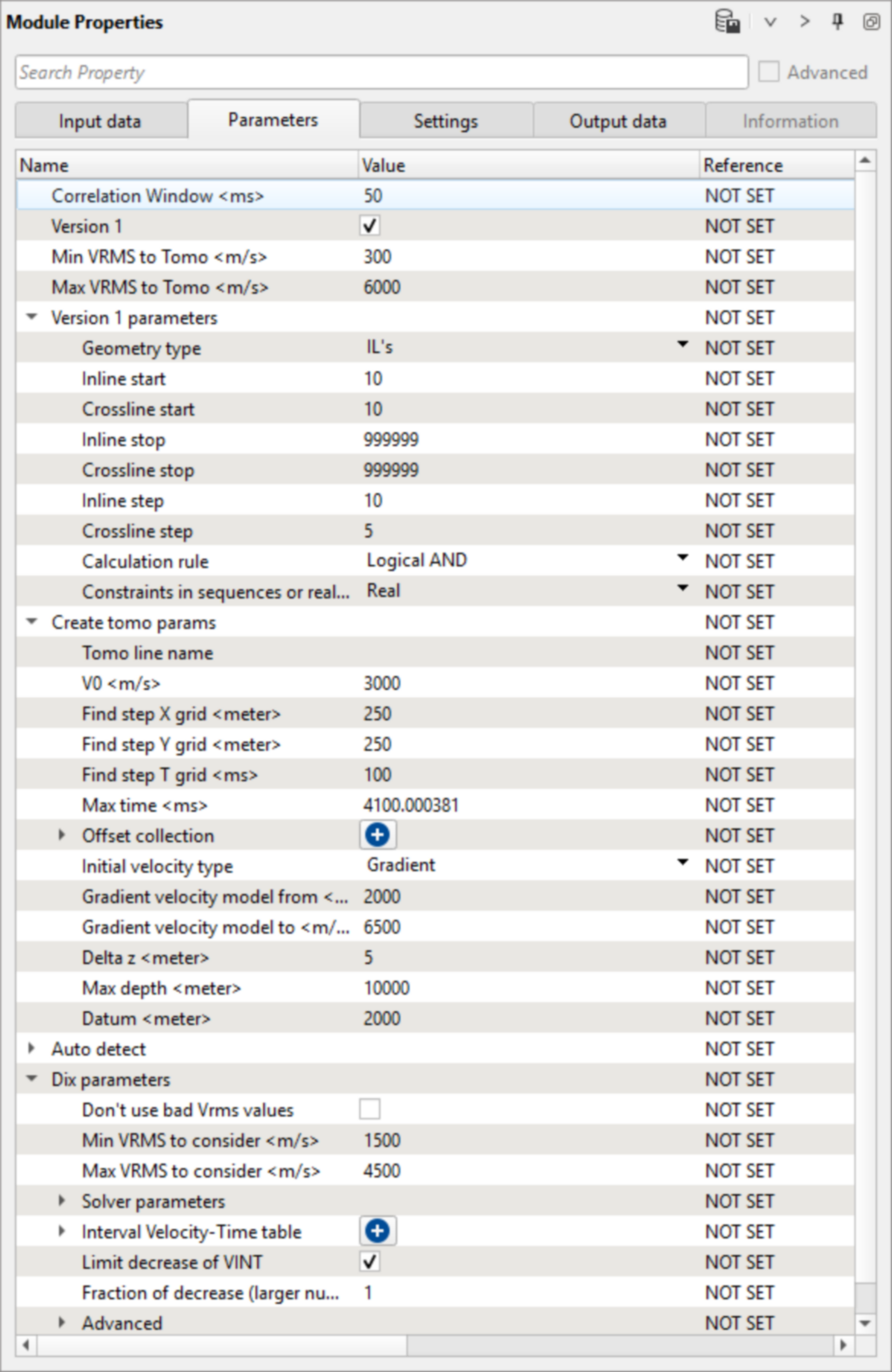
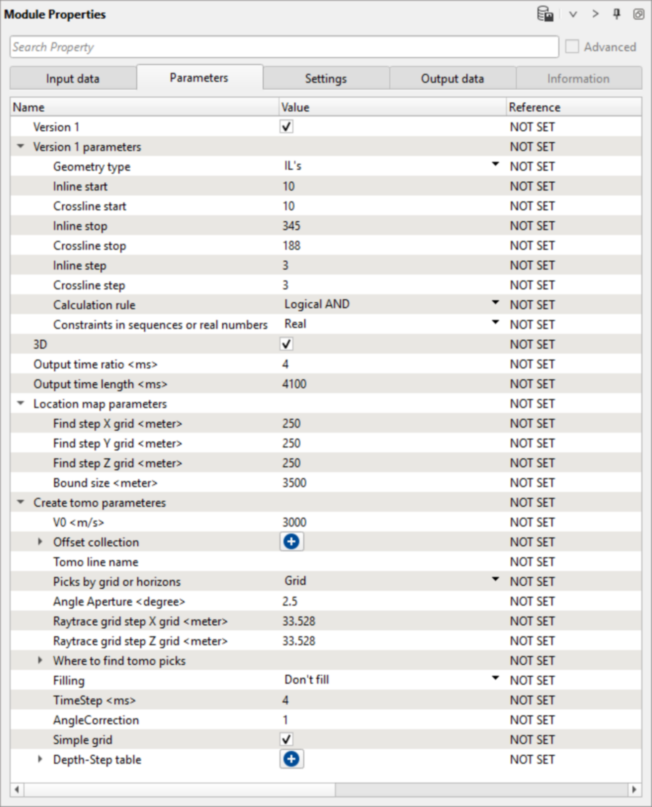
2) Convert smoothed VRMS to stereo 3D tomo parameters. We can use PreSTM velocity to create initial stereotomographic model. The stereotomographic model is a velocity macro-model with a set of pairs of ray segments associated with each picked event such as the ray shooting angles from event towards some source and receiver and corresponding two one-way travel times. For the rational use of computing resources, we calculate the tomo parameters on the grid inline and crossline. Pay attention on inline and crossline start/stop/step, because these parameters lead to the resulting amount of tomography skeleton:
3) Stereo tomography multiline (test) creates depth velocity model from the initial tomography database. Stereo tomography is based on Ray tracing. The basis of the Stereo Tomography concept is to recognize any locally coherent events characterized by their travel times and local slopes (two slopes) in the prestack data to provide some information about velocity model. The locally coherent events can be interpreted as pairs of ray segments and provide the velocity information independently. This module is used to generate the updated velocity models. We generate the Tomo items from the VRMS to stereo 3D tomo parameters or PSDM Imaging modules. This module perform tomography on the skeleton model: inlines and crosslines with a particular step that was defined in the VRMS to stereo 3D tomo parameters module (previous step).
At the moment, tomography is calculated by lines. To combine the calculated tomographic lines, we should use a few extra modules as shown below:
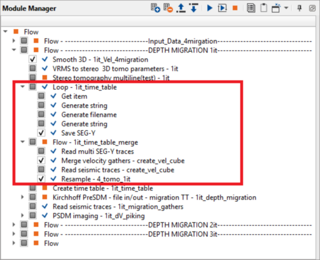
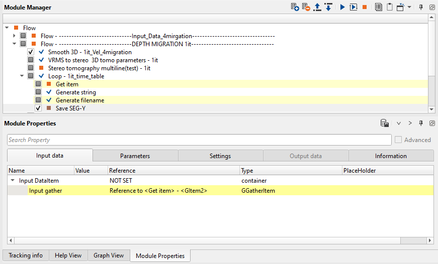
First, we need to save resulting tomography inlines and crosslines on a disk. This part requires to use file mask creating for inlines and crosslines auto-naming (for more details please see Batch execution tutorial). We should run Loop - 1it_time_table mini-flow (all lines via ![]() ) which is consist of the following modules:
) which is consist of the following modules:
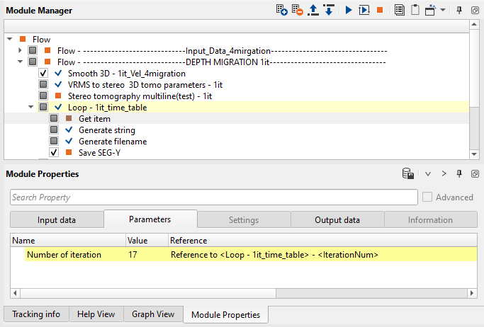
•Loop:
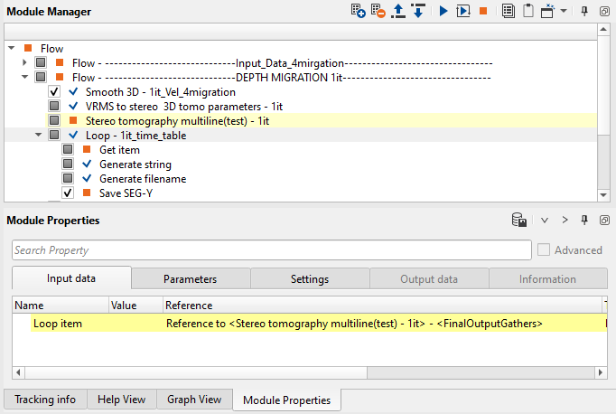
•Get item:
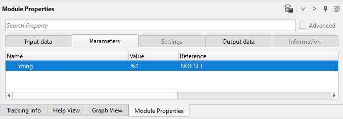
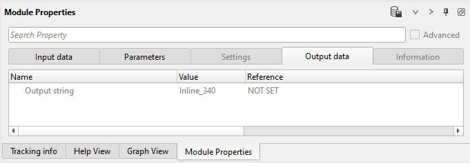
•Generate string
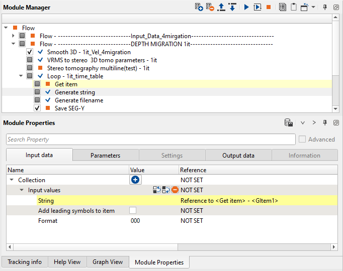
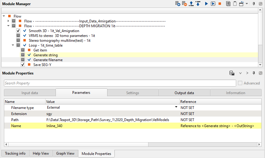
•Generate filename
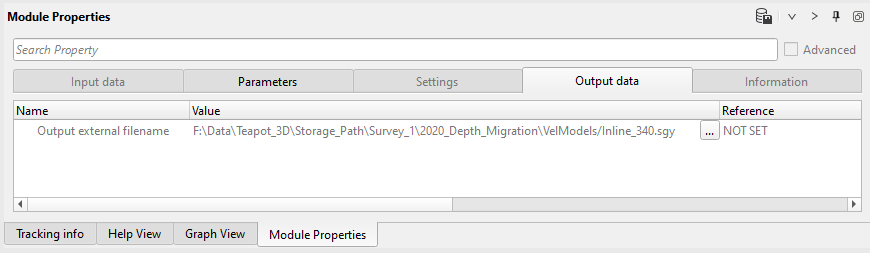
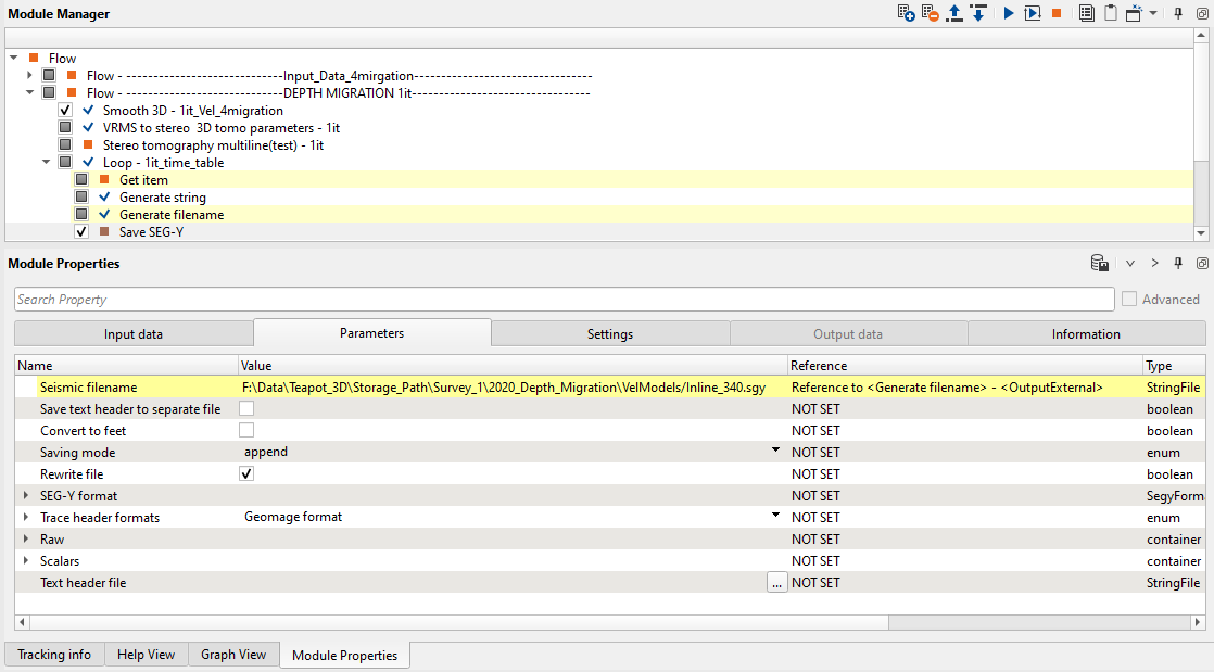
•Save SEG-Y
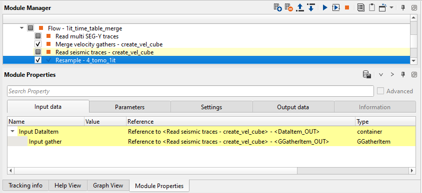
Second, we need to merge resulting tomography inlines and crosslines into single file by using the next mini-flow Loop - 1it_time_table, which is consist of the following modules:
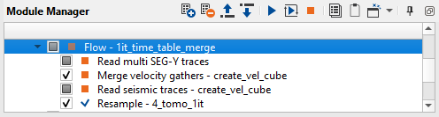
•Read multi SEG-Y traces:
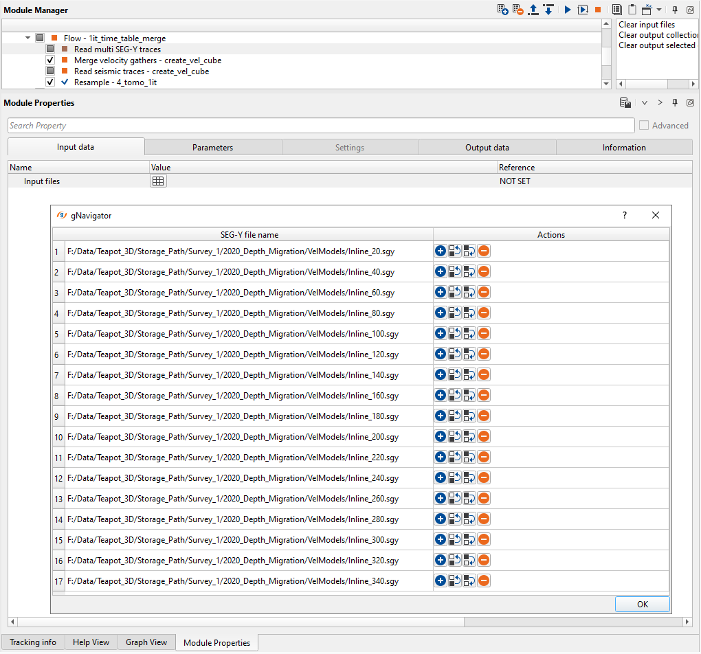
•Merge velocity gathers - create_vel_cube:
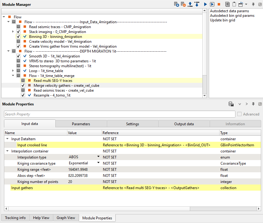
•Read seismic races - create_vel_cube:
•Resample - 4_tomo_1it:
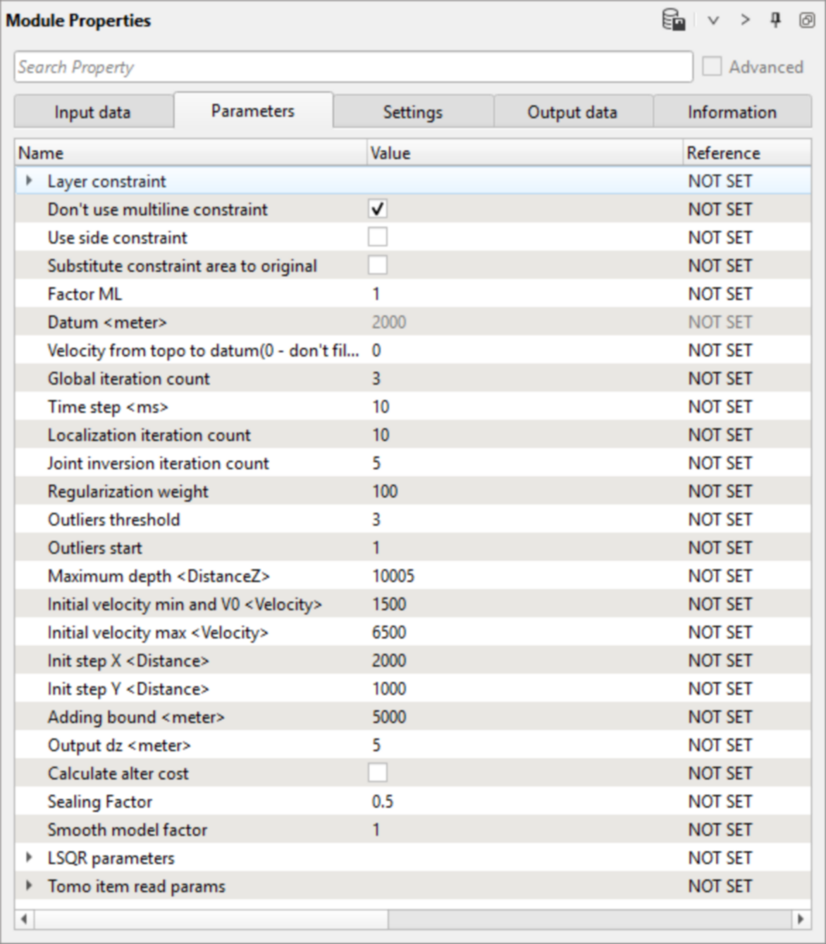
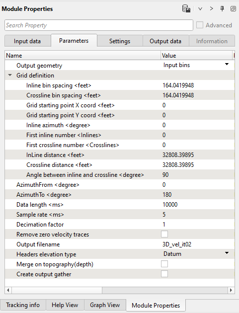
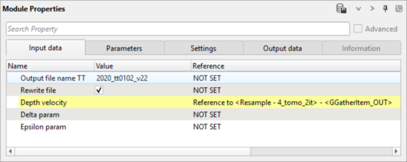
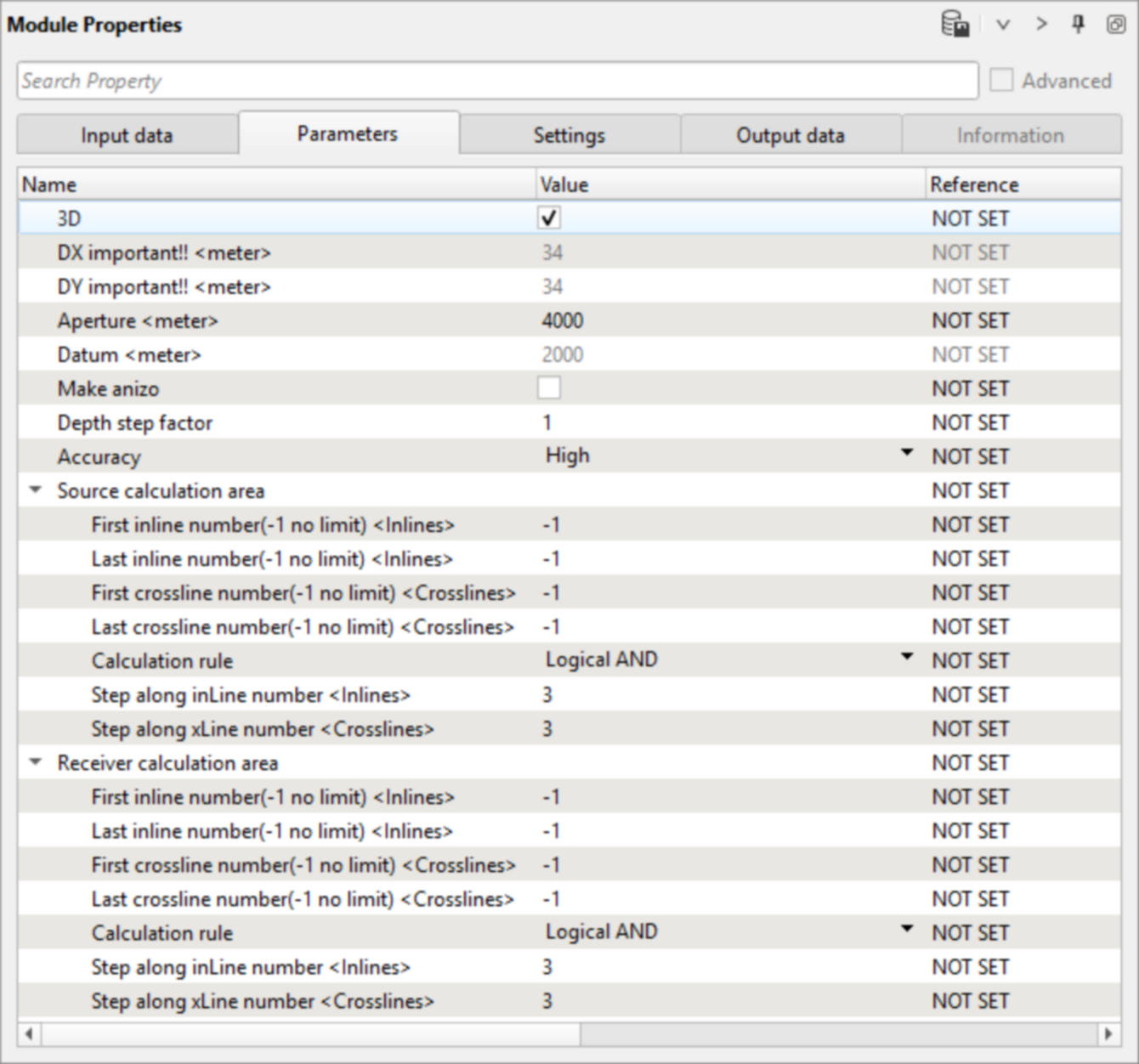
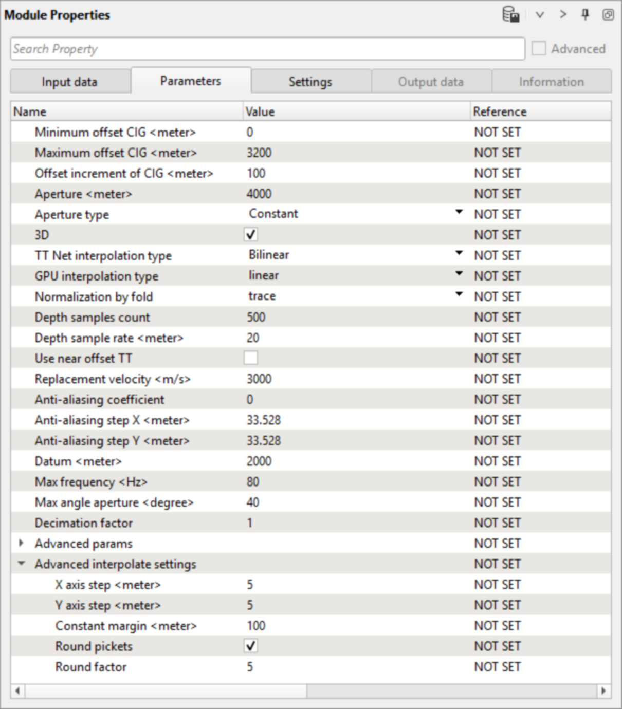
4) Create time table for depth migration. This table contains information about all possible wave travel times from one model cell to neighboring. These tables are calculated based on the velocity model and are required to calculate depth migration. Use Resampled cube from Stereo tomography. Decrease Step along Inlines & Crosslines for more accurate migration.
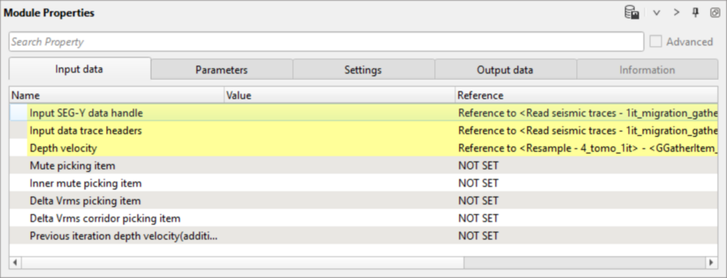
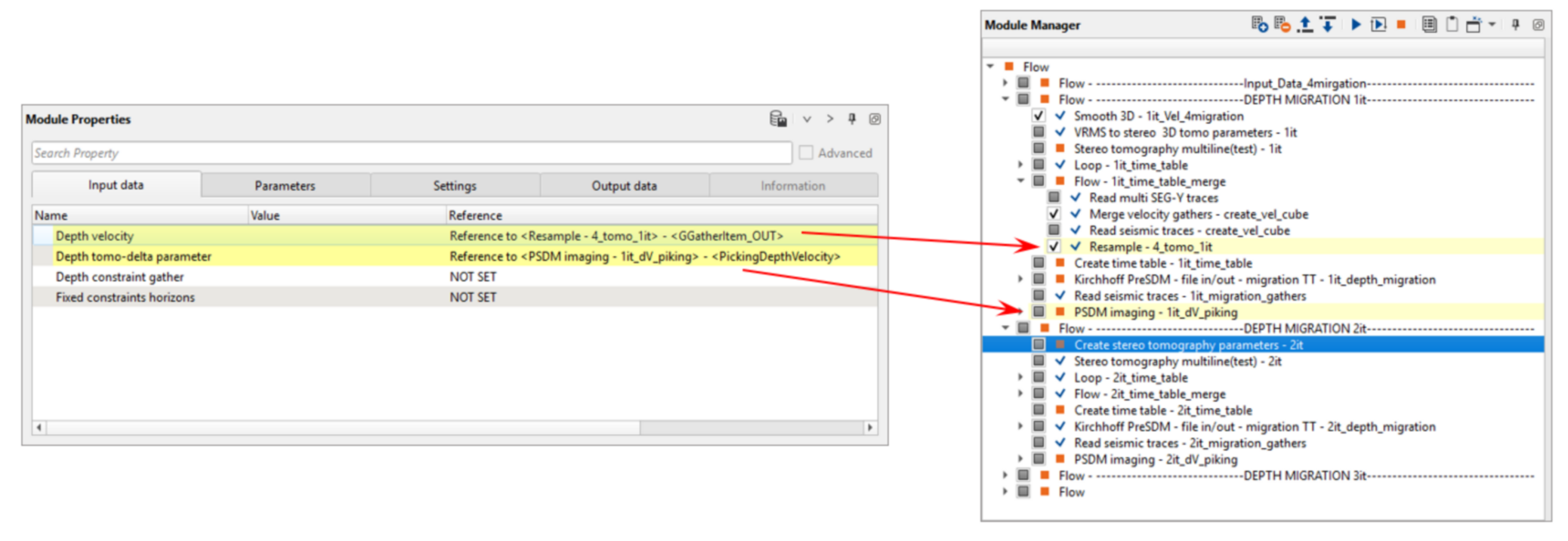
5) Kirchhoff PreSDM - file in/out - migration TT. This module performs depth migration using depth velocity model after Stereo tomography and Create time tables. Define input data and parameters:
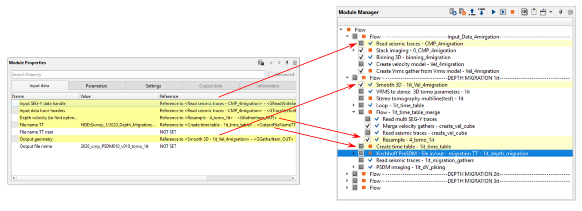
* DCIG - Common Image Gather (CMP point after depth migration).
There is no any output vista windows, so you need just execute this module to get data after 1st iteration of depth migration (DCIGs).
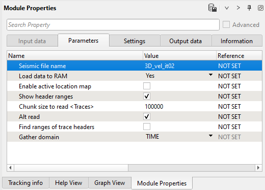
6) Read seismic traces. Read DCIGs after Kirchhoff PreSDM - file in/out - migration TT.
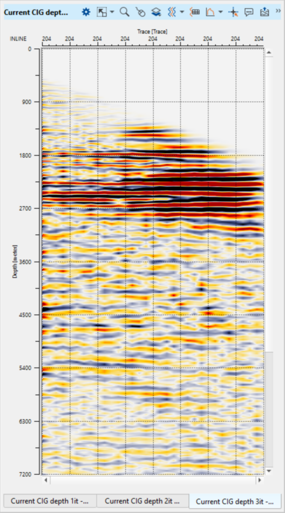
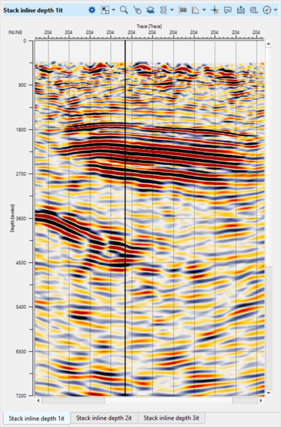
7) PSDM imaging. The main module in this part of the workflow provides interactive velocity analysis, generating the PSDM stacks, Depth Common Image Gathers, Delta DM semblances and picking Delta V.
Firstly, we need to get already prepared seismic data set with DCIGs:
And define parameters:
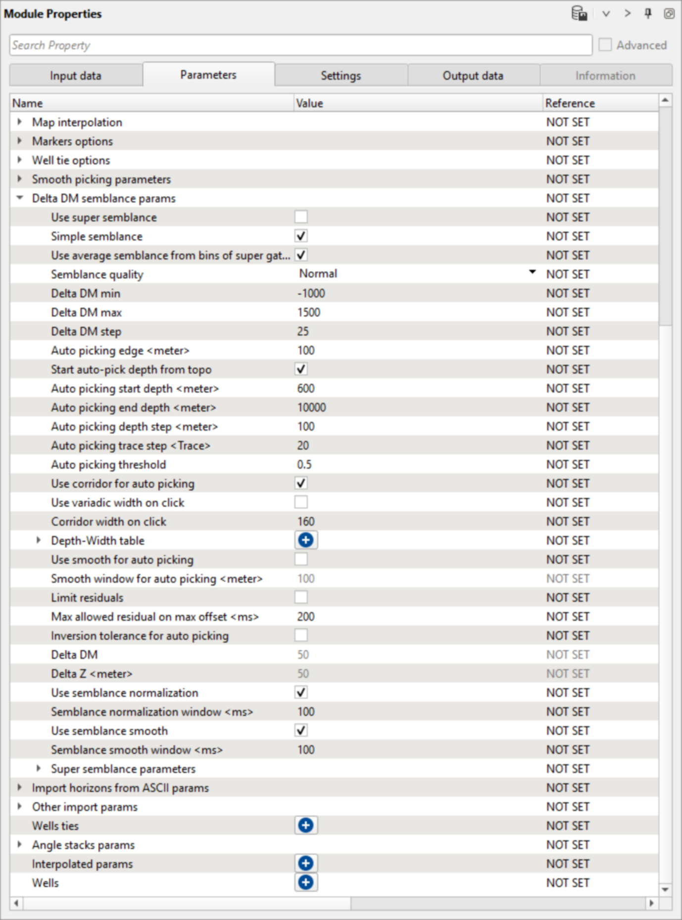
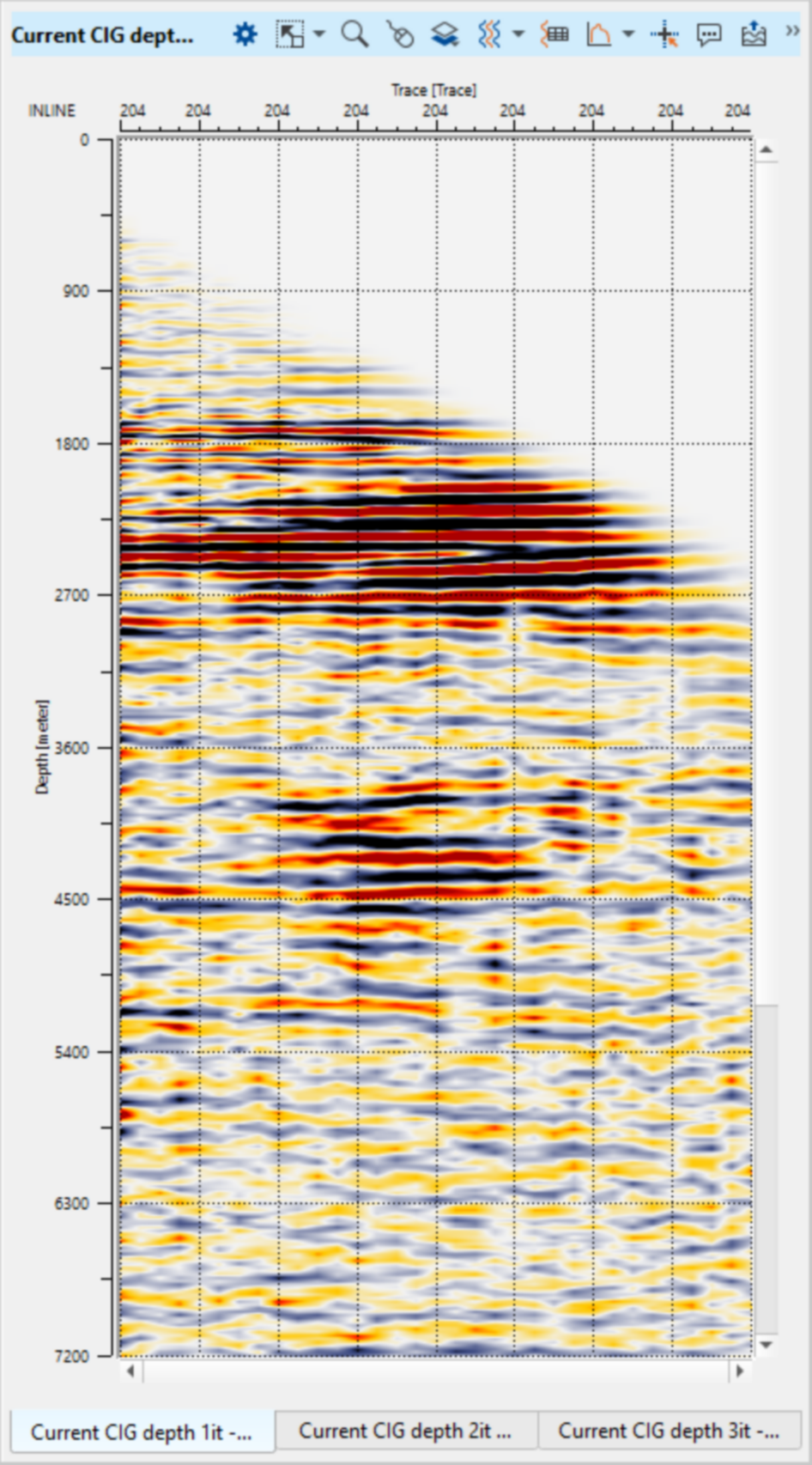
Execute the module and open vista groups and remove some windows that we are not going to use here. You should have the following list of visual windows. Make all visual setting and window configuration as you wish or try to make the same setup as shown below:
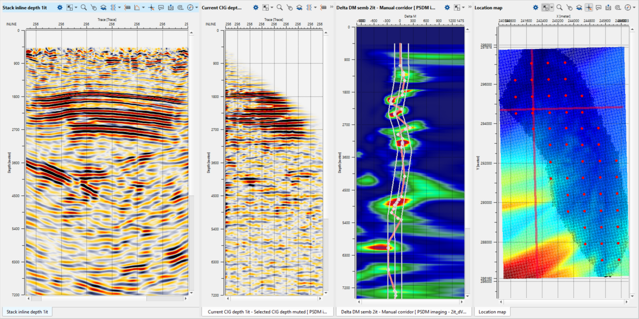
Use Current CIG depth vista to pick outside mute and rerun the module. Now you should get a depth stack without migrations stretching. Now we can begin velocity picking, choose any CIG point on the location map and other windows will be updated automatically. So, activate Delta DM semblance view, choose Manual corridor in set control item and pick it along a line.
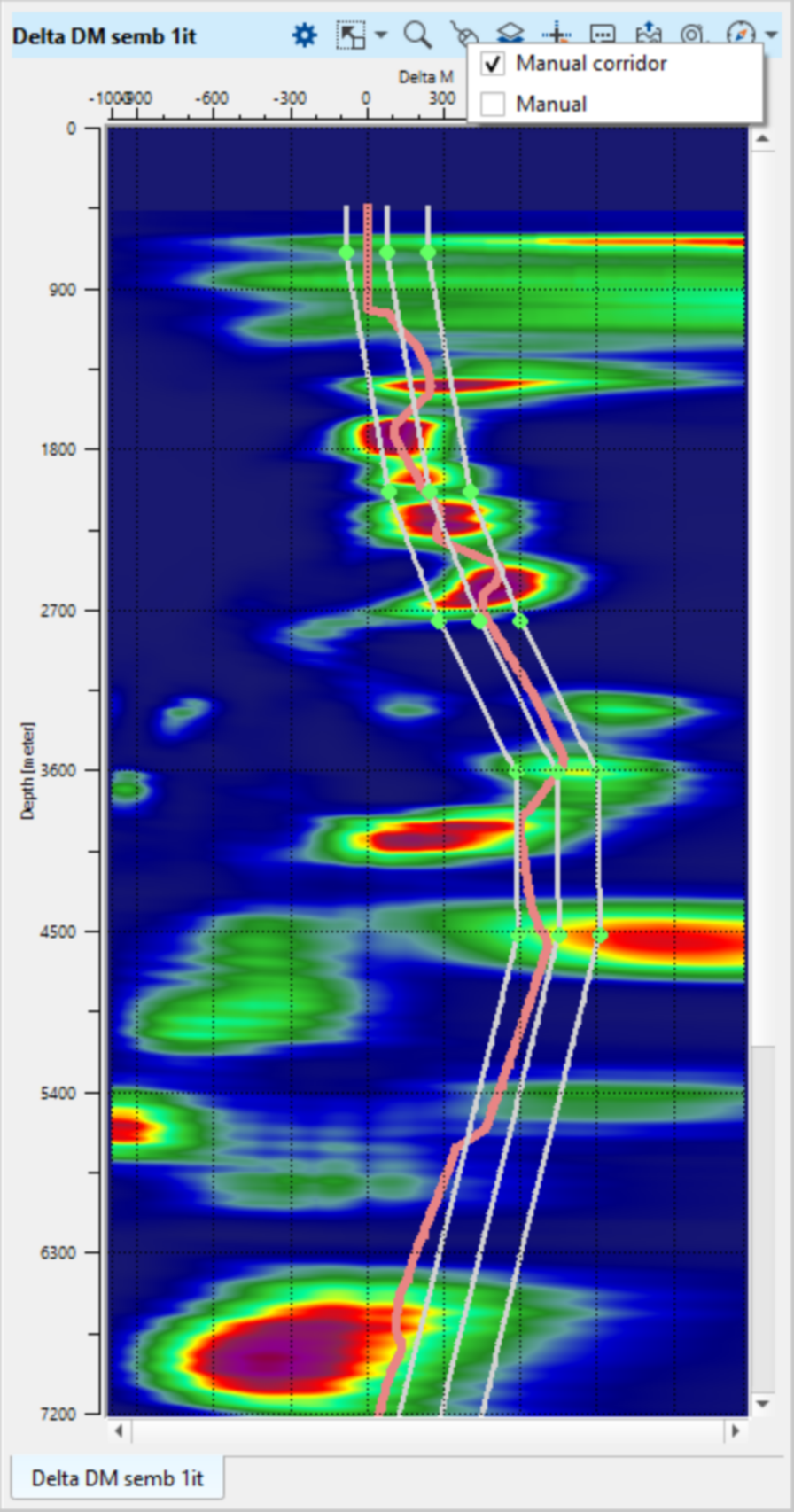
In case of small 3D survey we can also make a manual velocity picking. Try option Manual for velocity spectrum, Corridor is used for next auto picking. To save or load mute, DM or corridor piking use Action menu:
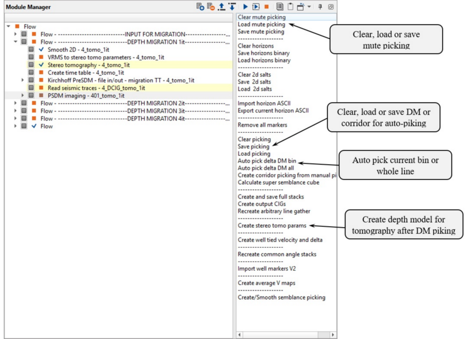
Use this menu to pick DM on current bin or whole survey manually or automatic.
SECOND AND NEXT ITERATIONS OF DEPTH MIGRATION
The next part of the workflow for 2nd iteration of depth migration:
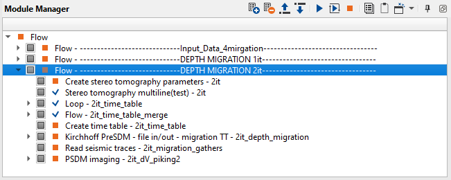
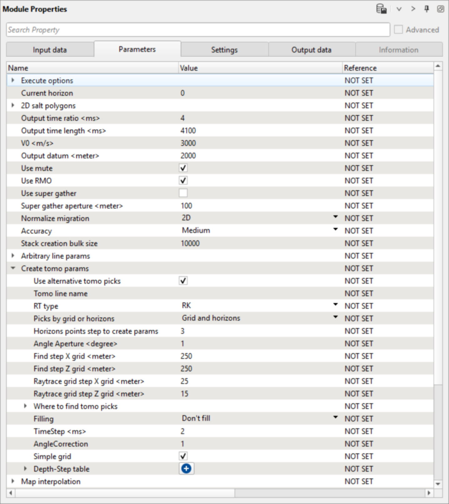
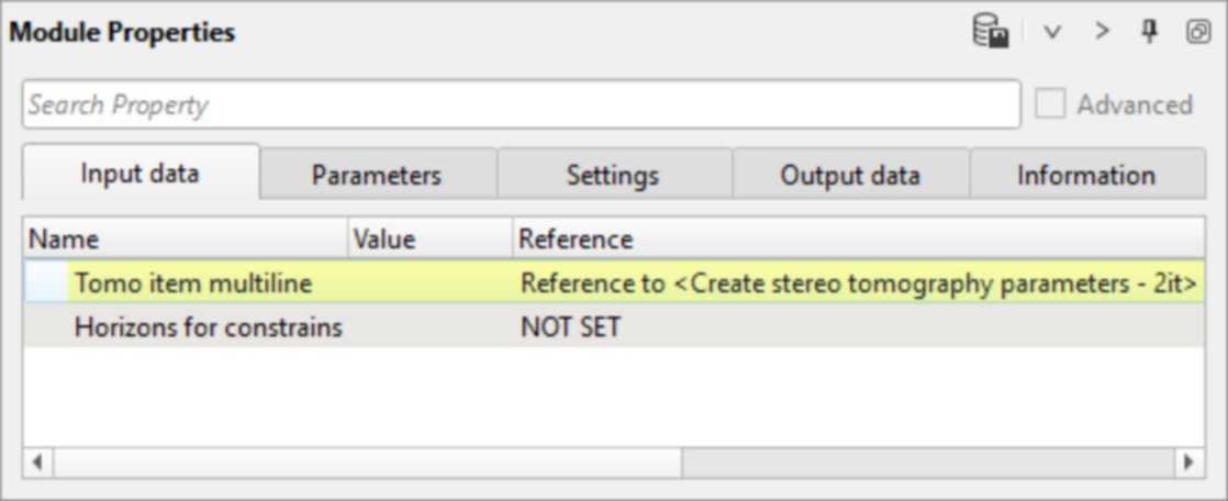
1) Create stereo tomography parameters. Create tomography parameters from initial velocity model and picked delta velocities of 1st iteration of PSDM imaging. Inline and crossline grid for tomography can be made denser for more accurate calculations.
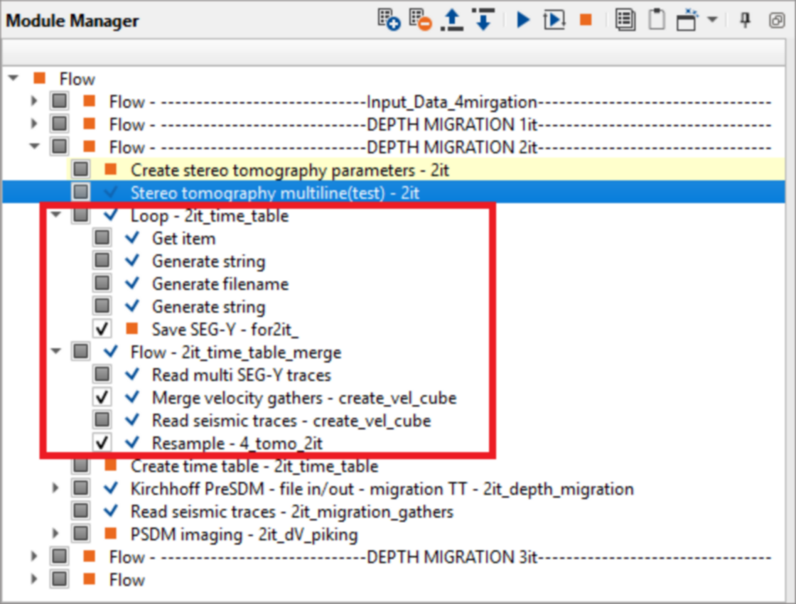
2) Stereo tomography multiline (test). Use second iteration Create stereo tomography parameters as input for 2nd iteration of stereo tomography. All parameters can be save from previous iteration. Use additional modules (red frame) to combine Inlines after stereo tomography as showed in previous iteration.
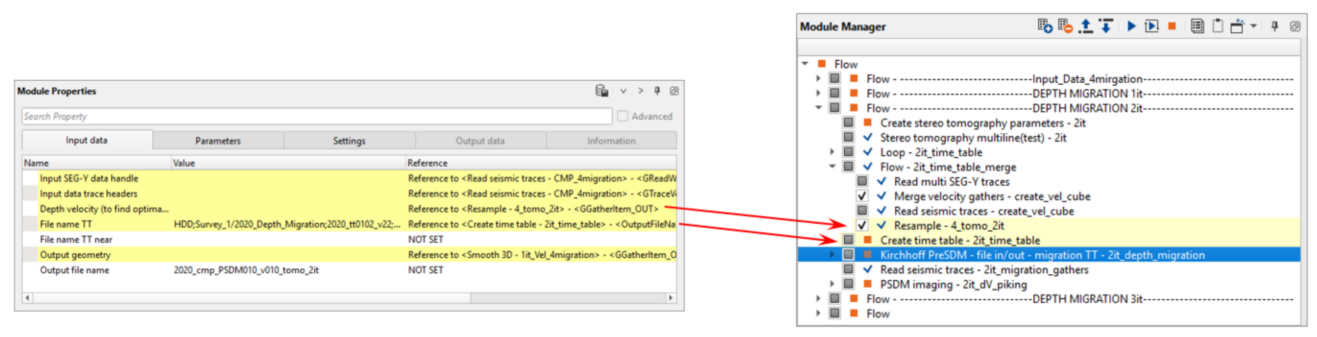
3) Create time table second iteration. Use Resampled cube from second Stereo tomography.
4) Kirchhoff PreSDM - file in/out - migration TT. Use depth velocity model after Stereo tomography and Create time tables after 2nd iteration. Define input data as show on picture, find appropriate parameters for your data:
5) Read seismic traces. Read DCIGs after Kirchhoff PreSDM - file in/out - migration TT 2nd iteration.
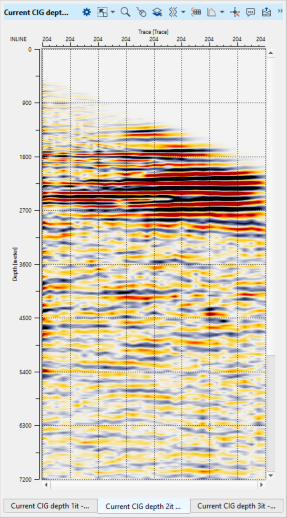
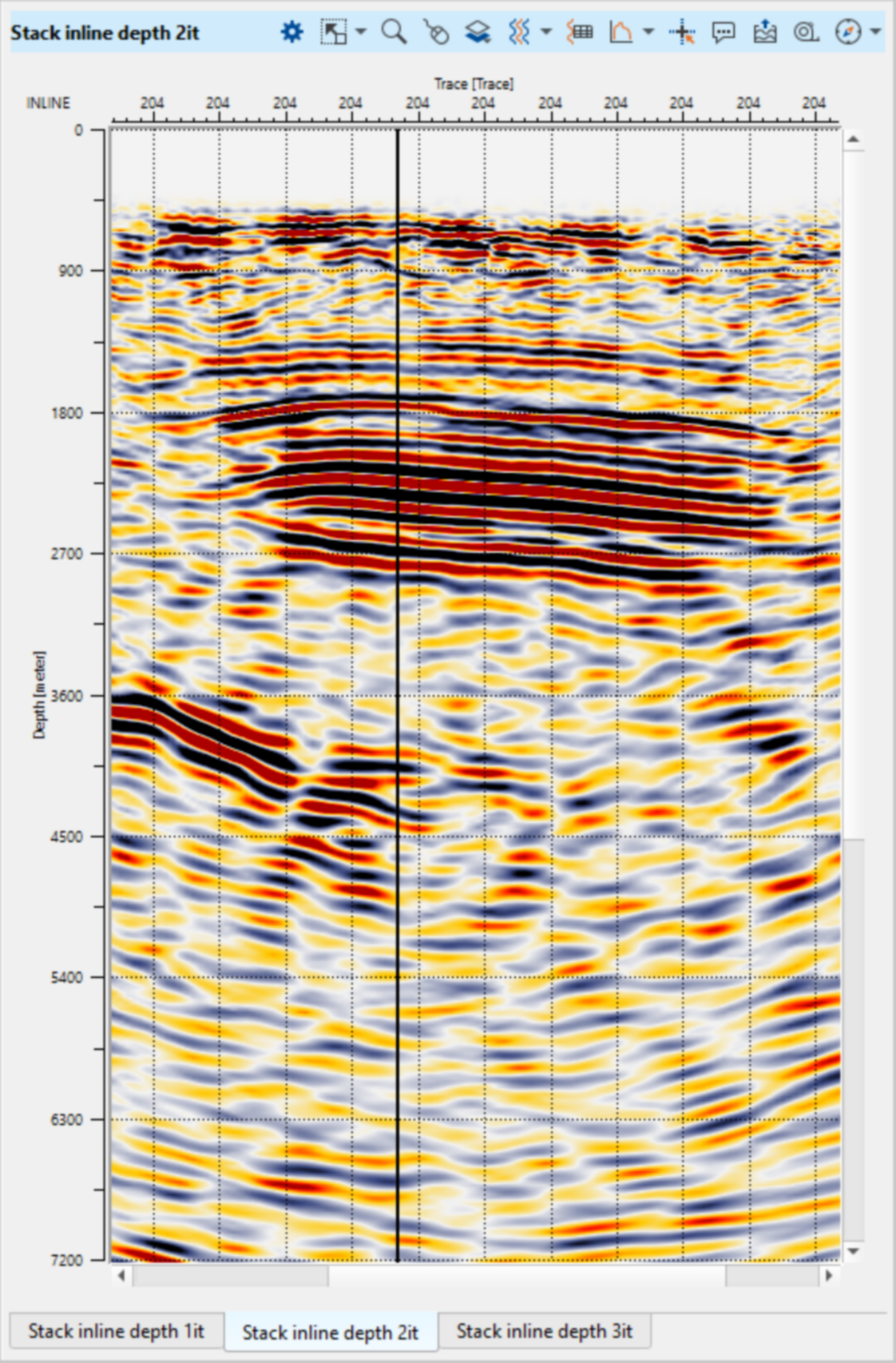
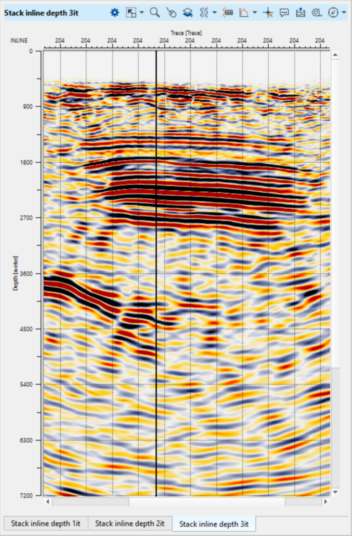
6) PSDM imaging second iteration. At the second and next iterations of depth migration repeat all steps from fist iteration to get updated velocity model and Tomo item. And then use this model for next iteration same way as the previous step. After each depth migration iteration you should get DCIG’s gathers with more flattered events and better stacks. Stop depth velocity updates after receiving CDIG’s with flat events and DM semblances with spectra’s close to zero. For not complicated geology usually need to run about 3-4 iteration, in case of complex geology needs to apply much more iteration to get accurate velocity model.
Pay attention on near offsets, it is better to reduce it due to the fact that seismic traces are contaminated by harsh noise on near offsets. Since we have depth CIG data set, there is the same processing flow for post migration stage. Use Stretch depth to time module for depth to time conversion.
 If you have any questions, please send an e-mail to: support@geomage.com