First breaks picking, velocity model creation and static calculation
![]()
![]()
This module computes the static correction based on the first breaks of the data. It allows the user to interactively pick or correct the automatically picked first breaks. Subsequently, the first breaks can be used for refraction static solution, generating static corrections for source and receiver positions. The module calculates only the refraction correction, that is, replacing the near surface low velocity layers from the surface to the bottom of the calculated near surface. The module does not include an elevation correction. Elevation static is a shift which moves the data from topography to final datum. This correction to final datum is performed with a separate module Shift Data. Since most processes in g-Platform that would require the statics applied (for example NMO) can be run from topography, being able to easily separate the refraction correction from the final datum correction is very useful. How to use floating and constant datum planes will be discussed in Datum planes chapter.
Refraction FB picking uses first breaks and parameters for the solver to calculate the source and receiver static correction at each surface location. The solver includes options to calculate a smoothed solution, as well as to solve into multiple azimuths. Additionally, a residual correction can be calculated and applied at each source and receiver giving a short-wave correction. The replacement velocity is calculated internally by the module. Upcoming changes will allow specify a weathering velocity as well as a replacement velocity. With these parameters the module will build a near surface weathering model and then the user defined values will be used for static corrections calculation.
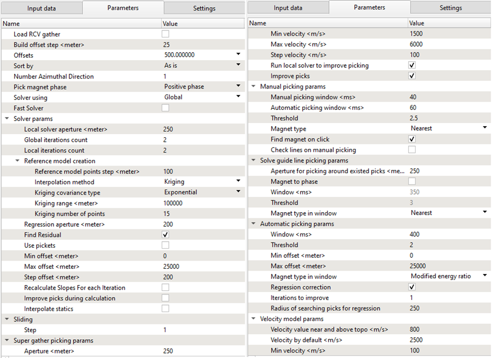
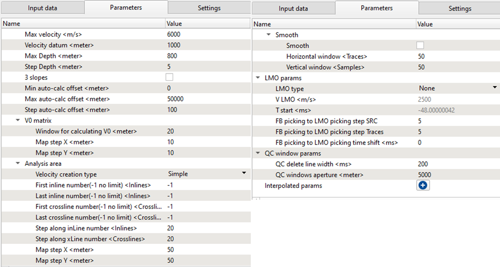
Fill the Refraction FB picking – azimuthal solver guide / phase / aperture parameters before performing calculation and displaying the data set. For the training seismic data set we will use the following example, but you should do some extra tests by changing parameters for better understanding:
![]()
![]()
Load RCV gather
By default it is FALSE. If checked, it will display the receiver gathers in the current receiver gather window.
Build offset step
Provide the offset step size. Depending on the offset step size, it will build the offset classes that can be chosen from the Offsets option parameter.
Offsets
Select the desired offset from the available drop down menu.
Sort by
By default, AS IS. If the user wants to sort the data in a different domain they can do so by selecting the respective options from the drop down menu.
Number Azimuthal Direction
By default 1. In case of 3D, the user can define the azimuths.
Pick magnet phase
Provide the phase to pick the first break
Solver using
Choose the options from Global or Local.
Fast Solver
By default, FALSE. If the user selects, it will compute the solution bit faster.
Solver params
Local solver aperture
Aperture to be used for the local solver
Global iterations count
Total number of iterations used by the global refraction statics solver
Local iterations count
Total number of iterations used by the Local refraction statics solver
Reference model creation
This parameter used during creation of general(smoothed) map of static shifts (built by ABOS algorithm). As bigger the step, bigger the smooth of the map. Note, that while reducing the step, the duration of the process might be substantially increased. Participate in creation of both: low and high(residual) frequency statics models.
Interpolation method
There are two interpolation methods available. Kriging and Abos. By default, Kriging
Kriging covariance type
Select the covariance type from the drop down menu. By default, Exponential
Kriging range
Default: 100000
Kriging number of points
Default: 15
Regression aperture
This aperture used for regression solution ( function thru picked points ). So, that way all picked points related to CDPs within given radius aperture take part in creation of low-frequency statics model.
Find Residual
Find residual static
Use pickets
Min offset
Provide the min offset value for picking the first breaks.
Max offset
The user can limit the minimum and/or maximum offset values. Provide the maximum offset value for picking the first breaks.
Step offset
Offset step size
Recalculate Slopes For each Iteration
By default, FALSE. If checked, it will recalculate the slopes for each iteration.
Improve picks during calculation
By default, FALSE.
Interpolate statics
By default, FALSE.
Sliding
Provide the sliding value to jump to next source/receiver gather
Super gather picking params
Improve picks – Set picks more accurate on phase if it possible
Aperture
Super Gather Aperture, the aperture of locations that will be picked on either side of the current pick
Min velocity
Minimum velocity range for super gather picking
Max velocity
Maximum velocity range for super gather picking
Step velocity
Step velocity between minimum and maximum to be used for super gather picking
Run local solver to improve picking
Leave checked to use the results of the local refraction statics solver to improve the results of your super gather picking
Improve picks
Set picks to be more accurate on the phase if possible
Manual picking params
Manual picking window
Search window used for manual first break picks
Automatic picking window
Search window used for in automatic super gather picking mode
Threshold
Threshold for manual picking
Magnet type
Phase of first breaks to be picked
Find magnet on click
Type of energy for first breaks
Check lines on manual picking
By default TRUE
Solve guide line picking params
Aperture for picking around existed picks
Provide the aperture value for picking first breaks using the solve guide line with existing picks.
Magnet to phase
Choose the phase for picking the first breaks. By default, FALSE. If checked, the next two parameters Window and Threshold will activate.
Window
Provide the picking window
Threshold
Define the threshold. By default 3
Magnet type in window
By default, Nearest
Automatic picking params
Search window for automatic first break picking
Threshold
Provide the picking threshold value for automatic picking
Min offset
Provide the minimum offset value for first break picking
Max offset
Provide the maximum offset value for first break picking
Magnet type in window
There are multiple magnet types are available for first breaking picking. By default, Nearest.
Regression correction
By default, FALSE. If checked, next two parameters will be activated.
Iterations to improve
Provide the number of iterations to improve the regression correction.
Radius of searching picks for regression
Provide the search radius
Velocity model params
Weathering velocity
Weathering Velocity for Refraction Statics correction
Replacement velocity
Specify the replacement value
Min velocity
Define the minimum velocity value
Max velocity
Define the maximum velocity value
Velocity datum
Provide the velocity datum value
Max Depth
Specify the maximum depth of the velocity model
Step Depth
The “sample Ratio” for the output depth velocity model
3 slopes
By default FALSE
Min auto-calc offset
Max auto-calc offset
Step auto-calc offset
V0 matrix
Window for calculating V0
Map step X
Map step Y
Analysis area
Velocity creation type
Choose the type of velocity. We have simple & Map.
First inline number(-1 no limit)
Last inline number(-1 no limit)
First crossline number(-1 no limit)
Last crossline number(-1 no limit)
Step along inLine number
Step along xLine number
Map step X
Map step Y
Smooth
Smooth
Horizontal window
Vertical window
LMO params
LMO type
Type of LMO to be applied to shot and receiver gathers for picking. “None” indicates no LMO will be applied, “V const” is a constant velocity LMO as indicated by the V LMO parameter, and “picking” will apply an LMO based on the bin gather picks (see How to use, method 1)
V LMO
Constant velocity LMO. Will only be applied if V Const is selected under LMO type
T start
Start time of the LMO
FB picking to LMO picking step SRC
FB picking to LMO picking step Traces
FB picking to LMO picking time shift
QC window params
QC delete line width
T his option is for “delete line” width.
How to use:
•Select control item on QC area src
•Stretch the line to select working area using Right Mouse Button
•Choose the option for clean area
QC windows aperture
Define the window aperture. The more the window aperture, more dense coverage of picks shown in the QC window.
Interpolated params
![]()
![]()
Input data:
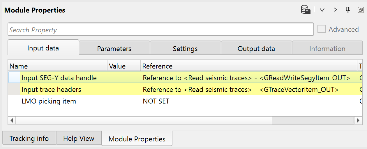
Parameters:
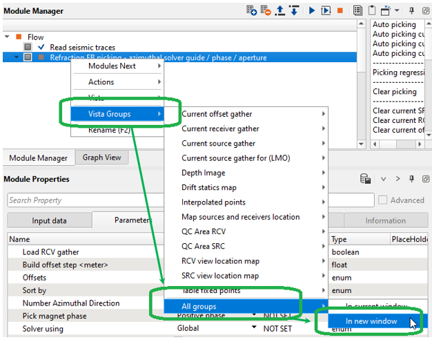
Further step is setting up user work area, it means making configuration of all necessary Vista Windows for QC and interactive engagement. Click RMB on the module and open all Vista Groups:
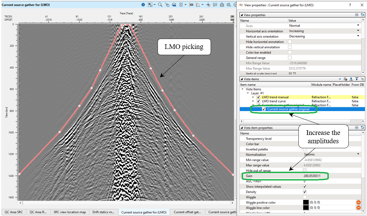
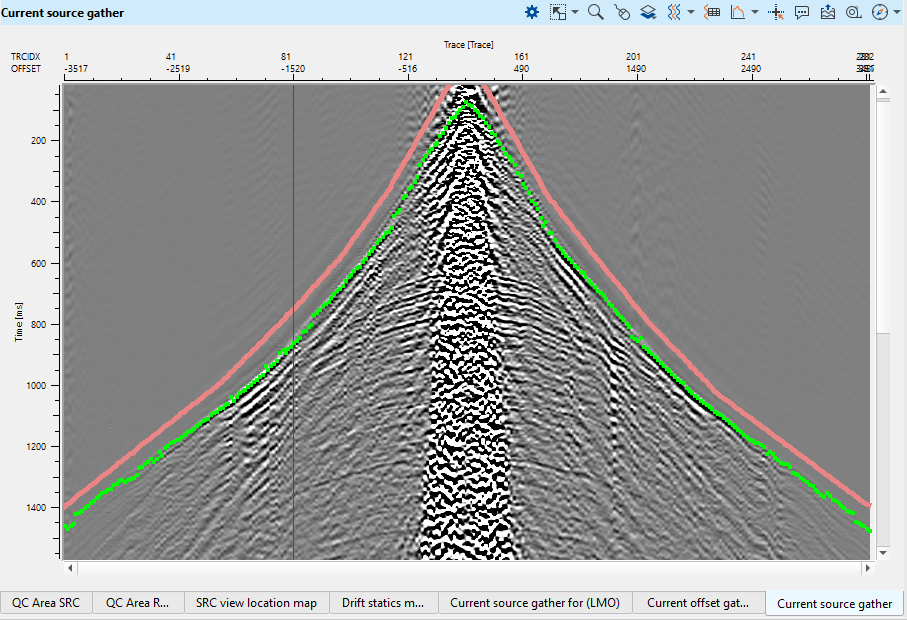
On the first Vista Window, there is a Linear Move Out (LMO) picking on source gather. The LMO is one of the main parameters for FB picking, in view of the fact that it is used as a guide function for auto FB picking. Consequently, we should pick LMO guide function on a few source gathers for different locations through the acquisition area. Picking may be located exactly on the first arrivals or a little bit above them, it depends on what option (algorithm) and parameters you use for auto picking. For the training data it is enough to make LMO picking only for one source due to the fact the there is a flat relief.
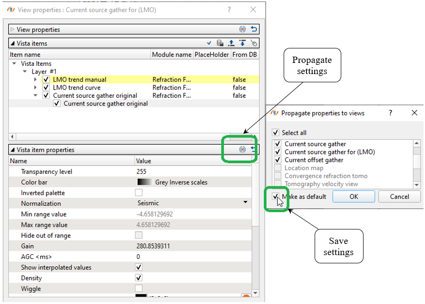
All the visual setting were configured and we can propagate and save them as default:
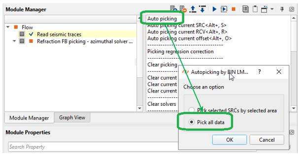
Next, open the source gather FB picking window and execute one source FB picking by pressing Auto picking current SRC<Alt+,S> button:
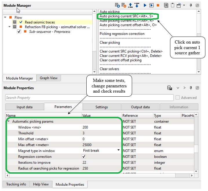
Then we are going to launch auto picking for the entire data set by clicking on Auto picking action button:
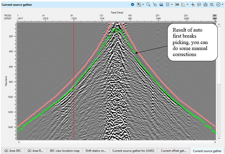
Check the result, it is obvious that picks became more accurate because the algorithm uses neighbor gathers for statistics:
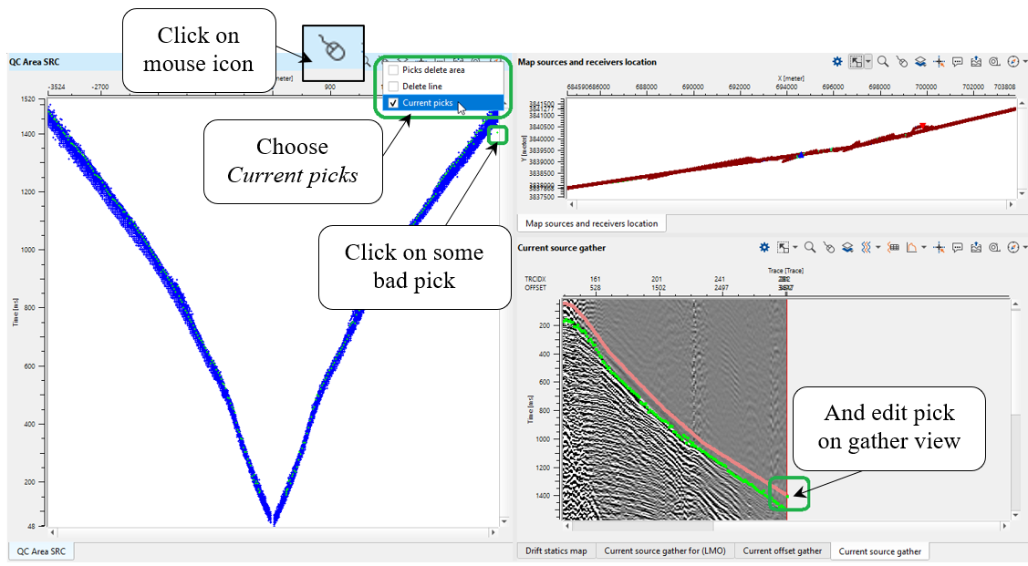
Eventually we have all FB picks and need to check it, open the Map sources and receiver location and activate Selected source option:
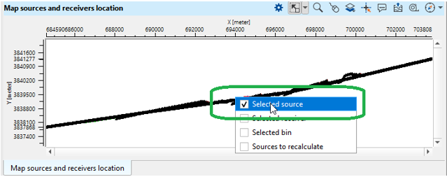
Now we can choose any source from the location map and perform FB picks QC and editing. Other windows are connected to each other automatically, so it allows to perform interactive QC on fly:
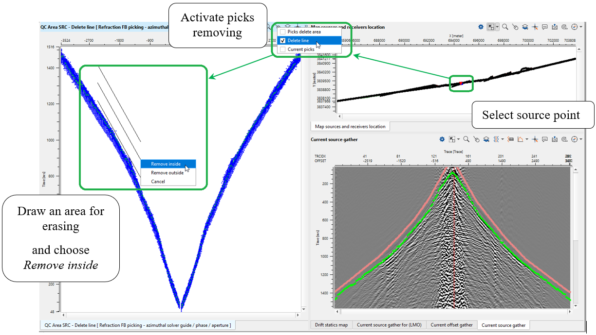
Or choose another option for picks removing:
There are other QC windows available from the Refraction FB picking - azimuthal solver guide / phase / aperture module.
The final step is export FB picking to binary file that we will use for tomography process. Find Export picking action and choose Save in Binary, because tomo statics module requires binary format:
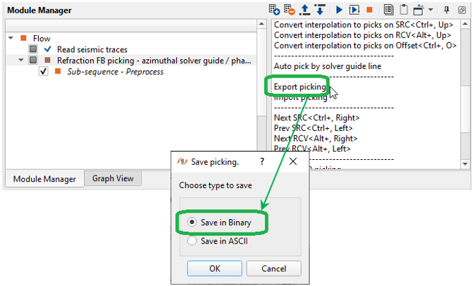
Define a name of the output binary file FBpick, we will use this file in the next step - tomography.
Now we have all FB picks and there two options for static calculation, by using the following modules:
• Refraction FB picking – azimuthal solver guide / phase / aperture;
•Tomo statics 2D.
Execute Refraction FB picking – azimuthal solver guide / phase / aperture, now we have refraction static correction and it is easy to do a QC. Go to vista window Current source gather and do a quick statics QC:
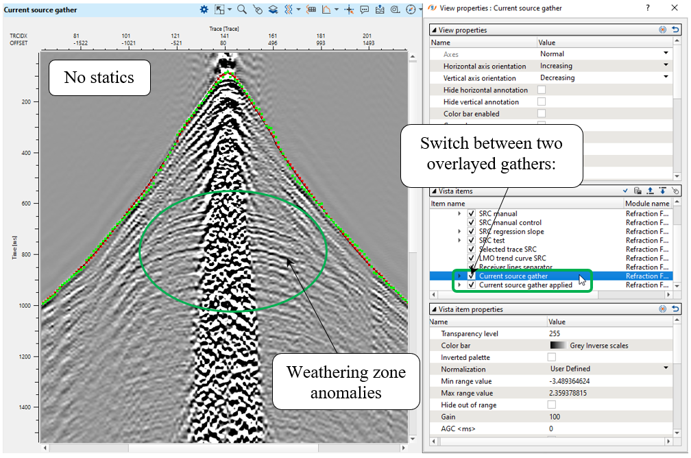
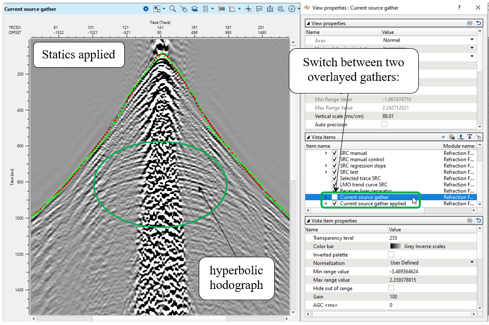
It was a fast QC of static corrections calculated by Refraction FB picking – azimuthal solver guide / phase / aperture.