Velocity picking, Mute picking, Stack creation
![]()
![]()
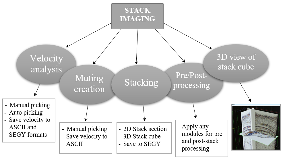
Velocity analysis [auto + manual] and stacking
Stack imaging module is a complex interactive application for stacking velocity analysis, creating mute function, stacking CMP gathers and pre/post processing sequence inside. We can create 3D stack cube and visualize it in 3D view mode, We can get a fast-stack for quick QC, we can create velocity picks and save them into ASCII file or internal DB, we can import legacy velocity field and build a stack section and so on, everything that is about velocity and stacks. Pay attention that migration velocity analysis performs by other modules: Velocity Selector - Kirchhoff PreSTM Engine - migration CIG panels creation, PSTM imaging selector 2D (velocity/angle/offset) - velocity picking.
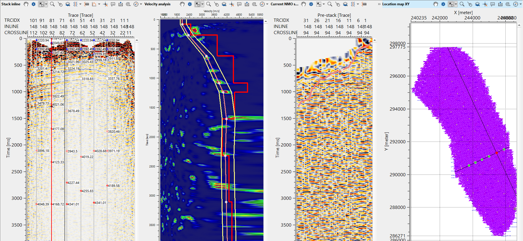
Input data is gathers in any sorting, without NMO corrections.
![]()
![]()
Input DataItem - Make a reference to the Read seismic traces or any other module which has prestack seismic data as an input. This is the only mandatory reference input data requirement for Stack Imaging. Other input data items are optional.
Input SEG-Y data handle - Connect/reference to Output SEG-Y data handle of Read seismic traces module or similar module.
Input bin grid - this is not mandatory however if the user connect/reference to the Output DataItem then it automatically gets all the trace headers and bin headers information from it.
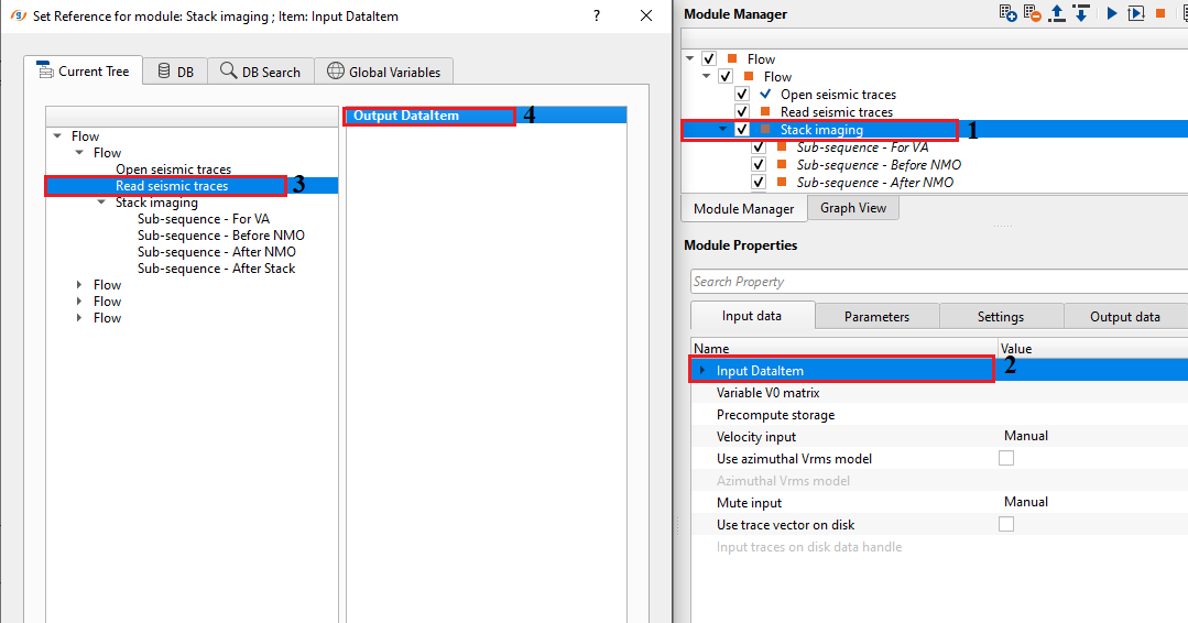
Variable V0 matrix - In case the replacement/near surface velocity V0 is variable then the user should provide the velocity matrix as an input. Accordingly, we should check the option in Velocity Analysis parameters.
Precompute storage - Provide a storage name for precomupting the velocities. Use in case of large surveys.
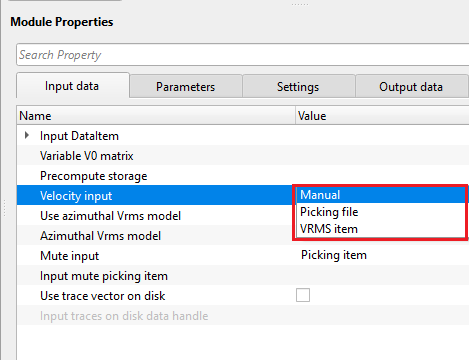
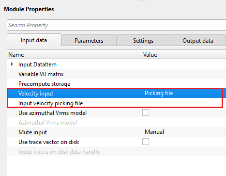
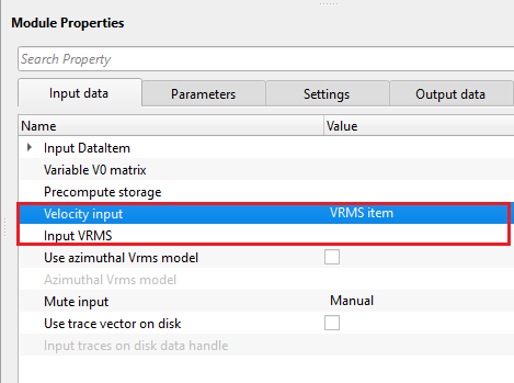
Velocity input { Manual, Picking file, VRMS item } - This options allows the user to select different options to input the velocity files. Based on the user selected option, it provides the parameters. By default, Manual.
Velocity input - Picking file - If the Velocity input type is selected as Picking file then provide the input velocity picking file.
Input velocity picking file - provide the input velocity picking file.
Velocity input - VRMS item - connect/reference to the Input VRMS as an item.
Input VRMS - Provide the Input VRMS in case we have an external velocity model or using a velocity model as an input gather. In case we provide the input VRMS then the we should change the Velocity usage option in the Parameters accordingly.
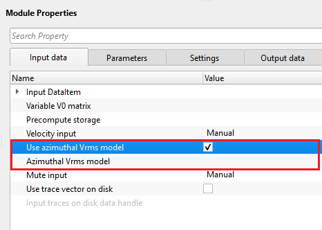
Use azimuthal Vrms model - this section deals with azimuthal Vrms velocity model. By default, FALSE (Unchecked).
Use azimuthal Vrms model - true - If this options is TRUE (Checked), provide the input Azimuthal Vrms model
Azimuthal Vrms model - connect/reference to the input Azimuthal Vrms model.
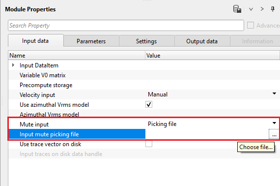
Mute input { Manual, Picking file, Picking item } - this section deals with the muting. As per the available options from the drop down menu, the user should provide the appropriate files. By default, Manual.
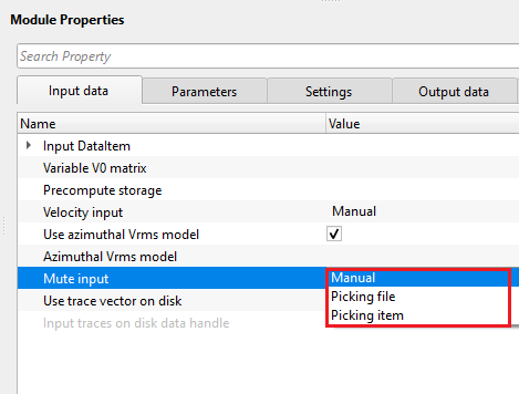
Mute input - Picking file - if the input mute type is selected as Picking file then provide the input file
Input mute picking file - choose the input mute picking file.
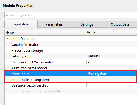
Mute input - Picking item - If the input mute type is selected as Picking item, then provide the input mute picking item.
Input mute picking item - connect/reference to any mute picking module and using mute function in the current module.
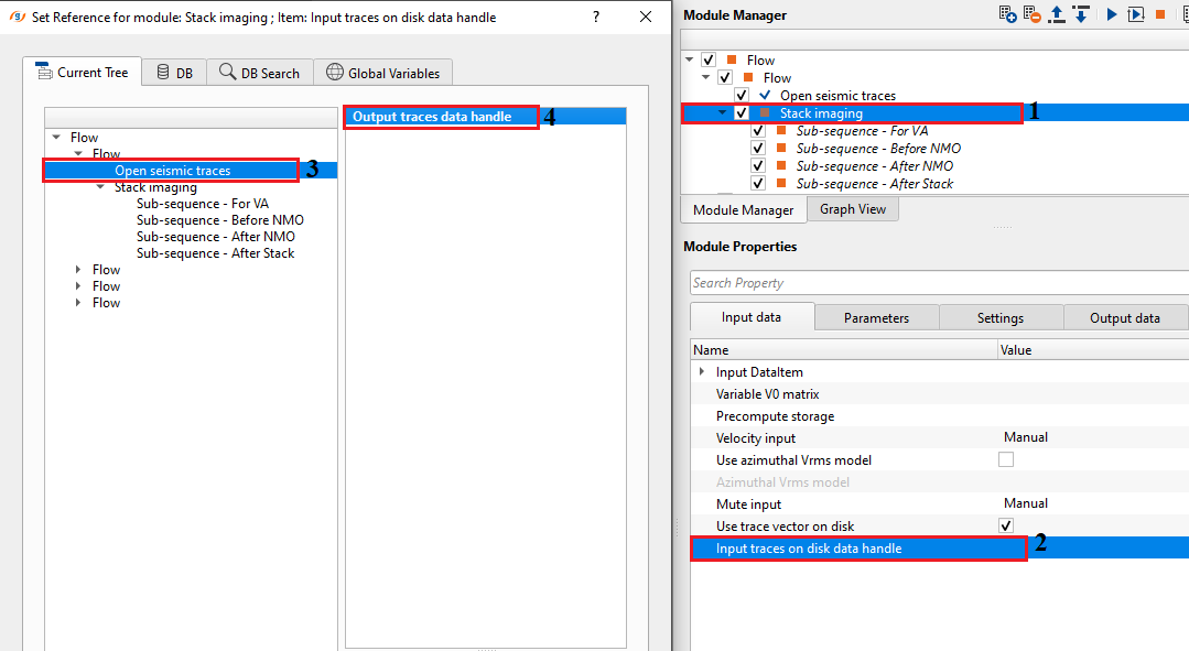
Use trace vector on disk - this option is applicable when the input data size is big and needs to be read by Open seismic traces module. By default, it is FALSE (Unchecked). If it is TRUE (Checked), the user should connect/reference Output traces to disk data handle.
Use trace vector on disk - true - By default, FALSE (Unchecked). If TRUE (Checked), provide the Input traces on disk data handle.
Input traces on disk data handle - connect/reference to Output traces data handle of "Open seismic traces" module.
![]()
![]()
Pay attention on what is inside Stack imaging module, it is sub-sequence. Sub-sequence helps to avoid creating a separate workflow to apply an AGC or Deconvolution or other processing modules, we just simply insert those modules in the sub-sequence inside the main module. Put modules inside the sub-sequence as shown below:
•Sub-sequence - For VA: processing for velocity analysis, i.e. apply some procedures like band-pass or AGC, and then velocity spectrum is calculated;
•Sub-sequence - Before NMO: processing before applying NMO corrections to gathers, for example we can apply static corrections;
•Sub-sequence - After NMO: processing before applying NMO corrections to gathers, for example we can apply denoise procedures;
•Sub-sequence - After Stack: processing after stacking CMP gathers, for example we can apply denoise procedures or spectrum balancing.

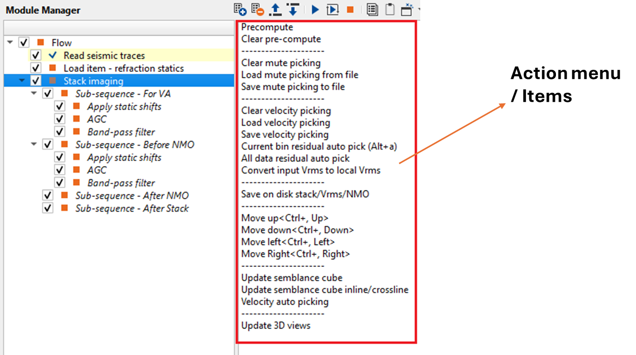
If we look at the action items menu on the right hand side of the Stack Imaging module, there are many options like loading, saving and clear libraries (velocity, mutes), auto-picking mode and other. Of course some functions are optional and we don't need to use all of them, but some of them are often used:
There are a lot of parameters in this module, but most of them we can keep as default. Read parameters definition below just for common understanding:
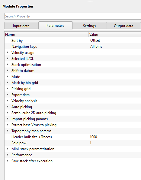
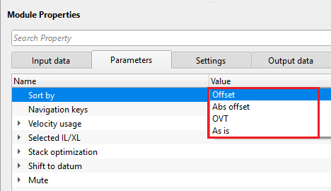
Sort by { Offset, Abs offset, OVT, As is } - This parameter defines how to sort the input data. Default: by offset. Upon expanding the menu, we have few options:
Offset - This option sorts the data in offset domain.
Absolute Offset - This sorting method considers the absolute offset.
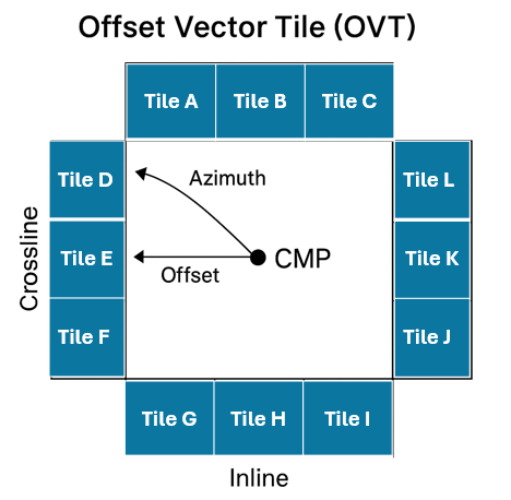
OVT - Offset Vector Tile. It sorts the data based on Offset & Azimuth. Due to this, all the bins (CMP/CDP) are having the similar offset and azimuth are grouped together.
As is - It sorts the data as per the input data.
Navigation keys { Net, All bins } - It determines how the user wants to navigate inside Stack Imaging to pick velocities or mutes. Here we have two options:
Net - If the user selects this option, the user have the limited ability to navigate through the data i.e., the user can go to a particular defined point only.
All bins - This option allows the user to navigate through all the bins that are available. It means, the user can select any random location( in this case bin) and pick either the velocities or mute.
Velocity usage: - It determines what kind of velocity we can use:
Consider only picks on current line - By default, it is unchecked. If checked, it will consider consider the velocity picks only to that particular inline/xline and update the stack accordingly.
Use External VRMS - In case the user have the velocity information in an external format like SEGY, then we can use this option to consider the external velocity information in stack creation. If the user chooses this option, they must provide the Input VRMS at the Input data tab.
Use pickets - The velocities are interpolated along the stack line/crooked line. Otherwise, the velocities are interpolated using X, Y coordinates.
Interpolation type { Kriging, Triangulation } - there are different interpolation methods available to interpolate the velocities. Select the desired interpolation method from the drop down menu.
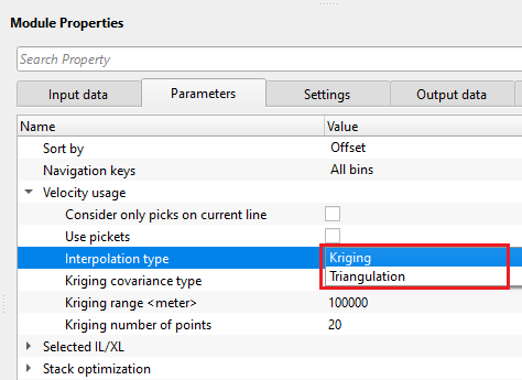
Kriging is a statistical interpolation method based on the assumption that the spatial data points are correlated. It creates an optimal surface that minimizes prediction errors by considering both the distance between data points and their spatial correlation.
Triangulation creates network of triangle from a set of data points. One of the commonly used triangulation method for interpolation is Delaunay. It ensures that no data point is inside the circumcircle of any triangle in the mesh. This produces a set of non-overlapping triangles where every point lies on the edge of one of these triangles. A linear interpolation will take place where the value at any point inside a triangle is estimated by taking a weighted average of the three vertices of the triangle.
Kriging covariance type { Exponential, Spherical, Gaussian } - Choose the covariance type from the drop down menu.
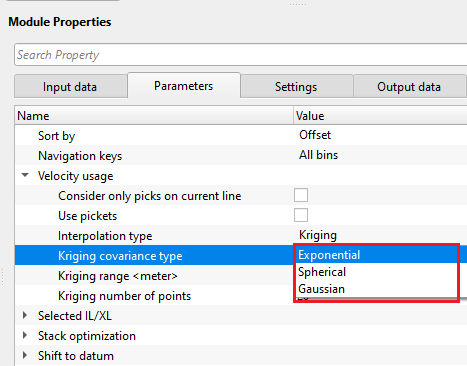
Exponential - This can be used where the subsurface properties change abruptly over small distances.
Spherical - The Spherical model is useful when the data exhibits a more gradual spatial correlation up to a certain range and then behaves independently beyond that range. When subsurface structures have coherent properties within a certain distance but lose coherence at greater distances.
Gaussian - The Gaussian model is often applied in cases where there is a long-range, gradual spatial dependence between data points. It’s suitable for data where the spatial dependence does not drop off abruptly, such as when seismic properties gradually change over larger distances or in homogenous subsurface areas.
Kriging range - If two data points are closer than the kriging range, they are considered spatially correlated and will influence each other's estimated values. If the distance is greater than the range, their influence on each other will be ignored. If the distance between two data points is more than 500 then it assumes that the data beyond that limit there is no correlation.
Kriging number of points - Total number of data points used to estimate/interpolate the unknown point/sample. The more the kriging points the better result however the computation time also increase with this.
Selected IL/XL: - Here we can define or choose a specific inline/xline.
Selected inline - Specify the inline number which needs to be created
Selected crossline - Specify the crossline number to be created and/or pick velocities. In case of 2D data, it will be crossline.
Stack Optimization: - Inside this, we can determines how to optimize the stack:
Value threshold - By default it calculates from the input data and the user doesn't need to provide anything here. Ignore this parameter.
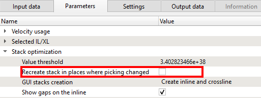
Recreate stack in places where picking changed - It will ONLY creates the stack where the velocity picks were changed/edited. Rest of the stack will remain the same.
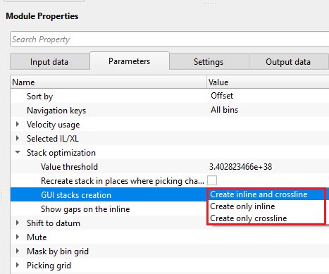
GUI stacks creation { Create inline and crossline, Create only inline, Create only crossline } - We can choose whether we want to generate only an inline or crossline or both.
Show gaps on the inline - By default, it is checked. If there are any data gaps in inline/crosslines it will display them.
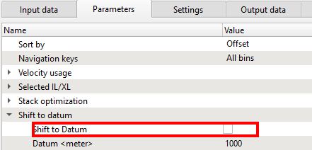
Shift to datum: - We can shift the data to final datum or keep it as it is (at topography). As we mentioned earlier, in g-Platform, we estimate velocities from the topography level. In Binning 2D module, we provided created a smoothing topography which is representation of the floating datum. Here we are smoothing the CMP elevations only. The source and receiver elevations remain same:
Shift to Datum - By default, FALSE (Unchecked). If user would like to shift the data to datum then we need to check this option and provide Datum value.
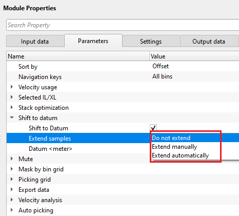
Extend samples { Do not extend, Extend manually, Extend automatically } - it extends the output data length. Choose the available options from the drop down menu.
Do not extend - it won't extend the input data length.
Extend manually - it extends the input data length as per the user defined value.
Extend automatically - it will extend the data as per the user specified datum value.
Extend samples - Extend manually - this option is applicable when the user specified the extend samples as Manually. In this case, the user should provide the final input data length.
Output data length - specify the final input data length. By default, 4000 ms.
Datum(meter) - If the previous option is checked, then we should provide the Datum value to shift the data from current datum to the final datum.
Mute: - This parameter determines the mute taper value in case we have mute function.
Taper window (ms) - Tapering between muted and saved zones to avoid any sharp boundaries or creating any edge effects.
Use mute for semblance gather - by default, FALSE (Unchecked). If TRUE(Checked), it will apply the mute for the semblance also. Based on the mute, semblance response changes.
Update semblance on mute click - by default, TRUE (Checked). This will update the semblance response/display.
Mute apply mode { Auto, Manual } - select the mute application type from the drop down menu. By default, Auto.
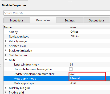
Mute apply mode - Manual - In case the mute application type is selected as Manual, there are additional parameters applicable to choose the type of mute to apply.
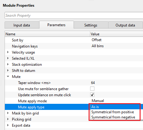
Mute apply type { As is, Symmetrical from positive, Symmetrical from negative } - this is applicable when the mute type is selected as Manual.
As is - as per the current mute type.
Symmetrical from positive - applies the mute symmetrically from the positive offset.
Symmetrical from negative - applies the mute symmetrically from the negative offset.
Mask by bin grid: - This is helpful in case of 3D to crop some of the minimum and maximum offsets while creating the inline/crosslines or the volume.
Min offset mask apply - If checked, define the minimum offset for all the CMPs to crop them, means it won't be used in the final stack.
Max offset mask apply - By default, unchecked. It is similar to the Min offset mask. If checked, define the maximum offset to crop.
Smooth - Smoothing value.
Picking grid: - We can define at what interval we should pick the velocities. In case of 2D, if we want to pick the velocities at 2 km interval and the CMP interval is 12.5 m then we need provide 160 (2000/12.5 = 160) as inline/cdp increment value or step size.
Inline/CDP increment - Provide the inline increment step size. In case of 2D, provide the CDP increment step size as explained above.
Crossline increment - Provide the crossline increment step size.
Export data: - This parameter is purely reading the data while exporting the data.
Read bins bulk size(Bins) - Define the number of bins to read in a bulk. By default 200.
Velocity analysis: - This is the main component of creating the semblance display. Inside the Velocity analysis, the user should define various parameters to generate the semblance, Common Offset (CO) gather, NMO stretch factor etc.
Use variable V0(matrix) - In case the near surface/replacement velocity is varying and not constant the user can check this option to consider Variable V0. If this option is checked, the user must provide the Variable V0 matrix at the Input data tab.
Replacement velocity (m/s) - Specify the replacement or near surface velocity value for datum shift.Set this value prior to beginning of the velocity picking.
Start velocity (m/s) - Define the starting velocity value for creating the semblance.
Ending velocity (m/s) - Define the ending velocity value for creating the semblance.
Velocity increment (m/s) - Specify the the velocity increment step size. By default 50 m/s.
Semblance smoothing window (ms) - This value defines the smoothing of the semblance display. Higher window makes the semblance more smooth which is not ideal an ideal scenario but it depends on the input data quality. Default parameter value of 50ms works good.
Stretch factor (%) - This parameter determines the NMO stretch factor. By default 50. If the user changes this value then the user can to observe the changes in the Velocity analysis window (Semblance display), Current NMO Seismogram display. Once the user executes the Stack Imaging module with the updated Stretch factor then the stack will be created using user defined NMO stretch factor.
Smoothing parameter Y velocity (Samples) - Default value is 10. Define the number of vertical samples to define the velocity smoothing.
Normalization window (ms) - Default 100 ms. This parameter is used for normalization of the semblance display.
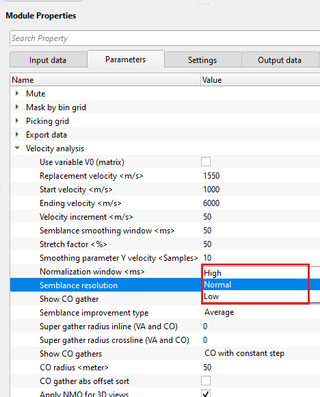
Semblance resolution { High, Normal, Low } - Select the type of resolution. We have 3 options, Normal (By default), Low and High. By meaning of the Low and High, it decreases/increases the semblance resolution. Depending upon the input data quality the user can select the appropriate semblance resolution.
Show CO gather - By default unchecked. If the user wants to display the Common Offset (CO) gather then check this option.
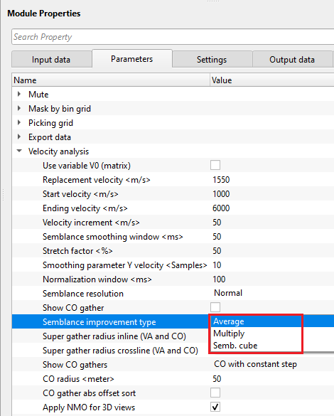
Semblance improvement type { Average, Multiply, Semb. cube } - By default Average. Select the appropriate type from the available options to adjust the semblance calculation to improve the semblance display.
Super gather radius inline (VA and CO) - Define the super gather radius in inline direction
Super gather radius crossline (VA and CO) - Define the super gather radius in crossline direction
Show CO gathers { CO with constant step, CO with original geometry } - If this option is checked, it will display the Common Offset gathers with different options.
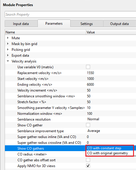
CO with constant step - Displays the CO gathers with a constant CO offset step size. The step size should be defined at CO radius (meter).
CO with original geometry - It will display the CO gathers at original geometry.
CO radius (meter) - Define the Common Offset step size.
CO gather abs offset sort - By default unchecked. If checked, it will sort the CO gathers in absolute offset.
Auto picking: - This part of Stack Imaging module provides auto picking. We should provide the following parameters.
Use semiautomatic picking - by default it is unchecked. If it is checked, it will adjust the user picked velocities to the maximum semblance value.
Min velocity deviation (%) - percentage of minimum velocity deviation from the input 100% velocity.
Max velocity deviation (%) - percentage of maximum velocity deviation from the input 100% velocity.
Max time deviation (ms) - maximum acceptable time deviation. It's time window for single auto-picking.
Inline/cdp start autopick - starting inline (in case of 3D) or CDP (in case of 2D) number for auto-picking.
Crossline start autopick - starting crossline number to auto-picking.
Inline/cdp step autopick - this parameter is for residual auto picks only. Provide the inline/CDP step size.
Crossline step autopick - crossline step size for residual auto pick.
Detect points sensitivity - spectrum sensitivity for auto-picking.
Semblance threshold - when semblance calculation is done, it is either 1 or 0. If the correlation between any two given points is 1 then we have a very good semblance otherwise we have no semblance which means 0. In the case of automatic velocity picking, when the user provides a semblance threshold value of 0.5, then it will ignore picking the velocities anything below 0.5 semblance threshold.
Semb. Cube 2D auto picking: - This is used for auto picking the velocities based on velocity corridor.
Inline/CDP step autopick - This is the main parameter at what interval the automatic velocity picking should be done. If user provides the Inline/CDP auto-picking step a= 25, then it will automatically pick the velocities at every 25-th Inline/CDP.
Aperture - Number of neighboring BINs to analyze the semblance for the current picking location.
Slope (%) - This parameter relates to the reflectors. If the reflectors are straight then the slope can be less otherwise the slope can be a higher value.
Multiplied super gather radius inline - It is number of bins used to analyze the semblance and multiplied by the user defined factor. Higher multiplication factor means less events for auto picking. The higher multiplication factor stabilizes the semblance laterally.
Time smoothing window (ms) - Provide the smoothing window smoothing velocity function. The larger smoothing window the smoother velocity function.
Time step (ms) - Provide the time step at what interval the automatic picking should take place.
Corridor width (m/s) - Define the velocity corridor width.
Magnet picking points to geometry - By default, it is checked. The main objective of this parameter is to detect or select the exact Inline/CDP/Cross line location in the location map or location map inline/crossline. In case the user picks somewhere on the location map but not exactly at the desired position, based on the Magnet max distance - it will automatically search and select that position on the location map.
Magnet max dist (meter) - Define the magnet maximum distance to search for the point.
Extract base Vrms to picking : - This parameter is directly related to Input VRMS in Input data tab. When the user reads the external velocity or internal velocity by gather, it will extract the information based on the following parameter values.
Geometry step (meter) - Provide the geometry step size to convert/extract the input Vrms into internal velocity format.
Detect points sensitivity - Velocity point sensitivity.
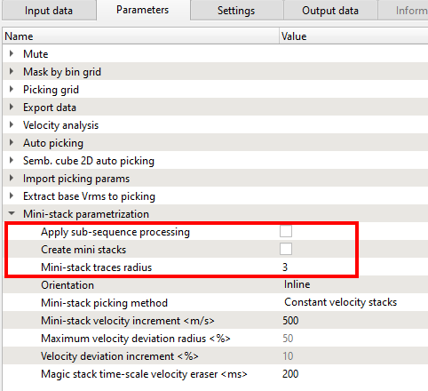
Mini-stack parametrization: Mini-stacks are also knows as CVS (Common Velocity Stacks). These are very useful in helping the user to get an idea about the overall velocity range and it's trend. There are few parameters needs to be filled to create these Mini-stacks in g-Platform. By default, the Mini-stacks display is not available in Vista Groups-> 2D groups or 3D groups. The user must separately add them.
Apply sub-sequence processing - By default unchecked. If checked, it will automatically apply the sub-sequence processing steps involved in VA/Before NMO.
Create mini stacks - By default unchecked. In order to create the Mini-stacks, the user must check this option to generate the Mini-stacks.
Mini-stack traces radius - Define the number of traces (CMPs) are considered in creation of the Mini-stacks.
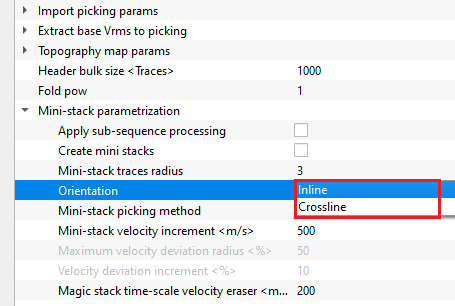
Orientation { Inline, Crossline } - Choose the Mini-stack orientation. By default, Inline. We can choose inline or crossline from the drop down menu.
Mini-stack picking method { Constant velocity stacks, Current interpolated velocity } - When we want to pick the velocities on Mini-stacks, the user have two options to choose from.
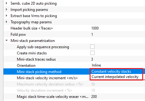
Constant velocity stacks - By default, this is the option wherein the stacks were created using a constant velocity defined by user at Velocity analysis parametrization.
Current interpolated stacks - We can to pick the velocities on interpolated stacks.
Mini-stack velocity increment (m/s) - Provide the velocity increment. From one Mini-stack panel to another Mini-stack panel, the velocity varies from the user defined value. This option is active when the Mini-stack picking method is Constant velocity stacks.
Maximum velocity deviation radius (%) - Define the maximum velocity deviation. This option is active when the Mini-stack picking method is Current interpolated stacks.
Velocity deviation increment (%) - Percentage of minimum velocity deviation from .
Magic stack time-scale velocity eraser (ms) - Interactive velocity eraser.
Topography map params - this section deals with the topography map creation parameters.
Map interpolation step - By default, 100 meters. Specify the interpolation step for creating the topography map.
ABOS grid distance X - ABOS is one kind of interpolation method. It is a interpolation method to fill in missing topography information. Specify the grid distance in X direction.
ABOS grid distance Y - specify the grid distance/size in Y direction for performing interpolation in Y-Direction.
Header bulk size - By default, 1000. It reads 1000 traces as a single bulk.
Fold pow - By default, 1. Fold power is a stacking weight function that uses number of contribution traces as an exponent to enhance or control the influence of stacking.
Fold power = 1; means normal stacking where all the folds are considered
Fold power > 1; means higher fold areas are down weighted
Fold power < 1; means higher fold areas are emphasized.
Performance - this section deals with the 3D views.
Update 3D views - By default, FALSE (Unchecked). This option allows the user to update the 3D views like inline, crossline and time slices.
Save stack after execution - this section deals with saving of the stacks after execution. The output can be used as a standard SEG-Y output file or internal GSD file. Also, these output files are used for "Progressive Stack" module as input files. Progressive stack requires multiple input GSD/SEGY files to prepare a single file. This single will be used as a volume to visualize it by using "Visualization 3D volume" module.
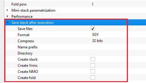
Save files - it allows the user to save the files. By default, FALSE (Unchecked). If TRUE(Checked), other options are enabled and provide the parameters accordingly.
Format { SGY, GSD } - select the output file save format from the drop down menu. By default, SGY.
SGY - Standard SEG-Y format
GSD - Geomage Standard Data (GSD) format which is an internal format.
Compress { 32 bits, 16 bits, 8 bits } - this option allows the user to reduce the size of the output file by compressing the output. Select the compressing type from the drop down menu. By default, 32 bits.
Name prefix - provide the output file name
Directory - provide the output directory name.
Create stack - this option creates stack. For Progressive stack, it requires both Create Stack & Create Fold.
Create Vrms - it creates Vrms velocity
Create NMO - it creates NMO gathers
Create fold - it creates fold map. For Progressive stack, it requires both Create Stack & Create Fold.
![]() Velocity picking within the Stack Imaging module is not corrected to final datum. In g-Platform, we pick velocities on the topography and shift it to the final datum if necessary. In that case, we should use Shift to datum option inside the Parameters tab. Also we can perform this task by adding the Shift to datum module under the Sub-sequence - After stack. The velocities are still at Topography. Only the stack shifted to Final datum.
Velocity picking within the Stack Imaging module is not corrected to final datum. In g-Platform, we pick velocities on the topography and shift it to the final datum if necessary. In that case, we should use Shift to datum option inside the Parameters tab. Also we can perform this task by adding the Shift to datum module under the Sub-sequence - After stack. The velocities are still at Topography. Only the stack shifted to Final datum.
![]() During NMO application, the source and receiver elevation statics are calculated automatically by shifting to CMP (Bin) elevation, and applied to the seismic trace.
During NMO application, the source and receiver elevation statics are calculated automatically by shifting to CMP (Bin) elevation, and applied to the seismic trace.
![]()
![]()
Auto-connection - By default, TRUE(Checked).It will automatically connects to the next module. To avoid auto-connect, the user should uncheck this option.
SegyCacheParams
SegyReadParams - parameters for setting advanced parameters of reading seismic traces from disk
Thread count (for SSD) - amount of treads for reading seismic traces from disk.
Bulk size (traces) - size of a chunk (data portion) for reading seismic traces from disk.
Number of threads - One less than total no of nodes/threads to execute a job in multi-thread mode. Limit number of threads on main machine.
Skip - By default, FALSE(Unchecked). This option helps to bypass the module from the workflow.
![]()
![]()
Full stack out - generates full stack as an output.
Output mute picking item - generates output picking mute item.
Output velocity picking - generates output velocity as an item.
Output velocity picking corridor - generates velocity picking corridor as a vista item.
Selected seismogram - generates selected seismogram as a vista item.
Selected seismogram NMO - generates selected NMO seismogram as a vista item.
Selected seismogram CO - generates selected Common Offset (CO) seismogram as a vista item.
Selected seismogram NMO CO - generates selected NMO Common Offset (CO) seismogram as a vista item.
Magic stack inline - generates stack inline as a vista item.
Stack inline - generates inline stack as a vista item.
Stack crossline - generates crossline stack as a vista item.
VRMS inline - generates Inline VRMS as a vista item.
VRMS crossline - generates Crossline VRMS as a vista item.
Output gather mini-stacks - generates min-stacks as a vista item.
There is no information available for this module so the user can ignore it.
![]()
![]()
In this example workflow, we discuss various topics of Stack Imaging. They include
•How to pick velocities manually?
•How to pick velocities automatically?
•How to pick velocity corridor?
•How to edit velocities?
•How to pick mute?
M A N U A L P I C K I N G
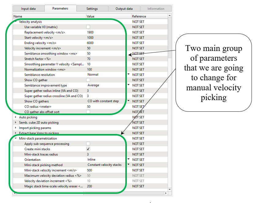
Look though the parameters that we are going to change for manual picking. Pay attention on super-gathers and mini-stacks: increase number of CMP gathers for semblance and turn on mini-stacks calculation:
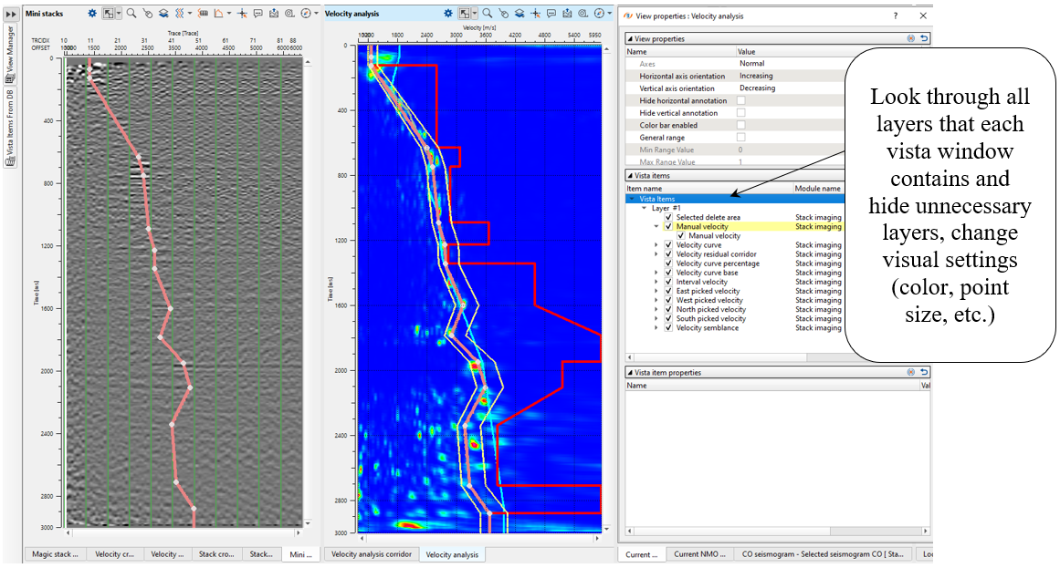
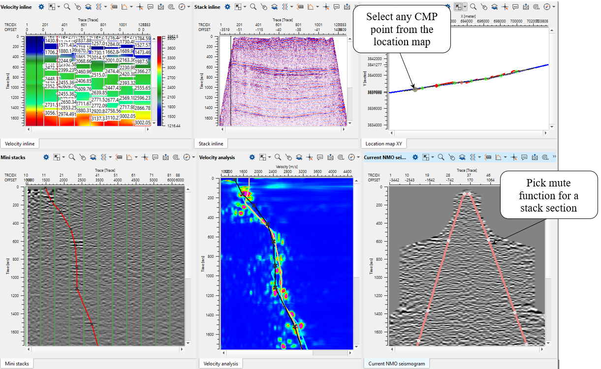
Open all vista groups and mini-stacks (do it manually, by default it is not in vista groups). Look at the picture below, you should have something similar, it is default visual setting and windows configuration. Make some changes of visual settings, open view properties of Velocity analysis and Mini-stacks: change layers visibility, colors, points size, etc.

Perform velocity picking on current CMP point: pick on semblance or mini-stacks section. To pick velocities, click on the velocity analysis window panel. It will come up with three lines. The two yellow lines are basically the Velocity corridor and the middle line is the Current velocity pick trend (input velocity 100%). Once we start picking the velocities, a red line appears which is the Interval velocity.
For removing any picks any bad picks: should hold RMB and draw a polygon. Whatever is falling inside the polygon will be removed.
For editing any picks: click on the area near a particular pick and it will be moved to a new position:

Configure all vista windows as you prefer and make velocity picking for several CMP points. You can remove some of the extra vista windows and use them if necessary. For example, there is a list of vista windows that we can use for current 2D velocity analysis: Velocity inline, Stack inline, Location map, Mini stacks, Velocity analysis, Current NMO seismogram. As we are picking more locations, Velocity inline keeps updating however we still can't see the Stack inline. To generate the Stack inline, we should execute the Stack Imaging module either by double clicking on Stack Imaging module or press the Execute module ![]() icon.
icon.
Depending on the user's parameters, we can pick the velocities either randomly by selecting on the location map or as per the picking grid which was defined in the Parameters tab. To move left, right, up & down, one can look at the action items menu and use the short cuts to move around.
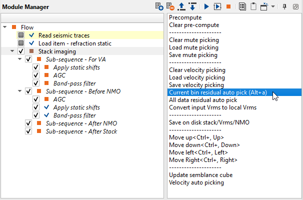
Since we have picked stacking velocity manually, there is an option for performing residual correction. For example, if some pick was picked inaccurate and should be corrected. Residual picking is NOT auto-picking mode. We will use another option for auto-picking in the further chapter. Go to the Action items (menu) and choose the option Current bin residual autopick for the current bin position only. Then use All data residual auto pick option for the entire data:
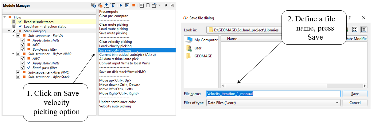
Press the Execute module ![]() icon again. Now we have a new stack, velocity and mute function for stack. But stack is on stack on floating datum (after NMO applying inside the module), but if we need to shift it to the final datum (constant) check the datum parameter. You can do this test with datums, compare two stacks: floating datum vs constant. Save final velocity on disk: use action menu-> Save velocity picking -> define a file name for velocity pick file:
icon again. Now we have a new stack, velocity and mute function for stack. But stack is on stack on floating datum (after NMO applying inside the module), but if we need to shift it to the final datum (constant) check the datum parameter. You can do this test with datums, compare two stacks: floating datum vs constant. Save final velocity on disk: use action menu-> Save velocity picking -> define a file name for velocity pick file:
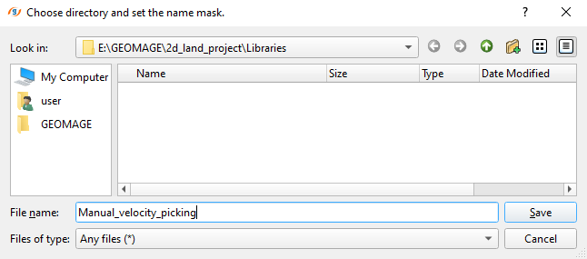
Optionally, we can save resulting stack, velocity and NMO gathers in SEGY format on a disk: choose the option Save on disk stack/Vrms/NMO from the action menu. Click on this option, a pop-up window opens with the default option as Save to SGY. Click OK. Now another pop-up window opens up with different options. There we can select one or all of them and click OK. Finally a file browser window opens and here we should provide a file name. Depending on the choice of our selection, it will suffix the names to the respective data type with an extension of SEGY to the data set.
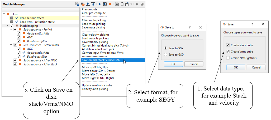
Write a mask name for output data and press Save:
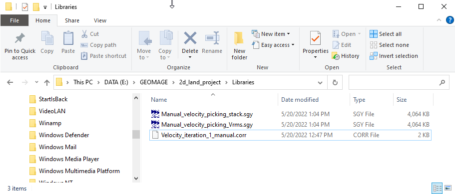
Check the folder and find output files:
A U T O P I C K I N G
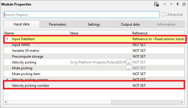
Velocity corridor is not required as an input at the beginning however when we execute Velocity auto picking option in Stack Imaging, it will give an error message that velocity picking corridor is required. To avoid that the user should first pick the velocity corridor. Connect Input DataItem and open all necessary vista groups. For example, you can use the following windows: Velocity analysis, Velocity analysis corridor, Location map XY, Current NMO seismogram, Stack inline, Velocity inline.
Input data:
Normally, when we open all Vista Groups, all visual windows appear, however Velocity analysis corridor is not part of the 2D groups. Therefore, we need to add the vista group Velocity analysis corridor separately as shown below:
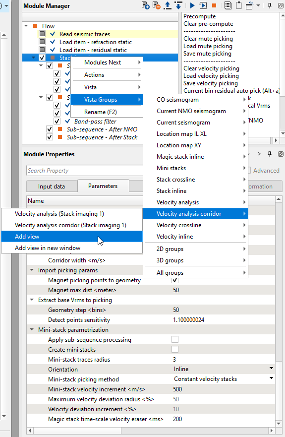
Now it will be added to the existing other Vista items. Velocity analysis and Velocity analysis corridor both look a like however the functioning of each one of them is slightly different. We use Velocity analysis for picking the velocity manually whereas in Velocity analysis corridor, we use it for picking the velocity corridor which is mandatory for picking the velocities automatically.
How to to pick the velocity corridor?
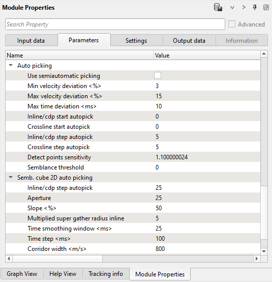
1. Define auto-picking and corridor semblance parameters. Open parameters tab of the module for automatic picking. As we discussed in previous chapter Velocity analysis (Iteration 1, manual picking), pay attention to the required parameters. In this chapter, we focus on two parameter sections Auto picking and Semb. cube 2D auto picking:
Parameters:
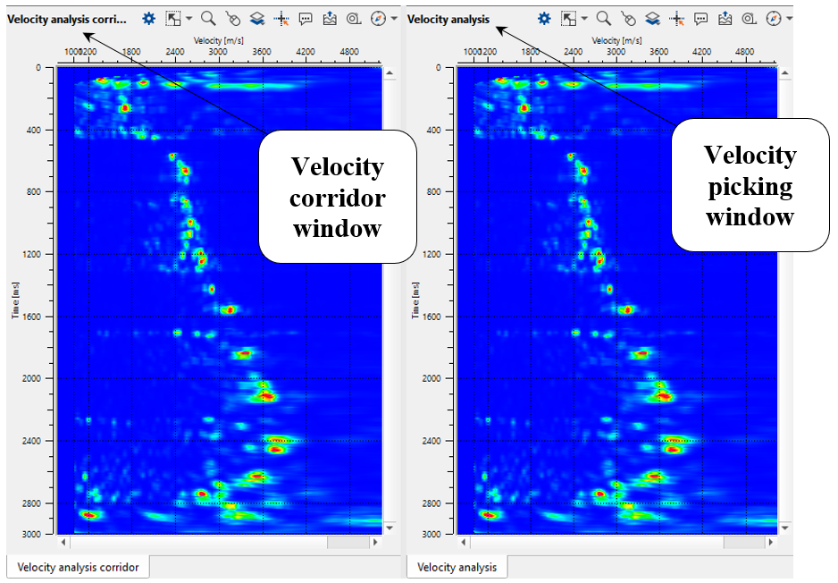
2. Click on any where on the Stack inline/Velocity inline or Location map and look at Velocity analysis window and Velocity analysis corridor:
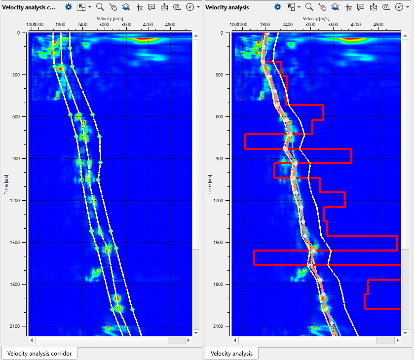
3. Next, go to the Velocity analysis corridor and choose Manual velocity corridor option from the control item ![]() icon. To pick the corridor, just click on the Velocity analysis corridor with MB1 or left mouse button. You will observe 3 lines, it is velocity corridor (left limit, center and right limit). To adjust the corridor picks, we can hold MB1 or LMB and drag the green points wherever we want. Pick velocity corridor by going through different CMP points and check. If the corridor is outside of the velocity semblance we can either pick a new velocity corridor at that particular CMP location or adjust the corridor. We need to pick a skeleton of velocity corridor for auto-picking. Corridor for each CMP point will be automatically interpolated between the two existing corridor picks.
icon. To pick the corridor, just click on the Velocity analysis corridor with MB1 or left mouse button. You will observe 3 lines, it is velocity corridor (left limit, center and right limit). To adjust the corridor picks, we can hold MB1 or LMB and drag the green points wherever we want. Pick velocity corridor by going through different CMP points and check. If the corridor is outside of the velocity semblance we can either pick a new velocity corridor at that particular CMP location or adjust the corridor. We need to pick a skeleton of velocity corridor for auto-picking. Corridor for each CMP point will be automatically interpolated between the two existing corridor picks.

Once we have picked velocity skeleton, now it is time for velocity auto picking. To do that, click on Velocity auto picking action item as shown below:

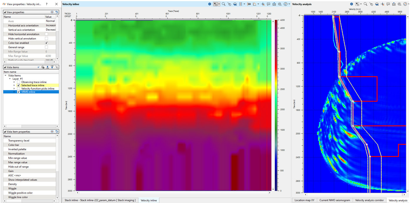
Velocity analysis corridor and Velocity analysis windows after auto-picking process:
Velocity model and Location map. Velocity is quite sharp, so we will apply smoothing and editing edge effects (caused by low fold):

Press the Execute module ![]() icon to rebuild a stack. Now we have a new stack, velocity and mute function for stack. But stack is on stack on floating datum (after NMO applying inside the module), but we need to shift it to the final datum (constant). Add Shift data module to the Sub-sequence - After Stack as shown below:
icon to rebuild a stack. Now we have a new stack, velocity and mute function for stack. But stack is on stack on floating datum (after NMO applying inside the module), but we need to shift it to the final datum (constant). Add Shift data module to the Sub-sequence - After Stack as shown below:
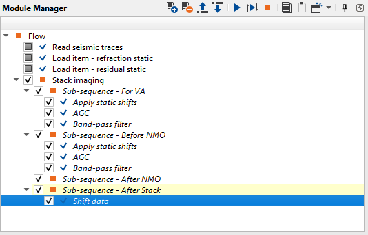
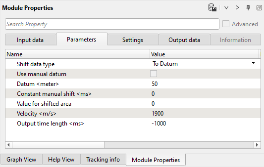
Define Shift data parameters:
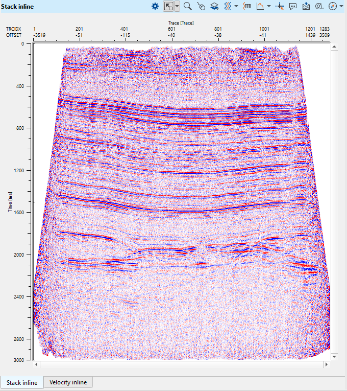
Press the Execute module ![]() icon to rebuild a stack on final constant datum plane:
icon to rebuild a stack on final constant datum plane:
.
Use datum parameter in Stack imaging module instead of using Shift data module inside the Sub-sequence - After Stack
Save final velocity on disk: use action menu-> Save velocity picking -> define a file name for velocity pick file:

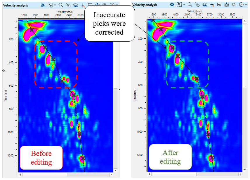
Velocity editing:
We need to correct edges, open velocity and spectrum windows. Go to the particular CMP point by clicking on picked CMP trace on the velocity stack section (Velocity inline), and correct or remove bad picks:
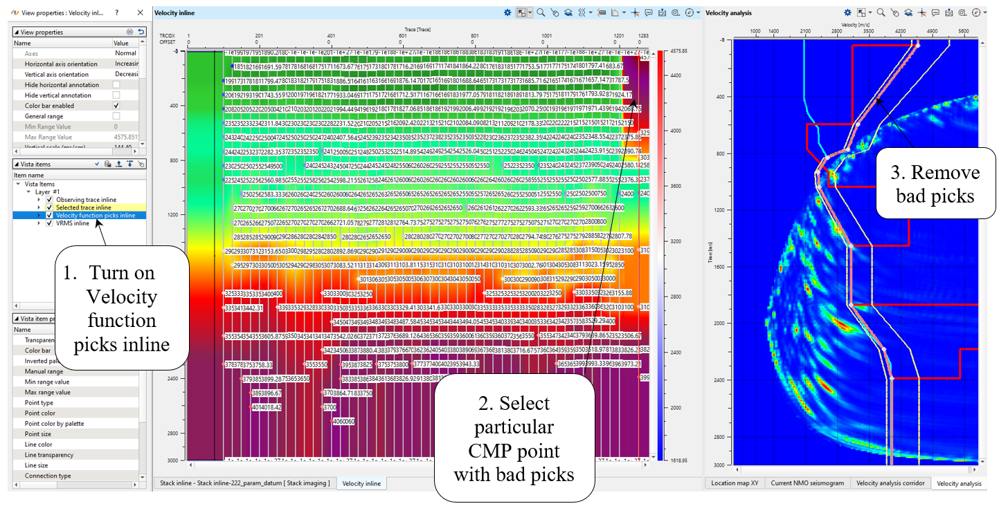
Now we don't have bad picks and need just smooth velocity model:
Add Smooth 2D module, define input data and parameters as shown below:
Input data:
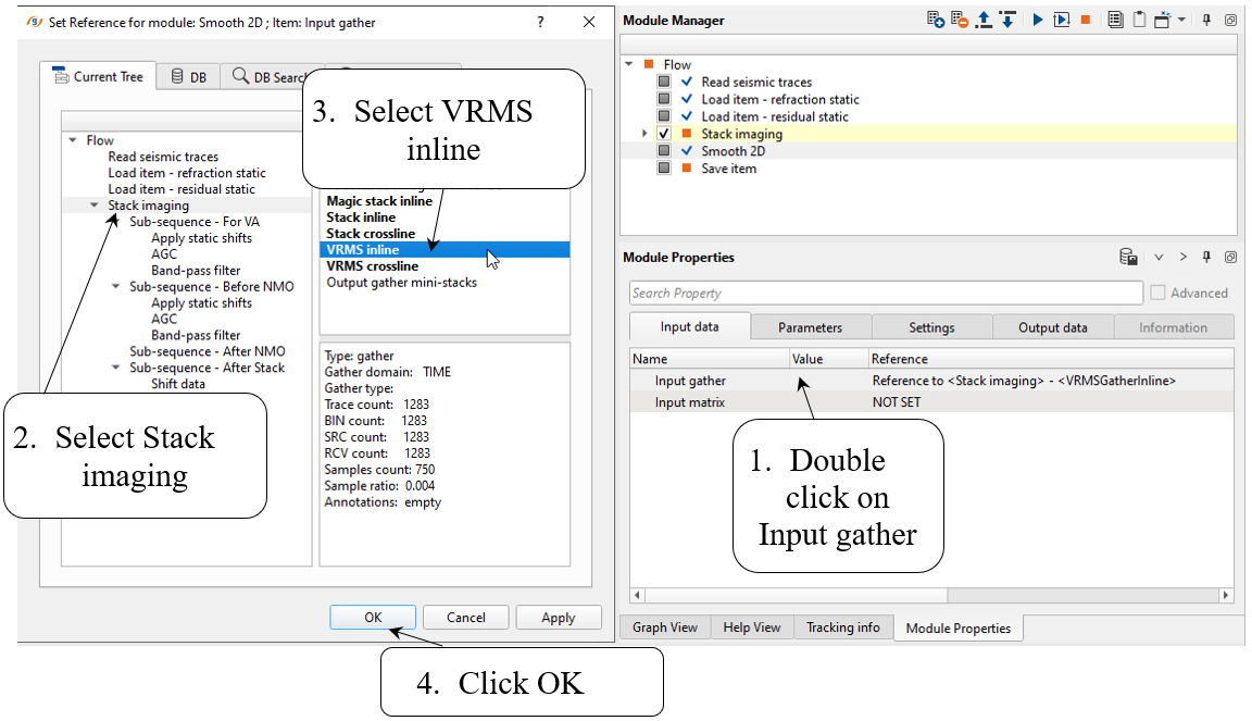
Parameters:

Execute Smooth 2D and open its vista views to check input and output velocity models:

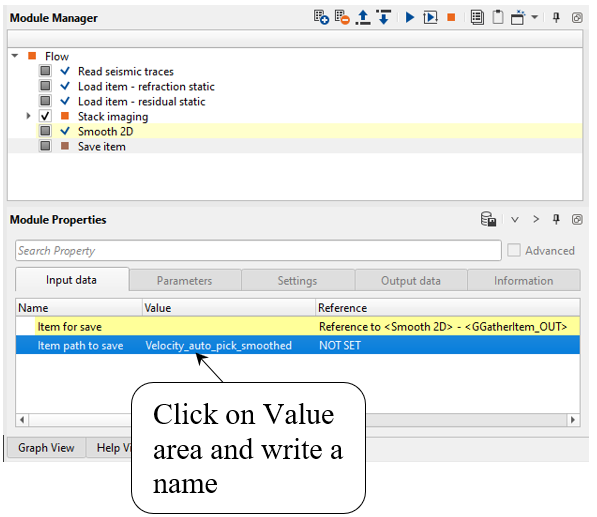
Add Save item module for saving velocity model into DB. Define input data and an output file name:
Input data:

Write a name for output velocity library Velocity_auto_pick_smoothed and execute the module:
We finished auto-picking velocity and saved result on the disk.
![]()
![]()
Precompute - this option allows the user to precompute the velocities as a single file. At the input data tab, the user should provide the precompute storage file name. It calculates the velocity semblance for the entire volume. It is useful whenever there is a big seismic volume.
Clear pre-compute - this options clears the pre-computation.
---------------------
Clear mute picking - it erases/clears the user picked mute or the user imported mute picking file.
Load mute picking - with this option, the user can import the picked mute file. This file will be displayed in the input data tab against "Mute picking"
Save mute picking - this option allows the user to save the picked mute. The output file saves with an extension of ".corr"
---------------------
Clear velocity picking - it clears/erases the user picked velocities or imported velocity file.
Load velocity picking - it allows the user to import the previously picked velocity file. This file is displayed in the Input data tab against "Velocity picking".
Save velocity picking - it allows the user to save the picked velocities. The output file will be saved with ".corr" extension.
Current bin residual auto pick (Alt+a) - it allows the user to pick the residual velocity of the current bin location.
All data residual auto pick - this option picks the residual velocities of the entire data.
Convert input Vrms to local Vrms - if the user provided the Input VRMS file to the Input data tab, it converts the file into Geomage g-Platform velocity file format.
---------------------
Save on disk stack/Vrms/NMO - this allows the user to save the Stacks/Velocities/Gather/Fold as a SEGY or GSD format file.
---------------------
Move up - allows the user to move one velocity picking location UP
Move down - allows the user to move down one velocity picking location DOWN.
Move left - this allows the user to move one velocity picking to LEFT from the current location.
Move Right - this allows the user to move one velocity picking to RIGHT from the current location.
---------------------
Update semblance cube - this options updates the velocity semblance for the whole cube
Update semblance cube inline/crossline - this updates the velocity semblance for a selected inline/crossline.
Velocity auto picking - this option allows the user to auto pick the velocities for the entire volume.
---------------------
Update 3D views - this updates the 3D view visualization.
![]()
![]()
YouTube video lesson, click here to open [VIDEO IN PROCESS...]
![]()
![]()
Yilmaz. O., 1987, Seismic data processing: Society of Exploration Geophysicists
* * * If you have any questions, please send an e-mail to: support@geomage.com * * *