Description
5D data regularization
This module designed to perform 5D interpolation technique on 3D seismic.
5D abbreviation stands in this case for 5 Dimensions defined by (1) Inline, (2) Crossline, (3) Time, (4) Offset and (5) Azimuth.
The algorithm is based on locally linear Radon transform and includes 3 stages:
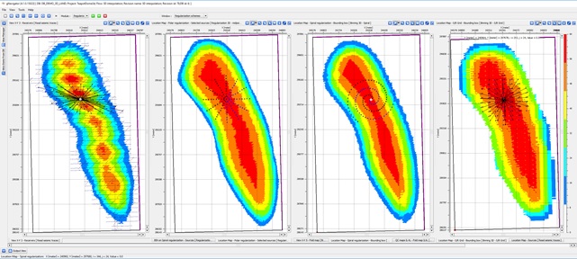
1.Regularization of input data according to virtual (regularized) geometry provided to this module (image below).
2.Regularized gathers from 1 ststage are transformed into Tau-P domain. Then, for each output trace, the algorithm performs local search of events (Eigen values) according to statistics from neighbor traces within predefined apertures. 5D Interpolation module uses high-resolution local linear radon filter with L0-norm, which is very effective for irregular input geometry.
3.Inverse transformation, from Tau-p to T-X domain, into geometry of output traces.
This module has two sub-sequences:
•Sub-sequence–IN: used in order to apply additional filtering in input data prior transformation to Tau-P domain.
•Sub-sequence–OUT: used in order to apply additional filtering on interpolated trace data after inverse transformation.
Input data
Input DataItem
Input SEG-Y data handle
Link to input seismic data. That handle can refer to Seg-Y file of input data or internal seismic format handle.
Input sorted headers
Trace headers of original seismic data.
In case of external Seg-Y file used as an input, the User should check that all geometry information accurately filled in trace headers:
•Source/Receiver/Bin coordinates and elevations
•Source / Receiver Line and SP numbers
•Accurate binning information (Inline / Crossline )
Output headers
Trace headers of seismic data after regularization
Those trace headers define the actual regularized geometry which will be used by 5DI module. Those can be either original geometry or regularized geometry created by one of existing regularization schemes in g-Platform: Archimedes Spiral, Polar or Source/Receiver orthogonal grid.
Parameters
Output file name
Output file name. This is a nick name for the output seismic that will be used to save output interpolated seismic into internal data base
Write direct
In case this check box selected, 5DI module will store output traces in the same order as defined by regularized gathers sorting. Otherwise, saving the interpolated gathers will be done in Append mode – according to execution sequence.
NMO
In order to optimize the process of 5D interpolation and storage use, there is an additional mode, which allows providing seismic data without move out correction.
In case provided seismic does not have NMO (or other move out) applied to the data, you need to select [Gathers without NMO] in [Input gathers type] combo-box. In such case, few parameters such as [Vrms model], [Replacement velocity – V0] and [Datum] need to be defined. The program will use those to shift data prior the actual execution and will save storage and manual work required to create moved-out gathers prior deploying 5DI.
Input gathers type
Choose the option from the drop down menu. By default NMO Gathers
Vrms model
In case the Input gathers type chosen as "Gathers without NMO" then the user should provide the Vrms model
Stretch factor
Define the NMO stretch factor
Shift to datum
By default TRUE. In this case, the user should provide the datum value in the next parameter "Datum"
Datum
As per the previous parameter choice, provide the datum value.
V0
Provide the replacement velocity.
Inline aperture
Used for selecting traces which Source/Receiver coordinates occurs within ellipse defined from Source/Receiver coordinate of each given interpolated trace (see pic #1)
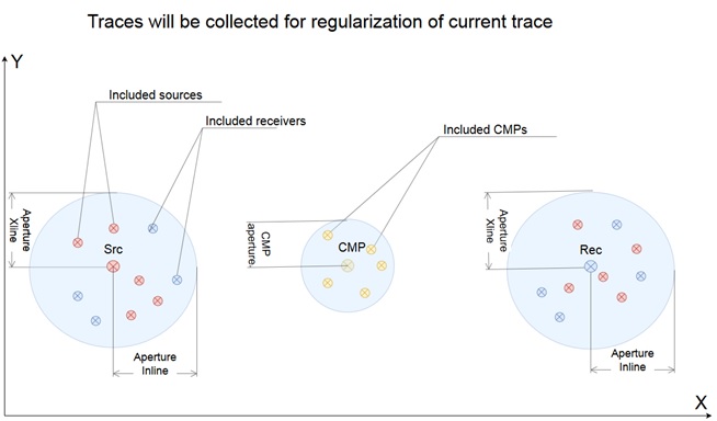
Crossline aperture
Used for selecting traces which Source/Receiver coordinates occurs within ellipse defined from Source/Receiver coordinate of each given interpolated trace (see pic #1)
Window selection
Parameter in milliseconds that define the window in Tau-p domain for events selection
P min
Minimum p-value for transform data from t-x into tau-p domain
This parameter must be chosen carefully since the run time of this process increases by square of the number of P-values
P max
Maximum p-value for transform data from t-x into tau-p domain
This parameter must be chosen carefully since the run time of this process increases by square of the number of P-values
Delta P
Amount of modeling waves. The quality will increase with smaller value - should be approximately equal to sample rate.
That parameter must be chosen carefully since the run time of this process increases by square of the number of P-values
Number of iterations
Number of iterations of Radon transform. Number of iterations of Radon transform. At each iteration, peaks are chosen and used in following iteration for more accurate tau-p transformation.
Calculation area
Calculation area for processing
First inline number(-1 no limit)
First inline number
Last inline number(-1 no limit)
Last inline number
First crossline number(-1 no limit)
First crossline number
Last crossLine number(-1 no limit)
Last crossline number