![]()
![]()
| Shot point numbers are key components in the seismic data acquisition. They carries the positional information of a particular shot gather. During the acquisition, Shot Points may be misaligned or mispositioned from the true position. Also, the distance between two consecutive shot gathers may not be constant. Due to the wrong positioning of shot points, the geometry may be incorrect or the final stack section may not geologically correct. To avoid this, we must correct the SP numbers where necessary. |
| This module performs source/receiver number correction (renumbering) for 2D seismic data. It calculates new source/receiver number and write sit into trace header. Also the procedure has optional possibility to merge sources by user defined minimum distance between each other and offset recalculation. |
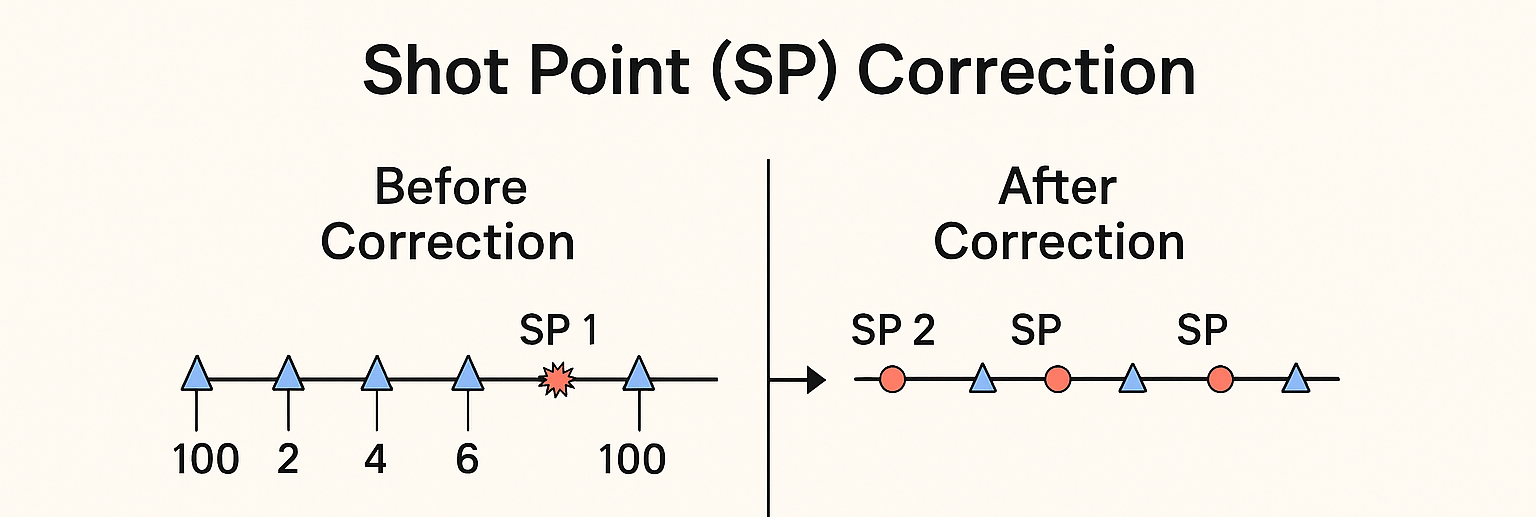
Before Correction
•The diagram shows a straight survey line.
•Blue triangles represent receivers.
•Red star or circle symbols represent sources (shot points).
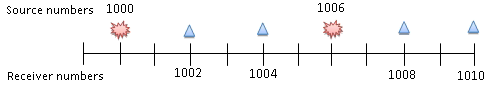
•The numbers (1000, 1002, 1004, etc.) represent receiver numbers, while 1000 and 1006 represent source (SP) numbers.
In this case:
•The sources are not aligned properly with the receivers.
•SP 1000 and SP 1006 may not match the designed geometry — they could be shifted in position due to navigation or operational errors.
•This causes inconsistent offsets (distance between source and receivers) and misalignment with expected spacing.
This is called raw (uncorrected) geometry.
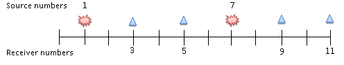
After Correction
•After applying shot point correction, all sources and receivers are aligned uniformly along the line.
•The same color scheme is maintained:
oRed circles = sources
oBlue triangles = receivers
•The spacing between them is corrected to nominal design spacing (for example, 25 m or 50 m apart).
•The corrected SPs are renumbered logically (e.g., SP 1000, 1002, 1004, 1006, 1008, 1010).
Now:
•The geometry becomes consistent.
•Offsets and midpoints can be recalculated accurately.
•This ensures that stacking, velocity analysis, and migration in processing are based on true physical geometry.
![]()
![]()
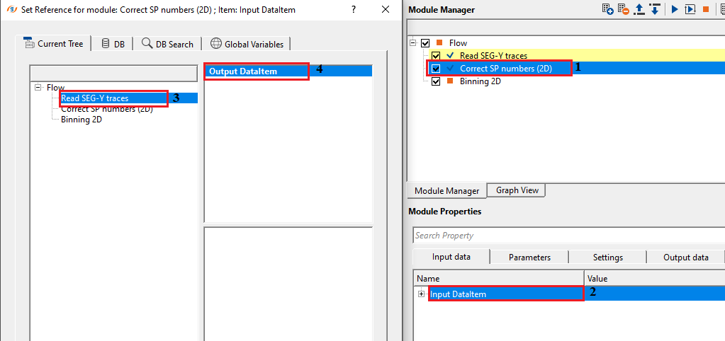
Input DataItem - connect/reference to the Output DataItem. It contains all the information including trace headers information.
Input SEG-Y data handle - connect/reference to Output SEG-Y data handle. It must be connected to Read seismic traces/Read SEG-Y Traces.
Input trace headers - connect/reference to Output trace headers
Input gather - connect/reference to Output gather.
Input stack line - these are not required and if the user connects/reference to Output DataItem, they will automatically get all the information.
Input crooked line - this is not mandatory.
Input bin grid - not mandatory
Input sorted headers - connect/reference to output sorted headers. Not mandatory.
![]()
![]()
Alternative calculation - when enabled (default: on), this mode uses a spatial interpolation approach to assign new SP numbers to receivers. The algorithm builds a unified map of all source and receiver locations, then interpolates receiver SP numbers from known source SP numbers using either Kriging (if Use kriging is enabled) or a picket-based nearest-neighbour distance method. This approach handles situations where receivers do not have reliable SP numbers in the original field headers. When disabled, the module uses the legacy sequential renumbering algorithm, which walks through all station locations ordered by distance from the line centre, interpolates SP values between source control points, and extrapolates beyond the ends of the line.
Use this option (enabled) for most 2D land surveys where receiver SP numbers need to be derived from source positions. Disable it only if the legacy sequential renumbering behaviour is specifically required.
Alternative calculation - true - By default, YES.
Use kriging - this is a spatial interpolation method used to fix the erroneous or missing SP positions based on the neighboring shot points.
Type correction { Receiver, Receiver and source } - controls which station types receive corrected SP numbers. Default: Receiver.
Receiver — only receiver SP numbers are recalculated and written to trace headers. Source SP numbers are assumed to be correct in the original field data and are used as reference control points to interpolate receiver SPs along the line. This is the appropriate setting for most 2D surveys where sources have reliable SP numbers from the field recording system but receivers do not.
Receiver and source — both receiver and source SP numbers are recalculated. The module assigns new SP numbers to all unique station locations (both sources and receivers combined) based on their physical spacing along the line. Use this option when the original field headers contain unreliable SP numbers for sources as well as receivers, or when SP numbering is completely absent and needs to be generated from scratch.
•Receiver– only receivers number correction. In this case module uses source number for calculating the receiver number
•Receiver and source – receivers and sources number correction. In this case module uses source number and receiver number. Automatically set a start point
Rounding factor - a spatial snapping tolerance applied to source and receiver coordinates before they are grouped into unique station locations. Default: 0 (disabled, in metres).
When set to a value greater than zero, the module truncates each station coordinate to the nearest multiple of this value before determining whether two stations occupy the same position. For example, if the rounding factor is 5 m, a receiver at X=10003.7 m and another at X=10001.2 m will both be snapped to X=10000 m and treated as a single station sharing one SP number. This is essential for surveys where GPS coordinates contain small positioning errors that would otherwise cause nearby stations to be assigned different SP numbers. Set this value to approximately half the expected positional uncertainty in the coordinate data. Leave at 0 when coordinates are clean and precise.
Raw SP Preserve - when enabled, applies a second-pass Kriging interpolation that is anchored to the original (field-recorded) source SP values, so that sources whose SP numbers are unique and consistent in the original data retain their original SP value in the output. Default: off.
Enable this when you want the corrected geometry to honour the original field SP numbering for sources while still correcting receivers. This is useful for quality control — you can compare the SP-to-coordinate map before and after correction to verify that only the expected changes were made. In the Alternative calculation mode, this option controls whether source SP numbers are also passed through the Kriging interpolator (when off) or left unchanged at their original values (when on).
Recalculate offset - when enabled, recalculates the source-receiver offset for every trace after SP numbers have been corrected, and also updates the offset sign so that traces where the receiver SP is less than the source SP carry a negative offset. Default: on.
Keep this option enabled in the vast majority of cases. Recalculating the offset is essential after any SP correction because the new SP values define a revised source-receiver ordering along the line, which changes which traces are up-dip versus down-dip from the source. Correct signed offsets are required for subsequent processing steps such as NMO correction, offset sorting, and migration. Disable this only if you need to preserve the original offset values from the field headers for diagnostic purposes.
Rebuild updated sets of SRC/RCV - when enabled, clears and reconstructs the internal source and receiver station tables from the individual trace headers before the SP correction is applied. Default: off.
Enable this option when the geometry dataset contains stale or inconsistent source/receiver station records — for example, after a partial geometry update, or when merging data from multiple field files that used different SP numbering schemes. Rebuilding the station tables ensures that the SP correction algorithm operates on a clean, trace-by-trace derived set of station positions rather than potentially outdated pre-built lookup tables. In normal workflow this option should remain off, as rebuilding is a slow operation and unnecessary when the station tables are already consistent with the trace headers.
![]()
![]()
Auto-connection - when enabled (default: on), the Output DataItem of this module is automatically connected to the Input DataItem of the next module in the workflow. Uncheck this only if you need to break the automatic data chain and connect modules manually.
Number of threads - sets the maximum number of parallel CPU threads used during the SP correction calculation. Set this to one less than the number of physical CPU cores available on the machine to leave one core free for the operating system. Higher values reduce processing time on large 2D datasets with many receivers.
Skip - when enabled, this module is bypassed entirely and data passes through unchanged. Default: off. Use this to temporarily disable the SP correction without removing the module from the workflow, for example when testing the effect of the correction on downstream processing steps.
![]()
![]()
Output DataItem - the corrected seismic dataset with updated SP numbers and geometry in the trace headers. Connect this to the next module in the processing sequence. The output contains the same traces and amplitudes as the input but with corrected source SP, receiver SP, and (if Recalculate offset is enabled) updated source-receiver offset values. The updated SP-to-coordinate map and elevation profiles are also available in the interactive visualisation views.
Output SEG-Y data handle - generates output SEG-Y data handle item
Output trace headers - generates output trace headers after correct SP numbers (2D) operation. This is updated trace headers information.
Output gather - generates output gather if the connection/reference is an output gather.
Output stack line - generates output stack line if the connection/reference is Output SEG-Y DataItem of either Read SEG-Y traces or Read seismic traces module.
Output crooked line - generates output crooked line if the connection/reference is Output SEG-Y DataItem of either Read SEG-Y traces or Read seismic traces module.
Output bin grid -generates output bin grid if the connection/reference is Output SEG-Y DataItem of either Read SEG-Y traces or Read seismic traces module.
Output sorted headers - generates output sorted headers if the connection/reference is Output SEG-Y DataItem of either Read SEG-Y traces or Read seismic traces module.
There is no information available for this module so the user can ignore it.
![]()
![]()
In this example workflow, we are reading a Geometry assigned SEG-Y dataset using Read SEG-Y traces. All the coordinates, elevations and other information is already available in the trace headers. We need to bin the data to generate the CMP information.
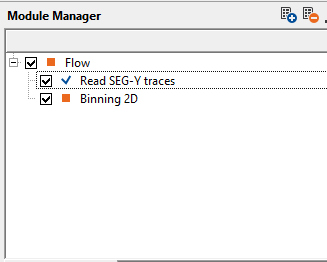
After making the necessary references/connections, Binning 2D module fails with an error message when we select NO option since there are problematic source and receivers.
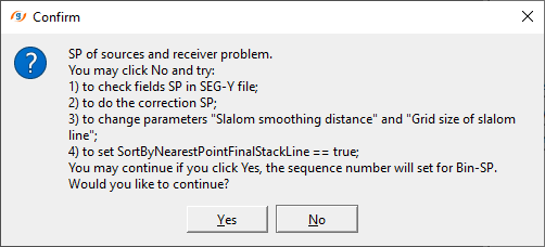
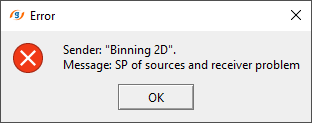
To fix this, we introduce Correct SP numbers (2D) module into the workflow.
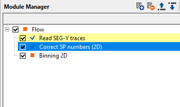
We make the necessary connections/references to Correct SP numbers (2D) module as shown below followed by corresponding parameters.
After executing correct SP numbers (2D) module, we connect/reference Output trace headers to Input trace headers of Binning 2D and execute Binning 2D module again to make sure that the binning works correct.
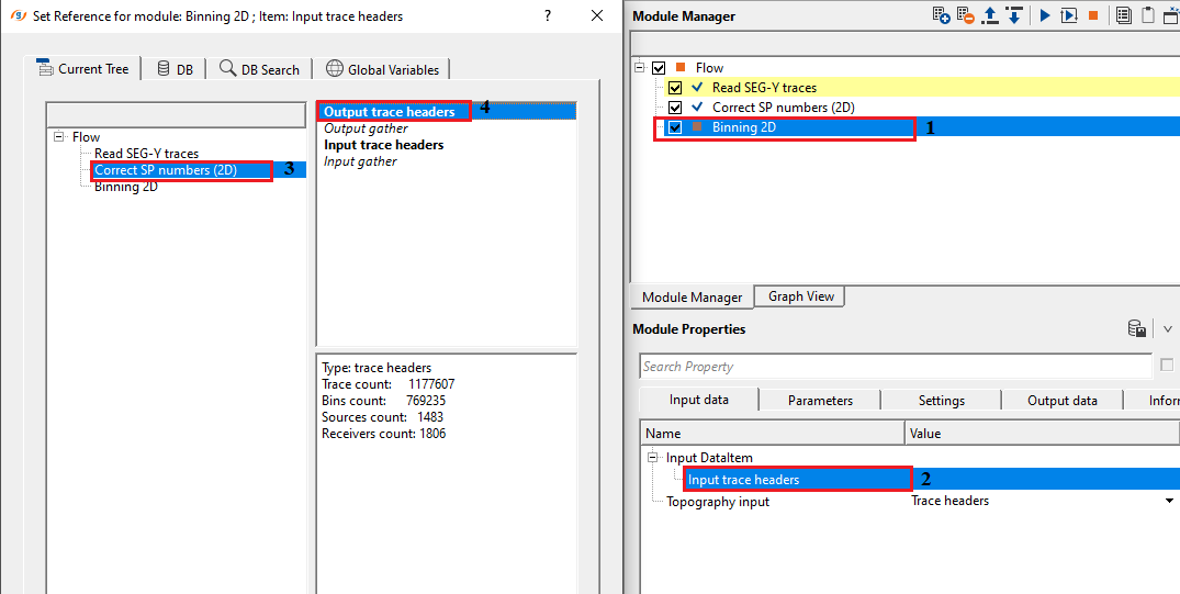
Correct SP numbers (2D) module fixed the error message previously encountered at Binning 2D module. This way, we can correct erroneous SP numbers.
![]()
![]()
There are no action items available for this module so the user can ignore it.
![]()
![]()
YouTube video lesson, click here to open [VIDEO IN PROCESS...]
![]()
![]()
Yilmaz. O., 1987, Seismic data processing: Society of Exploration Geophysicist
 * * * If you have any questions, please send an e-mail to: support@geomage.com * * *