![]()
![]()
This module performs source/receiver number correction (renumbering) for 3D seismic data. It calculates new source/receiver number and writes it into trace header.There are two input data geometry trace headers (“Read seismic traces/Read SEG-Y traces”) and grid (“Binning3D”) required. The grid used for calculation inline, crossline number. Then this numbers used for creation source and receiver numbers. Also module has possibility to fill-up elevation headers from input binning data.
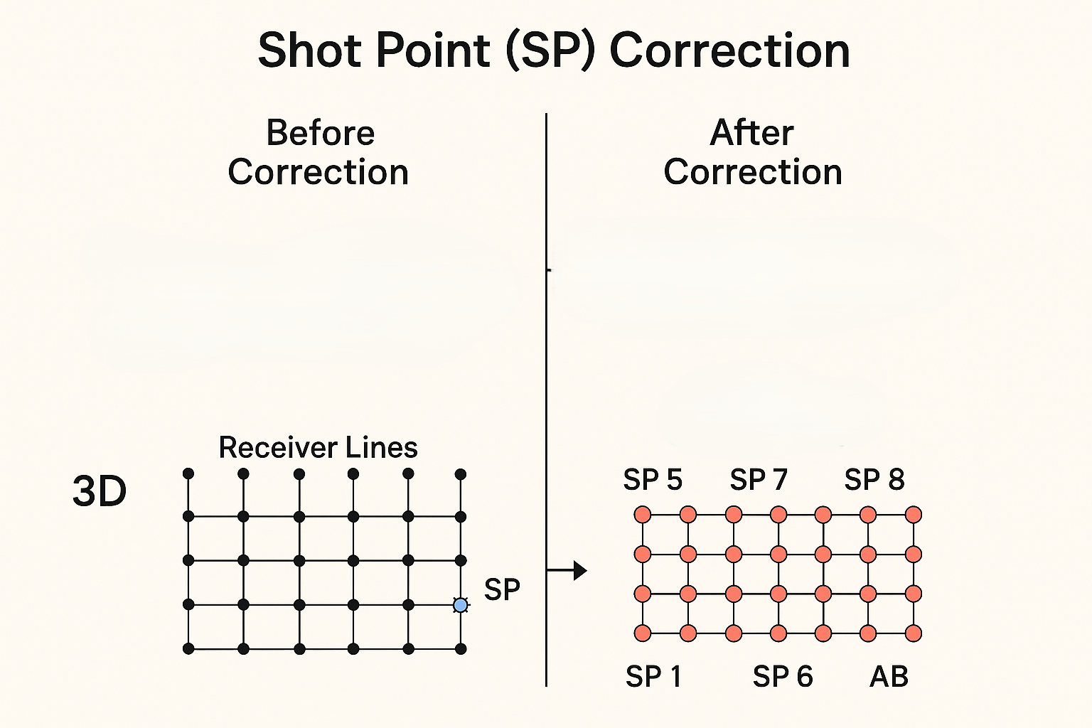
Before Correction
•In 3D seismic acquisition, both sources and receivers are placed on a grid (inline × crossline).
•The black dots represent receiver stations forming receiver lines.
•The blue star (SP) represents a source location that is misplaced — i.e., not exactly on the designed grid intersection.
This can happen due to:
•GPS drift
•Terrain restrictions
•Human or recording errors
•Navigation inaccuracies
As a result, the shot grid is irregular, and binning (assigning traces to grid cells) becomes inaccurate.
After Correction
•After applying shot point correction:
oThe sources (SPs) are repositioned to their correct nominal grid intersections.
oThe grid now forms a clean, uniform 3D matrix of shot and receiver positions.
oEach intersection corresponds to one valid shot-receiver combination.
•The corrected shot points are labeled (e.g., SP1, SP5, SP6, SP7, SP8) to show the new organized pattern.
This ensures that:
•All source–receiver pairs are in the right geometric relation.
•The fold map (number of traces per bin) is accurate.
•The 3D cube built from the geometry is spatially correct.
![]()
![]()
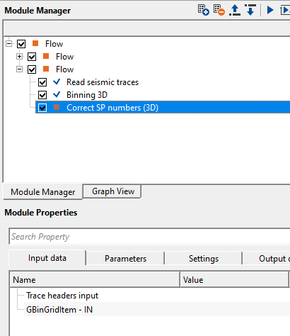
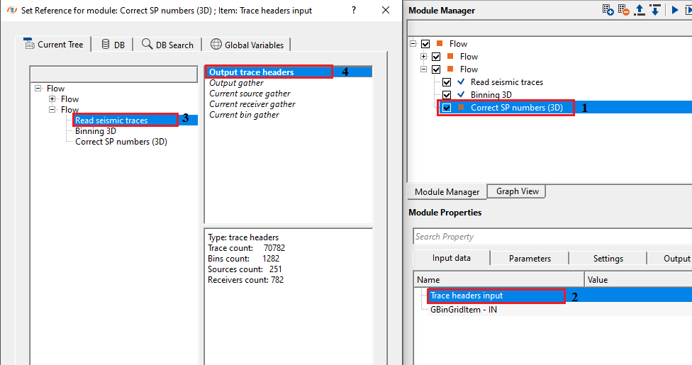
Trace headers input- connect/reference to Output trace headers either from Read seismic traces or Read SEG-Y traces module
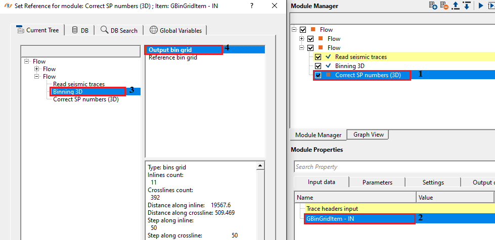
GBinGridItem - IN- connect/reference to Output bin grid in case connecting/referencing to Binning 3D. Alternatively connect/reference to loaded item if the user loaded the previously saved bin grid information by using Load item module. This bin grid information is utilized in generating the source/receiver SP/lines etc.
![]()
![]()
Generate SP (Source) { Composite source, Source line / SP, none }- this option allows the user to generate the Source Shot Point (SP) number. Choose the respective options from the drop down menu. By default, Composite Source.
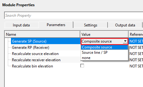
Composite Source - generates a single composite SP number for each source by encoding both the crossline and inline position into one value using the formula: Source SP = (Crossline number × 10000) + Inline number. This produces a unique integer for every source position on the 3D grid and writes it into the source SP trace header field. Use this mode when you need a single unambiguous source identifier that encodes full 2D grid coordinates.
Source line / SP - writes the source numbers as two separate fields: Source line = Crossline number and Source SP = Inline number. Use this mode when downstream processing or output formats require source line and SP as independent trace header fields rather than a composite value.
None - source SP numbers are not recalculated. The original source header values are preserved unchanged. Use this option when source SP numbers are already correct and only receiver renumbering or elevation recalculation is needed.
Generate RP (Receiver) { Composite receiver, Receiver line / RP, none }- this option allows the user to generate the Receiver Shot Point (RP) number. Choose the respective options from the drop down menu. By default, Composite Receiver.
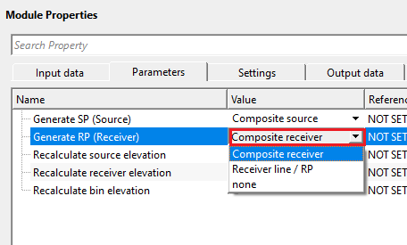
Composite Receiver - generates a single composite RP number for each receiver by encoding both the inline and crossline position into one value using the formula: Receiver SP = (Inline number × 10000) + Crossline number. Note that the axis order is reversed relative to the source composite formula, which ensures sources and receivers produce distinct numeric ranges. This value is written into the receiver SP trace header field.
Receiver line / RP - writes the receiver numbers as two separate fields: Receiver line = Inline number and Receiver SP = Crossline number. Use this mode when downstream processing or output formats require receiver line and RP as independent trace header fields.
None - receiver RP numbers are not recalculated. The original receiver header values are preserved unchanged. Use this option when receiver SP numbers are already correct and only source renumbering or elevation recalculation is needed.
Recalculate source elevation- recalculates source elevation by input topo binning data. By default, FALSE (Unchecked).
When enabled, the source elevation (Z coordinate) stored in each trace header is replaced with the elevation value interpolated from the topography surface stored in the connected bin grid. This is useful when the original source elevation values in the data are unreliable or were recorded incorrectly. If a source location falls outside the extent of the bin grid, the elevation cannot be interpolated and the corresponding trace is flagged as auxiliary (trace identification code set to 2), marking it for exclusion from further processing.
Recalculate receiver elevation- recalculates receiver elevation by input topo binning data. By default, FALSE (Unchecked).
When enabled, the receiver elevation (Z coordinate) stored in each trace header is replaced with the elevation value interpolated from the topography surface stored in the connected bin grid. Use this when receiver elevation values in the raw data are missing or incorrect. As with source elevation, any receiver whose coordinates fall outside the bin grid extent will result in the associated trace being flagged as auxiliary.
Recalculate bin elevation- recalculates bin elevation by input topo binning data (Binning 3D module creates smooth topography so the final elevations will be smooth). By default, FALSE (Unchecked).
When enabled, the midpoint bin elevation stored in each trace header is replaced with the elevation value interpolated from the topography surface stored in the connected bin grid. Because the Binning 3D module generates a smoothed topography surface, the resulting bin elevations will be spatially smooth rather than reflecting sharp terrain variations. Enable this option when you need consistent, smoothed surface elevations at midpoint bin locations for use in subsequent static corrections or depth conversion.
![]()
![]()
Skip- By default, FALSE (Unchecked). When enabled, this module is bypassed entirely and the input trace headers are passed through to the output unchanged. Use this option to temporarily disable SP number correction during workflow testing without removing the module from the processing sequence.
![]()
![]()
Trace headers output- generates updated output trace headers with corrected source and/or receiver SP numbers and optionally updated elevation values. Connect this output to the Trace headers input of the next module in the processing workflow. Traces whose source or receiver coordinates fell outside the bin grid extent are flagged with trace identification code 2 (auxiliary), allowing them to be identified and handled separately in subsequent steps.
There is no information available for this module so the user can ignore it.
![]()
![]()
In this example workflow, we connect/reference Trace headers input to Output trace headers, GBinGridItem to Output bin grid.
![]()
![]()
There are no action items available for this module.
![]()
![]()
YouTube video lesson, click here to open [VIDEO IN PROCESS...]
![]()
![]()
Yilmaz. O., 1987, Seismic data processing: Society of Exploration Geophysicist
 * * * If you have any questions, please send an e-mail to: support@geomage.com * * *