Sharpening of the seismic data
![]()
![]()
What is a Diff Filter?
A Diff filter (short for differentiation filter) is a filter that computes the second derivative of a seismic signal. In other words, A diff filter measures how quickly the trace is bending or changing. It highlights sharp events (reflections) and suppresses slow trends.
It is also called:
•Second derivative filter
•Laplacian filter
•Edge enhancer
How Does It Work?
First derivative = rate of change
Tells us how fast the signal is going up or down.
Second derivative = change of the change
Tells us where the signal bends sharply (like corners).
A reflection is a sudden change in amplitude - this creates large second derivatives, so reflections become sharper and more visible.
Slow background trends (low frequencies) - small second derivatives - get suppressed.
What Does the Diff (Second Derivative) Filter Do to Seismic Data?
Highlights edge-like features - Reflections, faults, thin beds become clearer.
Reduces long-wavelength trends
Removes:
•low-frequency noise
•gradual amplitude changes
•baseline drift
•ground roll (partially)
Acts like a “sharpening filter” - It makes seismic events appear sharper and more detailed.
How Is the Diff Filter Applied?
Time-domain form:
A common second-derivative operator is: y(t) = x(t+1) – 2x(t) + x(t-1)
This is the discrete second derivative.
•If the trace is flat then output = 0
•If it changes slowly then small output
•If it changes sharply then big output (highlighted)
Frequency-domain form:
The second derivative multiplies the spectrum by: -(2πf)2
This means:
•Low frequencies suppressed
•High frequencies enhanced. This is why diff filters behave like high-pass filters.
Where Is Diff Filtering Used in Seismic Processing?
•As a pre-conditioning step - Before deconvolution or inversion.
•To sharpen events in migrated stacks - Imaging looks crisper.
•To highlight thin beds - Second derivative produces two strong opposite-polarity peaks for thin reflectors.
•To remove low-frequency noise or sag - Especially useful in VSP and some land data.
•In attribute analysis - Second derivative - curvature-like structural attributes.
Advantages
•Very simple & fast
•Enhances reflectivity
•Emphasizes thin layers
•Removes low-frequency noise
•Improves resolution
Disadvantages
•Can amplify high-frequency noise
•Edges are exaggerated → may need smoothing
•May distort amplitude if overused
![]()
![]()
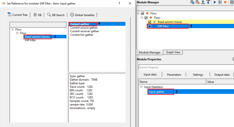
Input DataItem
Input gather - connect/reference to pre or post-stack gather.
Connect this item to any seismic gather in the workflow — pre-stack common-midpoint (CMP) gathers, common-offset gathers, or post-stack migrated sections are all valid inputs. The module processes each trace independently sample by sample, so the gather geometry (number of traces, sample interval, record length) is preserved exactly in the output. The input data must be loaded into memory for processing; ensure the upstream Read module has its Load data to RAM option set to Yes.
![]()
![]()
Diff type { First derivative, Second derivative } - select the differentiators from the drop down menu. By default, Second derivative.
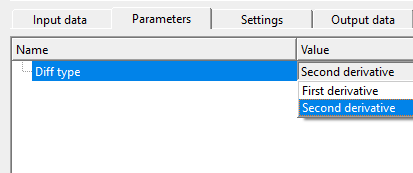
First derivative - tells us how fast the signal is going up or down.
Second derivative - tells us where the signal bends sharply (like corners).
The Second derivative mode (default) applies the discrete Laplacian operator: the value x(t+1) − 2·x(t) + x(t−1) is computed and added to the original sample. This additive design means the output is a sharpened version of the input — the underlying reflectivity structure is retained and amplified rather than replaced. The result emphasises rapid amplitude changes (reflections, thin-bed tops and bases) while attenuating smooth, slowly varying trends. The first and last samples of each trace are left unchanged because the operator requires one neighbour on each side.
The First derivative mode computes the rate of change of the signal amplitude between adjacent samples. It is most useful when the goal is to detect the flanks of a reflection wavelet or to convert a zero-phase wavelet into a 90-degree phase version. Use this mode when you need to highlight lateral amplitude gradients or wavelet onset/termination rather than overall wavelet sharpness.
![]()
![]()
Auto-connection - By default, TRUE(Checked).It will automatically connects to the next module. To avoid auto-connect, the user should uncheck this option.
When checked (default), the output gather of this module is automatically wired to the input of the next module in the workflow chain. Uncheck this option if you want to manually control which downstream module receives the filtered data, for example when the output needs to be routed to multiple branches simultaneously.
Bad data values option { Fix, Notify, Continue } - This is applicable whenever there is a bad value or NaN (Not a Number) in the data. By default, Notify. While testing, it is good to opt as Notify option. Once we understand the root cause of it,
the user can either choose the option Fix or Continue. In this way, the job won't stop/fail during the production.
Notify - It will notify the issue if there are any bad values or NaN. This will halt the workflow execution.
Fix - It will fix the bad values and continue executing the workflow.
Continue - This option will continue the execution of the workflow however if there are any bad values or NaN, it won't fix it.
Calculate difference - This option creates the difference display gather between input and output gathers. By default Unchecked. To create a difference, check the option.
Enabling this option produces a third gather that contains the element-wise difference between the filtered output and the original input. This QC gather isolates the component added by the filter (the second-derivative term itself) and is useful for verifying that the filter is modifying the data as expected without altering unintended frequency bands. The difference gather appears as a separate display panel in the vista view and is also available as the Gather of difference output connector.
Number of threads - One less than total no of nodes/threads to execute a job in multi-thread mode. Limit number of threads on main machine.
Controls how many parallel CPU threads are used when running this module in a multi-threaded workflow. Set this to one fewer than the number of available processor cores on the machine to leave one core free for the operating system and g-Platform's internal management tasks. Because the Diff filter performs a very lightweight per-sample arithmetic operation, the default setting is adequate for most production datasets; increasing the thread count provides the most benefit when processing very large volumes with many thousands of traces per gather.
Skip - By default, FALSE(Unchecked). This option helps to bypass the module from the workflow.
When Skip is enabled, this module passes data through to the next step in the workflow without applying any filtering. Use this option to quickly compare the effect of the Diff filter against the unfiltered data by toggling Skip on and off without disconnecting the module from the workflow chain.
![]()
![]()
Output DataItem
Output gather - generates output gather
The primary output is a gather with the same dimensions (number of traces, number of samples, sample interval) as the input. Each trace contains the sharpened signal — the original amplitude values with the discrete second derivative (or first derivative, depending on the Diff type setting) added in. Connect this item to the next processing module, a display panel, or an output writer in the workflow. The output is suitable for further processing steps such as stacking, migration, or AVO analysis.
Gather of difference - generates difference gather if opted.
Available only when the Calculate difference option is enabled. This output gather contains the sample-by-sample difference between the output and the input, which is equivalent to the pure derivative component added by the filter. It is a powerful QC tool: the difference gather should contain only the high-frequency sharpening contribution with no low-frequency signal. If significant low-frequency energy appears in the difference gather, it may indicate unexpected interaction with the data (for example, very abrupt amplitude changes caused by noise or data artefacts).
The Diff filter module has no custom action verbs. There are no additional buttons or interactive controls beyond the standard parameter settings described above.
![]()
![]()
In this example workflow, we are reading a post stack gather by using Read seismic traces module. Make sure to change Load data to RAM from NO to YES.
Select the appropriate differentiators from the drop down menu. We've selected second derivative for this exercise.
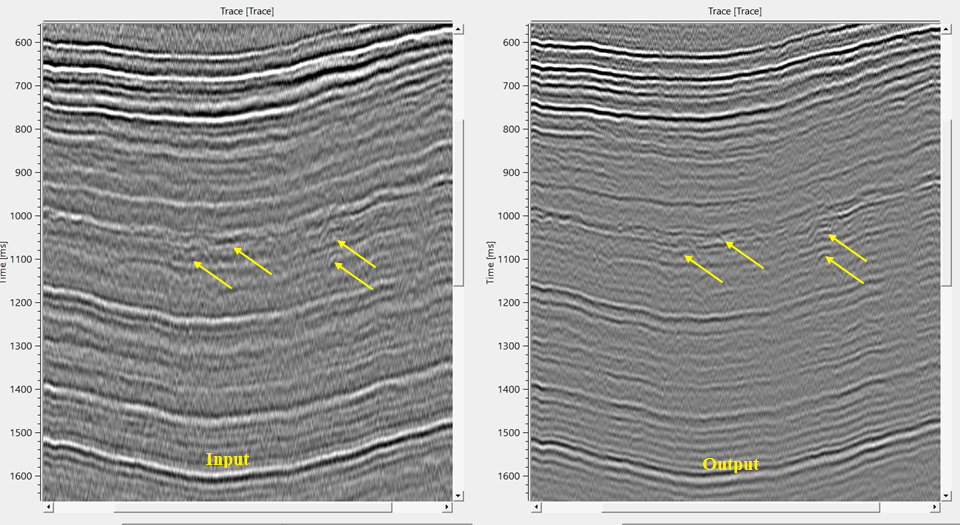
If we observe the output gather, it is more sharp and revealing the finer details which are masked by the low frequency content in the input gather.
![]()
![]()
There are no action items available for this module so the user can ignore it.
![]()
![]()
YouTube video lesson, click here to open [VIDEO IN PROCESS...]
![]()
![]()
Yilmaz. O., 1987, Seismic data processing: Society of Exploration Geophysicist
 * * * If you have any questions, please send an e-mail to: support@geomage.com * * *