Linear noise attenuation
![]()
![]()
This filter module works in FK domain, which represents two dimensional Fourier transform (FT) over time and space, where F is frequency (FT time) and K is wave number (FT space) (Fig.1). The algorithm removes energy from seismic data by applying user-defined polygon in frequency-wave number domain. You can also use another module for this task called LNA (Linear Noise Attenuation), because it has min and max velocity parameters for filter definition instead of polygon.
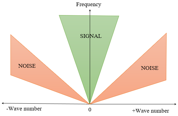
Fig.1 FK domain scheme.
![]()
![]()
Clear all picking - remove a polygon for rejection/saving data in FK spectrum.
Load picking - load from file a polygon for rejection/saving data in FK spectrum.
Save picking - save to file a polygon for rejection/saving data in FK spectrum.
![]()
![]()
Input Gather - input seismic gather, NMO-corrected (not strict, but reasonable), any sorting (usually source gather).
Picking item - Load FK polygon in a pre-existing picking item.
FK picking item - polygon for the FK filter. The user may need to make picks in the FK analysis – manual window before the FK spectrum will load properly. Can also load in pre-existing FK picking items.
![]()
![]()
Distance between traces (meters) in the input gather, need to calculate FK spectrum. By default it is -1, it means read offsets from traces headers and calculate delta offset automatically.
Mute inside - remove data inside the user-defined polygon:
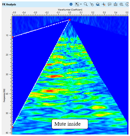
Fig.2 FK spectrum with mute inside parameter.
Mute Outside - remove data outside the user-defined polygon:
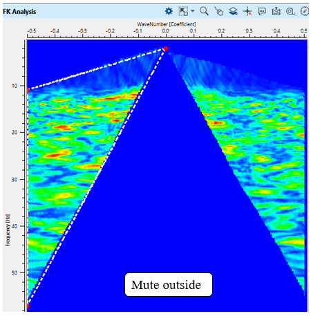
Fig.2 FK spectrum with mute outside parameter.
Asymmetric - remove only one inside of the FK spectrum in accordance with the polygon:
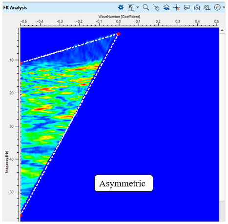
Fig.3 FK spectrum with asymmetric parameter.
Symmetric - remove both sides (-/+ K) of the FK spectrum in accordance with the polygon:
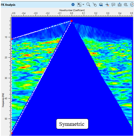
Fig.4 FK spectrum with symmetric parameter.
Tapering zone for polygon in FK domain in order to avoid edge-effects.
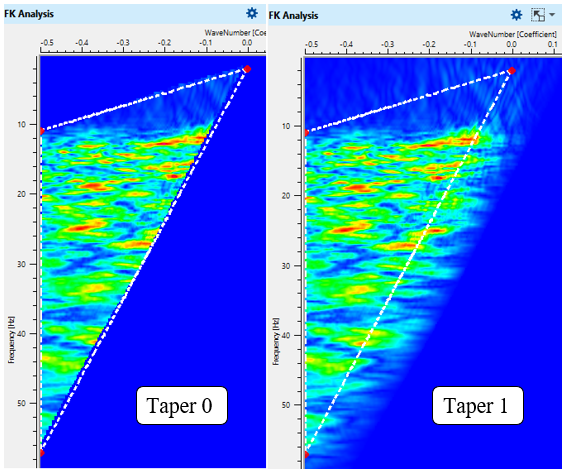
Fig.5 FK spectrum with different taper parameters.
Tapering zone along the X axis (wavenumber) in FK domain in order to avoid edge-effects.
Tapering zone along the Y axis (frequency)Y in FK domain in order to avoid edge-effects.
![]()
![]()
Skip - switch-off this module (do not use in the workflow).
Auto-connection - module is connected with previous (and next) modules in the workflow by default.
Bad data values option
There are 3 options for corrupted (NaN) samples in trace:
Fix - fix corrupted samples.
Notify - notify and stop calculations.
Continue - continue calculations without fixing.
Calculate difference - perform conventional subtraction input and output gathers (DIFF = IN - OUT), and result is displayed on the difference visual vista.
Number of threads - perform calculation in the multi-thread mode.
![]()
![]()
Output gather - input seismic data minus linear noise (according to the polygon).
![]()
![]()
A test seismic data set is the Poland 2D (land) line, you Poland 2D line that is accessible on the internet free or it is also included to the g-Platform installation (C: \Program Files (x86)\Geomage \gPlatform \demodata\ Poland_2D_Vibroseis_LINE_01).
An example of the workflow for FK filtering:
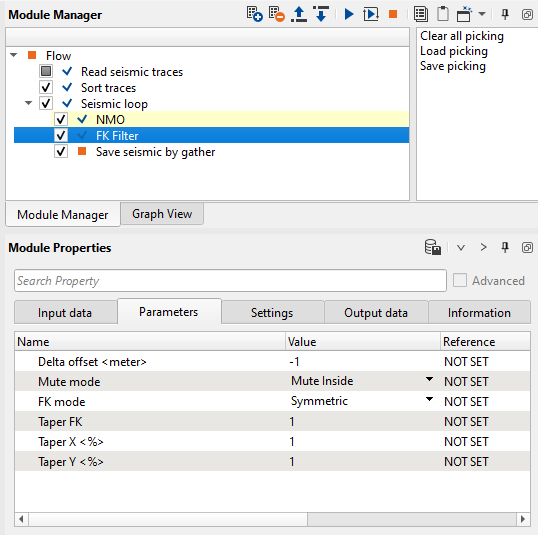
Fig.6 Workflow example.
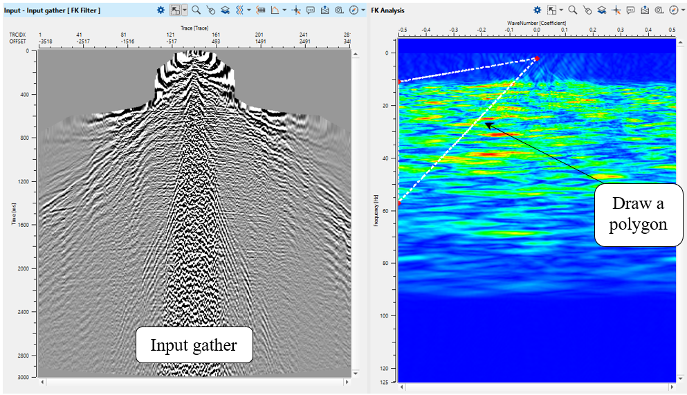
Fig.7 Input gather (left) and its FK spectrum with polygon for rejection (right).
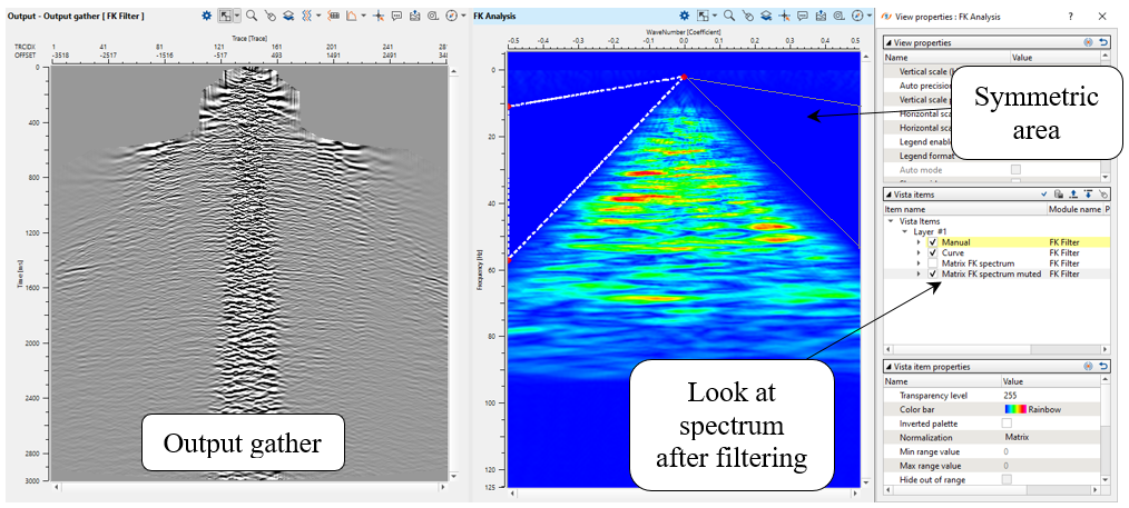
Fig.8 Output gather (left) and its FK spectrum with polygon for rejection (right).
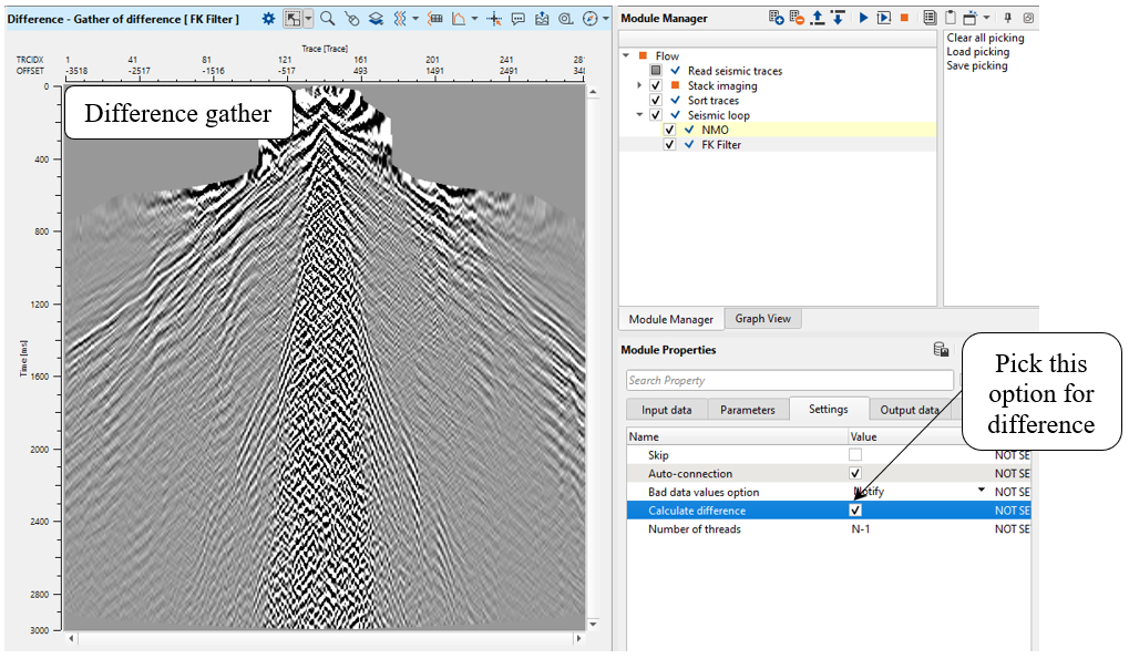
Fig.9 Difference gather (left) and parameter for its calculation (right).
![]()
![]()
YouTube video lesson, click here to open [VIDEO IN PROCESS...]
![]()
![]()
Yilmaz. O., 1987, Seismic data processing: Society of Exploration Geophysicists
Shettar A., 2019, F-K Filtering for Seismic Data Processing
 If you have any questions, please send an e-mail to: support@geomage.com
Description
The FK Filter module attenuates coherent linear noise in seismic gathers by transforming data into the frequency-wavenumber (F-K) domain, zeroing or muting energy within a user-defined region of the spectrum, and transforming the result back to the time-offset domain. It is the primary tool for suppressing linear events with specific apparent velocities, such as ground-roll, guided waves, air-blast arrivals, and other coherent noise trains that are separable from reflection energy in the F-K plane.
The module supports two working modes. In Fan filter mode the rejection zone is defined analytically by a pair of apparent velocities and a frequency band, which automatically constructs a fan-shaped polygon in the F-K plane. In Manual polygon mode the user draws an arbitrary closed polygon directly on the displayed F-K spectrum by clicking to add vertices and right-clicking to remove them. Both modes support symmetric application to suppress noise travelling in both the positive and negative wavenumber directions simultaneously. An optional pre-processing Automatic Gain Control (AGC) step improves the visual quality of the F-K spectrum and can help the filter operate more uniformly across the trace length.
Input data
Input gather
The seismic gather to be filtered. This is typically a common-shot, common-midpoint, or common-receiver gather containing the linear noise events you want to attenuate. Connect the gather output from the preceding processing step to this input.
Picking item
An optional spectral analysis picking item that defines a pre-mute polygon applied in the F-K domain before the main filter polygon. When connected, the input gather is first split into inside-polygon and outside-polygon portions; only the outside portion is passed through the FK filter, and the inside portion is recombined with the filtered result afterward. This allows protection of specific spectral zones from filtering.
FK picking item
Stores the manually drawn polygon points in the F-K domain. This item is used internally when Work mode is set to Manual polygon. You can save and reload polygon picks using the Custom Actions, making it possible to apply the same polygon to multiple processing runs without re-drawing it each time.
Parameters
FK transformation
These parameters define the frequency and wavenumber window over which the 2D FFT is computed and the F-K spectrum is displayed. Restricting the window to the range of interest reduces computation time and focuses the spectrum on the frequencies and wavenumbers relevant to the noise being targeted.
Min frequency
The lower boundary of the frequency axis in the F-K spectrum, in Hz. Default: 0 Hz. Set this to a value above 0 if the very lowest frequencies do not contain noise energy and you want to exclude them from the transform window. Must be less than Max frequency.
Max frequency
The upper boundary of the frequency axis in the F-K spectrum, in Hz. Default: 125 Hz. Set this to the Nyquist frequency of your data or lower if the noise is confined to a narrower band. Reducing this value speeds up computation when the noise energy is well below Nyquist.
Min K
The minimum wavenumber (K) value shown on the horizontal axis of the F-K spectrum. Default: -0.5. Wavenumber is expressed as cycles per unit distance. The valid range is -100 to 100. Negative wavenumbers correspond to events travelling in the negative offset direction. Set this to a narrower range to zoom into the part of the spectrum where noise is visible.
Max K
The maximum wavenumber (K) value shown on the horizontal axis of the F-K spectrum. Default: 0.5. Valid range is -100 to 100. Together with Min K, this defines the width of the wavenumber axis. Increase this value when you need to see high-wavenumber noise or when the trace spacing is large.
Delta offset
The assumed trace spacing (offset increment) in metres used when computing the F-K transform. Default: -1 m (automatic — the module derives the spacing from the actual trace offsets in the gather). Set this manually only if the gather has irregular trace spacing or if you want to override the auto-detected value. After execution the actual computed delta offset is reported in the read-only Calculated Delta offset output. Units are metres.
Mute mode
Controls whether energy inside or outside the drawn polygon (or fan-filter boundary) is zeroed out. Default: Mute Inside. Use Mute Inside when the polygon encloses the noise zone you want to remove. Use Mute Outside when the polygon encloses the signal you want to preserve, and everything outside the polygon should be rejected.
Work mode
Selects between the two polygon-definition methods. Default: Fan filter. When set to Fan filter, the FK transformation container and the fan-filter parameters (V1, V2, F1, F2, Fan filter mode) are active, and the filter boundary is computed automatically from velocity and frequency limits. When set to Manual polygon, the FK mode and the FK picking item become active, and you define the rejection zone by clicking vertices directly on the F-K spectrum display.
Manual polygon mode parameters
These parameters are active only when Work mode is set to Manual polygon. In this mode you draw the rejection polygon interactively on the F-K spectrum display: left-click to add a vertex, drag an existing vertex to move it, and right-click near a vertex to remove it. The filter is applied once you execute the module.
FK mode
Controls whether the manually drawn polygon is applied only on the side of the F-K spectrum where it was drawn, or mirrored symmetrically across the zero-wavenumber axis. Default: Asymmetric. Set to Symmetrical when the noise appears on both the positive and negative wavenumber sides simultaneously (for example, ground-roll that appears in both forward and reverse apparent velocity directions). Using Symmetrical mode avoids drawing two separate polygons for the same noise at positive and negative wavenumbers.
Fan filter mode parameters
These parameters are active only when Work mode is set to Fan filter. The fan-shaped rejection zone is defined by two velocity limits and a frequency band. Signals whose apparent velocity falls between V1 and V2, and whose frequency falls between F1 and F2, are attenuated. The boundary lines of the fan in the F-K plane are the lines F = V1 * K and F = V2 * K. Adjusting these parameters updates the overlaid fan polygon on the F-K spectrum in real time so you can preview the filter zone before executing.
Fan filter mode
Determines which part of the wavenumber axis the fan filter acts on. Default: Symmetrical. Options are: Positive (reject noise in the positive wavenumber fan only), Negative (reject noise in the negative wavenumber fan only), or Symmetrical (reject noise in both fans simultaneously). Use Symmetrical when the same noise type appears in both directions — this is the most common choice for ground-roll attenuation.
V1
The lower apparent velocity boundary of the fan-shaped rejection zone, in m/s. Default: 300 m/s (minimum 1 m/s). Set this to the lowest apparent velocity of the noise you want to suppress. For typical ground-roll, values around 200–500 m/s are common. V1 must be less than V2.
V2
The upper apparent velocity boundary of the fan-shaped rejection zone, in m/s. Default: 600 m/s (minimum 1 m/s). Set this to the highest apparent velocity of the noise train. Using a wider range (larger difference V2 - V1) attenuates more of the spectrum but risks removing some near-surface reflections if they overlap in velocity with the noise. V2 must be greater than V1.
F1
The lower frequency limit of the fan filter zone, in Hz. Default: 20 Hz (minimum 0 Hz). Frequencies below F1 are not affected by the fan filter. Set this to a value that is safely below the lowest frequency of the noise without cutting into signal energy. F1 is automatically clamped to be no lower than Min frequency from the FK transformation window.
F2
The upper frequency limit of the fan filter zone, in Hz. Default: 80 Hz (minimum 0 Hz). Frequencies above F2 are not affected by the fan filter. Set this to a value just above the highest frequency of the noise. F2 is automatically clamped to be no higher than Max frequency from the FK transformation window. F2 must be greater than F1.
Taper and AGC parameters
Tapering smooths the edges of the muted region in the F-K domain to reduce ringing and edge artefacts in the output gather. AGC normalises trace amplitudes before the transform so that deep, low-amplitude events are represented equally well in the F-K spectrum during interactive picking, but after filtering the original amplitude envelope is restored.
Taper FK
The fractional width of the cosine taper applied along the boundary of the muted polygon or fan filter in the F-K domain. Default: 0.2 (20% of the polygon width). A taper of 0 applies a hard cut with no transition zone, which can produce spatial ringing. Increasing the taper value broadens the transition zone and produces a smoother result at the cost of slightly less aggressive noise rejection near the polygon boundary. Values between 0.1 and 0.3 are typical.
Taper X
The fractional taper width along the wavenumber (K) axis of the spectral analysis picking polygon, expressed as a fraction of the polygon width. Default: 0.01 (1%). This parameter applies when a spectral analysis picking polygon is connected via the Picking item input. A small non-zero value prevents a perfectly sharp boundary along the K axis and avoids hard-cut artefacts at the polygon edges in the wavenumber direction.
Taper Y
The fractional taper width along the frequency axis of the spectral analysis picking polygon, expressed as a fraction of the polygon height. Default: 0.05 (5%). This parameter applies in conjunction with Taper X when a spectral analysis picking polygon is active. A slightly larger default than Taper X reflects that frequency-axis transitions typically need a broader taper to avoid spectral ringing in the time domain.
Use AGC
When enabled, an Automatic Gain Control (AGC) is applied to the input gather before computing the F-K transform. Default: On. The AGC balances the amplitude of all traces so that the F-K spectrum shows noise events at all offsets and depths with equal prominence, which makes interactive polygon picking much easier. After the filtered spectrum is transformed back to the time-offset domain, the original amplitude scaling is reapplied (the AGC gain is reversed), so the output gather retains the correct relative amplitudes. Disabling AGC may be preferable when you want the F-K filter to behave consistently with the actual amplitude distribution of the data.
AGC Window
The length of the sliding window used to compute the AGC gain envelope, in seconds. Default: 0.5 s (minimum 0.001 s). This parameter is visible only when Use AGC is enabled. Shorter windows produce more aggressive equalisation that may over-enhance noise in quiet zones; longer windows produce a gentler gain curve that better preserves the original amplitude envelope shape. A value between 0.2 s and 1.0 s is typical for most surveys.
Output data
Output gather
The filtered seismic gather in the time-offset domain, with the noise energy in the selected F-K zone attenuated. The output has the same dimensions and header values as the input gather. Connect this to the next processing step in your workflow.
Gather of difference
The difference between the input and output gathers (input minus output), showing only the noise energy that was removed by the filter. This QC output is useful for verifying that the filter is attenuating noise without damaging primary reflection energy. If you see clear reflection hyperbolas in the difference gather, your polygon may be too broad and is removing signal as well as noise.
Calculated Delta offset
A read-only output parameter that reports the actual trace spacing (in metres) used when computing the F-K transform. When Delta offset is set to -1 (automatic), this value shows what was derived from the trace headers. Check this value to confirm that the module has detected the correct trace interval for your gather geometry.
Matrix spectrum
The full 2D F-K amplitude spectrum of the input gather (after any AGC and spectral-analysis-polygon pre-mute). This matrix is displayed in the FK spectrum analysis view and is used as the background display when interactively drawing the rejection polygon or fan filter boundary.
Matrix spectrum mute
The F-K amplitude spectrum after the mute polygon has been applied — i.e., the spectrum that was used to reconstruct the output gather. Compare this with Matrix spectrum to confirm that the polygon is muting the intended noise zone and that no signal energy has been removed.
Custom actions
Clear all picking
Removes all manually drawn polygon vertices for the current gather. After confirmation, the FK picking item is cleared and the display is updated. Use this action to start the polygon picking over from scratch when the current polygon does not adequately isolate the noise zone.
Load picking
Opens a file browser to load a previously saved polygon picking from a .corr file. The loaded polygon is immediately applied to the current gather and the F-K spectrum display is updated. This allows you to reuse the same rejection polygon across multiple processing jobs or data sets without re-picking interactively. The input gather must be connected before loading a picking file.
Save picking
Opens a file browser to save the current polygon picking to a .corr file. Saving the polygon is recommended after interactive picking so it can be loaded again later or shared with other processing operators. If no polygon points have been defined, the save will not write a file.