Changing the domain from time to depth to frequency and vice versa
![]()
![]()
What Are “Domains” in Seismic Processing?
In seismic data, every reflection event can be represented in different coordinate systems, or domains, depending on what we use for the vertical axis.
The two most common are:

Time Domain
•In recorded seismic data, the vertical axis is time — the time it takes for a seismic wave to travel from the source, reflect off a layer, and return to the receiver.
•This is called two-way travel time (TWT).
Example: If a reflection event occurs at 2.0 s TWT, that means it took 1.0 s to go down and 1.0 s to come back up.
In time-domain sections:
•Vertical axis = milliseconds or seconds
•Horizontal axis = distance (CDP, offset, inline, etc.)
Advantages of Time Domain
It’s the natural domain of acquiThesition and processing (recorded in time).
Faster to process (velocity-dependent conversions avoided).
Works well for structural imaging before accurate velocity models are known.
Simpler visualization for early interpretation.
Limitations
Does not show true geological depth.
Distorted layer thicknesses if velocities vary.
Hard to integrate with well or geological data.
The Depth Domain
•In depth domain, reflections are positioned according to their true vertical depth below the surface (in meters or feet).
•Derived by converting time → depth using a velocity model.
• where v - average velocity to the reflector
Depth-domain section displays
•Real geological layer positions
•True layer thickness and dips
•Accurate distance for drilling or structural mapping
Advantages of Depth Domain
•Gives true structural geometry of subsurface.
•Aligns seismic with well logs and geological maps.
•Required for reservoir modeling, well planning, and migration-to-depth.
•Corrects distortions from lateral velocity variations.
Limitations
•Requires accurate velocity model — if wrong, depths are wrong.
•Time–depth conversion can be computationally expensive.
•Constantly refined as new well and velocity data are added.
Why Do We Need to Change the Domain?
a) Processing reasons
•Field data are recorded in time, but we need true geometry for imaging → hence we convert to depth.
•Migration often changes domain:
•Time migration → image in time domain
•Depth migration → image in depth domain (more accurate in complex geology)
b) Interpretation reasons
•Geophysicists interpret seismic in time domain first (quick structural view).
•Geologists and engineers work in depth domain for well correlation and drilling design.
•Therefore, time sections are converted to depth to integrate seismic and well data.
c) Communication between disciplines
•Time domain = geophysicists’ working environment
•Depth domain = geologists’ and engineers’ working environment
•Converting between them ensures consistent understanding.
When we change the domain?
•Stage Typical conversion
•Post-stack interpretation Time to Depth for geological correlation
•Pres-tack depth migration (PSDM) Converts data to depth during migration
•Well tie/synthetic seismogram Depth (well) to Time (seismic)
•Velocity model building Time to Depth and vice versa conversions iteratively.
What is the Frequency Domain?
The frequency domain represents seismic data in terms of frequency (Hz) instead of time or depth.
•In the time domain, we see how amplitude changes with time (waveform).
•In the frequency domain, we see how amplitude and phase vary with frequency (spectrum).
It is obtained using a Fourier Transform (FT):
where
•s(t)= signal in time,
•F(f)= its frequency-domain representation.
In short:
The Fourier transform converts data from time → frequency domain,
The Inverse Fourier transform converts frequency → time domain.
Why the Frequency Domain is Important
Most seismic processing operations are easier or more meaningful in the frequency domain because many physical processes (like filtering, attenuation, deconvolution) are frequency-dependent.
Examples:
•Band-pass filtering: remove unwanted low or high frequencies.
•Q-compensation: correct for frequency-dependent attenuation.
•Spectral analysis: check data bandwidth and resolution.
•Deconvolution: design filters to remove source wavelet effects.
•Migration & inversion: some algorithms operate more efficiently in frequency–wavenumber (f–k) domain.
What information Frequency domain provides
Amplitude spectrum – Shows which frequencies dominate (signal strength by frequency)
Phase spectrum – Shows phase shifts – important for wavelet share and imaging accuracy
Bandwidth – Range of useable frequencies (controls vertical resolution)
Signal to noise ratio (SNR) – Often assessed per frequency band

Relation between all 3 domains

When We Change the Domain
Time → Frequency
•For filtering, deconvolution, Q-compensation, spectral whitening
•During f–k filtering (separation of coherent and random noise)
•Before inversion or migration in frequency domain
Depth → Frequency
•In frequency–wavenumber migration or full-waveform inversion (FWI)
•For dispersion analysis in depth profiles
Frequency → Time / Depth
•After processing or inversion, to restore interpretable data.
•
![]()
![]()
Input DataItem
Input gather - connect/reference to the Output gather. This input gather could be time, depth or frequency gather. If the input data is time and needs to be converted to depth or vice versa. Select the appropriate dataset as per the requirement.
![]()
![]()
New gather domain { TIME, DEPTH, FREQUENCY } - select the new gather domain from the drop down menu.

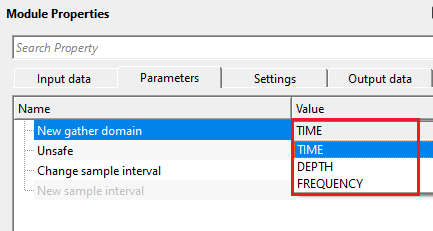
TIME - if the output gather domain should be converted to time then choose this option.
DEPTH - if the output gather domain should be converted to depth then choose this option.
FREQUENCY - this allows the user to change the input domain gather to frequency domain.
Unsafe - when enabled, the module modifies the domain label of the input gather directly, without creating an independent copy of the data. This is faster and uses less memory, but it means both the input and the output of the module point to the same gather object. Use this option only in linear workflows where the original gather is not needed downstream after this step. By default, this option is disabled (Unchecked), which is the safe choice for most workflows.
Caution: enabling Unsafe in a branching workflow where the same input gather is used by more than one downstream module can produce unexpected results, because modifying the shared gather object will affect all branches simultaneously.
Change sample interval - when enabled, lets you override the sample interval of the output gather with a new value. Enable this when the vertical sampling rate stored in the trace headers does not correctly reflect the domain being assigned — for example, when re-labelling a depth gather that was originally sampled in time. By default, this option is disabled (Unchecked), and the sample interval is carried over unchanged from the input gather.
New sample interval — available only when Change sample interval is enabled. Enter the desired sample interval for the output gather. The value is expressed in the natural unit of the target domain: milliseconds (ms) for Time, meters (m) for Depth, and Hz for Frequency. Default: 0.004 (equivalent to 4 ms in time, or 4 m in depth, depending on context). Set this to match the actual vertical sampling of the data so that downstream modules interpret the axis correctly.
Change sample interval - true - this applicable, if the user wants to change the sample interval.
New sample interval - mention the new sample interval value.
![]()
![]()
Auto-connection - By default, TRUE(Checked).It will automatically connects to the next module. To avoid auto-connect, the user should uncheck this option.
Bad data values option { Fix, Notify, Continue } - This is applicable whenever there is a bad value or NaN (Not a Number) in the data. By default, Notify. While testing, it is good to opt as Notify option. Once we understand the root cause of it,
the user can either choose the option Fix or Continue. In this way, the job won't stop/fail during the production.
Notify - It will notify the issue if there are any bad values or NaN. This will halt the workflow execution.
Fix - It will fix the bad values and continue executing the workflow.
Continue - This option will continue the execution of the workflow however if there are any bad values or NaN, it won't fix it.
Number of threads - One less than total no of nodes/threads to execute a job in multi-thread mode. Limit number of threads on main machine.
Skip - By default, FALSE(Unchecked). This option helps to bypass the module from the workflow.
![]()
![]()
Output DataItem
Output gather - the output gather with its domain label updated to the selected target domain (Time, Depth, or Frequency). The sample values themselves are not modified — only the domain metadata tag and, optionally, the sample interval are changed. Connect this output to any downstream module that requires data in the target domain.
Important: this module changes the domain label only. It does not perform any mathematical conversion of sample values — no time-to-depth conversion is computed. Use this module when the data has already been converted (for example, by a migration algorithm) but the metadata has not been updated, or when you need to explicitly declare the domain for a downstream module that checks the domain tag before processing.
The Change domain module runs in multi-threaded mode. The standard execution settings (number of threads, skip, auto-connection, bad value handling) are available in the Settings section and behave identically to other g-Platform sequence modules.
![]()
![]()
In this example workflow, we are reading a velocity model in time and changing the domain from time to depth.


Set up the parameters as per the user/data requirement and execute the module.

![]()
![]()
There are no action items available for this module.
![]()
![]()
YouTube video lesson, click here to open [VIDEO IN PROCESS...]
![]()
![]()
Yilmaz. O., 1987, Seismic data processing: Society of Exploration Geophysicist
 * * * If you have any questions, please send an e-mail to: support@geomage.com * * *
![]()