Merge a few seismic stacks in time domain
![]()
![]()
This module is used to concatenate two seismic datasets in time domain. For example,to make a composite section, to connect fragments cut with different processing parameters in the time domain
![]()
![]()
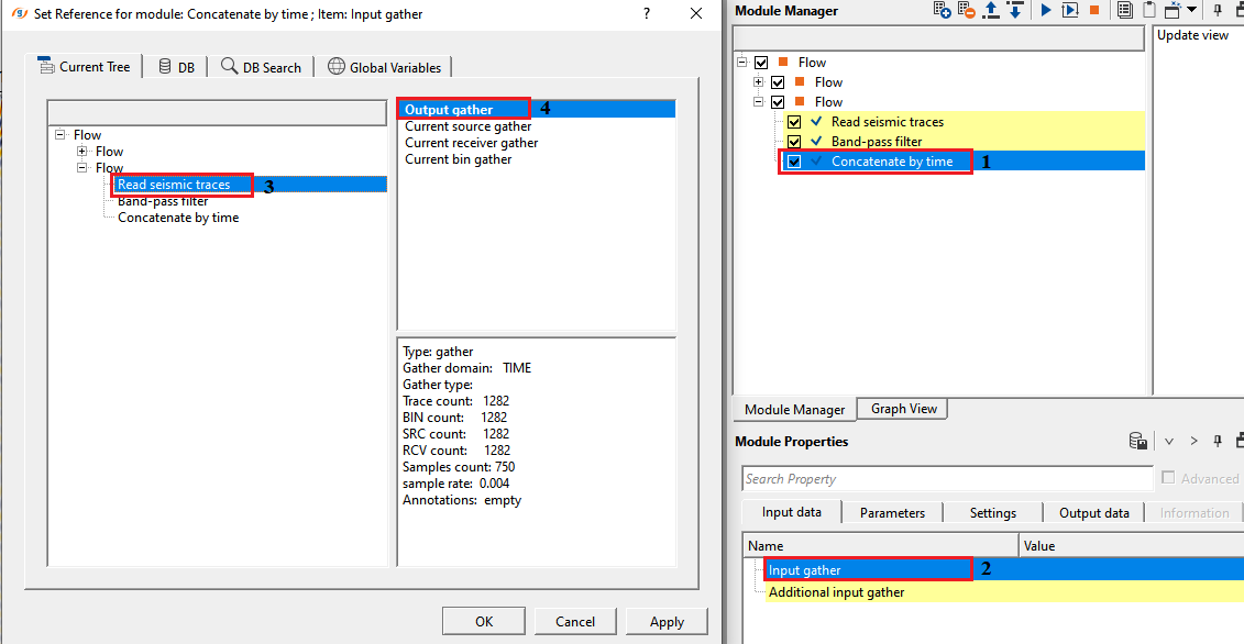
Input gather - connect/reference to one of the seismic section
Connect this input to the first seismic dataset — the one that supplies data above the concatenation boundary. Samples above the specified Time value are taken from this dataset unchanged.
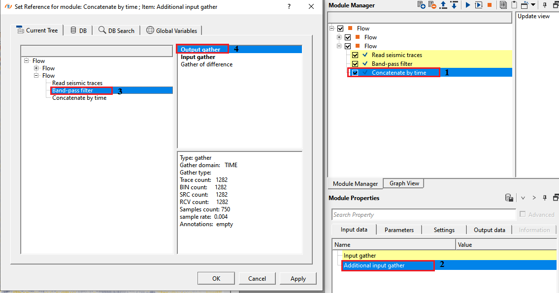
Additional input gather - connect/reference to the other seismic section which needs to be concatenated with input gather.
Connect this input to the second seismic dataset — the one that supplies data below the concatenation boundary. Samples below the specified Time value are taken from this dataset. Both datasets must have identical trace count and sample count.
![]()
![]()
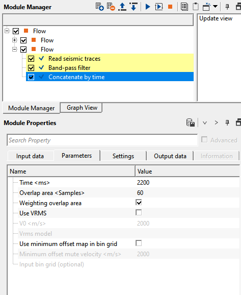
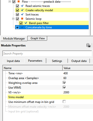
Time - specify the starting merge time in ms. The boundary of concatenated data. The time value where one piece of data ends and joins another
This is the two-way travel time (in milliseconds) at which the module switches from the first dataset to the second dataset. Samples above this boundary are preserved from the Input gather; samples below it are taken from the Additional input gather. The default value is 0 ms. This parameter is available only when Use minimum offset map in bin grid is disabled; when that option is active, the boundary time is derived automatically from the minimum-offset map.
Overlap area - specify the time overlap in terms of samples.
Defines the width of the transition zone around the merge boundary, measured in samples. Within this zone, the module blends samples from both datasets rather than making an abrupt cut. The blend is either a linear taper (when Weighting overlap area is enabled) or a simple average of the two values (when disabled). Set to 0 for a hard cut at the boundary with no blending. Increase this value to smooth a visible amplitude discontinuity at the join.
Weighting overlap area - Average weight of overlapping. Activation of this mode provides a smooth transition from one piece to another
When enabled, the module applies a linear taper across the overlap zone: the contribution of the Input gather decreases linearly from 100% to 0%, while the contribution of the Additional input gather increases from 0% to 100%. This produces a gradual, artifact-free transition. When disabled, the module uses an equal 50/50 average of both datasets across the overlap zone. For best results when the two datasets have significantly different amplitude levels, enable this option and set a generously wide Overlap area.
Use VRMS - by default, FALSE. Velocity information is used in case the input data is Pre-Stack data.
Enable this option when working with pre-stack (offset) gathers. When active, the merge boundary is no longer a flat horizontal line — instead, it follows a hyperbolic moveout curve computed from the Vrms velocity model and the V0 replacement velocity. This ensures that the transition between datasets occurs at the correct subsurface reflection time for each offset, rather than at a fixed two-way time that ignores the offset-dependent traveltime. Disabled by default (flat boundary at the specified Time value).
Use VRMS - true - if the user checks this option, the user must provide the Vrms velocity model along with V0.
Vrms model - connect/reference to the input Vrms model.
Connect a root-mean-square (RMS) velocity model here. The module uses the Vrms value at the merge time and bin location to compute the offset-dependent moveout correction for the concatenation boundary. This input is required when Use VRMS is enabled.
V0 - specify the replacement velocity value.
The near-surface replacement velocity (in m/s) used to compute datum-related time corrections for each trace in pre-stack mode. This value accounts for the elevation difference between the source/receiver datum and the final datum when calculating the moveout-corrected merge boundary. The default value is 2000 m/s. This parameter is only active when Use VRMS is enabled.
Use minimum offset map in bin grid - by default, FALSE. Derives the merge boundary time automatically from a minimum-offset map stored in a bin grid.
When enabled, the concatenation boundary time is computed trace-by-trace from the minimum source-to-receiver offset stored in the attached bin grid, divided by the Minimum offset mute velocity. This spatially varying boundary is useful for mute-consistent concatenation of datasets where the near-surface acquisition geometry changes across the survey. When this option is active, the flat Time parameter is hidden and replaced by the map-derived boundary. Disabled by default.
Minimum offset mute velocity - specify the velocity used to convert minimum offset distance to two-way time.
When Use minimum offset map in bin grid is active, the merge time for each bin is calculated as the minimum offset in that bin divided by this velocity (in m/s). Use a velocity representative of the near-surface direct wave or refraction to reproduce a first-break mute surface. The default value is 2000 m/s.
Input bin grid (optional) - connect/reference to the bin grid that contains the minimum-offset map.
Connect the bin grid that contains the minimum-offset data map. The module reads the minimum-offset value for each bin location from this grid and converts it to a merge boundary time using the Minimum offset mute velocity. This input is required when Use minimum offset map in bin grid is enabled.
![]()
![]()
Number of threads - One less than total no of nodes/threads to execute a job in multi-thread mode. Limit number of threads on main machine.
Controls how many CPU threads the module uses to process traces in parallel. Setting this to the number of available processor cores minus one leaves one core free for the operating system, which keeps the workstation responsive during long jobs. Increase this value to speed up processing on machines with many cores.
Skip - By default, FALSE(Unchecked). This option helps to bypass the module from the workflow.
![]()
![]()
Gather - OUT - generates output gather after concatenation.
The output gather contains the concatenated seismic data. It has the same trace count and total sample count as the two input gathers (both inputs must match in size). Samples above the merge boundary originate from the Input gather; samples below the boundary originate from the Additional input gather; samples in the overlap zone are blended according to the Overlap area and Weighting overlap area settings. Connect this output to the next module in the processing flow, or to a display window to inspect the join immediately.
The Concatenate by time module joins two seismic datasets along a user-defined time boundary, producing a single composite gather. Above the boundary, data is preserved from the first (Input gather) dataset; below the boundary, data is taken from the second (Additional input gather) dataset. An optional overlap zone around the boundary blends the two datasets smoothly to avoid abrupt amplitude jumps.
Typical applications include: building composite stacked sections that combine shallow and deep data processed with different parameters; attaching a refraction-muted shallow zone from one processing flow to a reflection-rich deeper zone from another; or constructing quality-control overlays where one portion of a section has been filtered and the other has not. For pre-stack gathers, the module supports a hyperbolic merge boundary computed from a Vrms velocity model to honour offset-dependent moveout, and a minimum-offset map from a bin grid to reproduce a spatially varying first-break mute surface.
![]()
![]()
In this example, we'll read two datasets. 1st dataset is without band pass filter. 2nd dataset is with band pass filter applied. Now, we want to concatenate both the datasets at certain time.
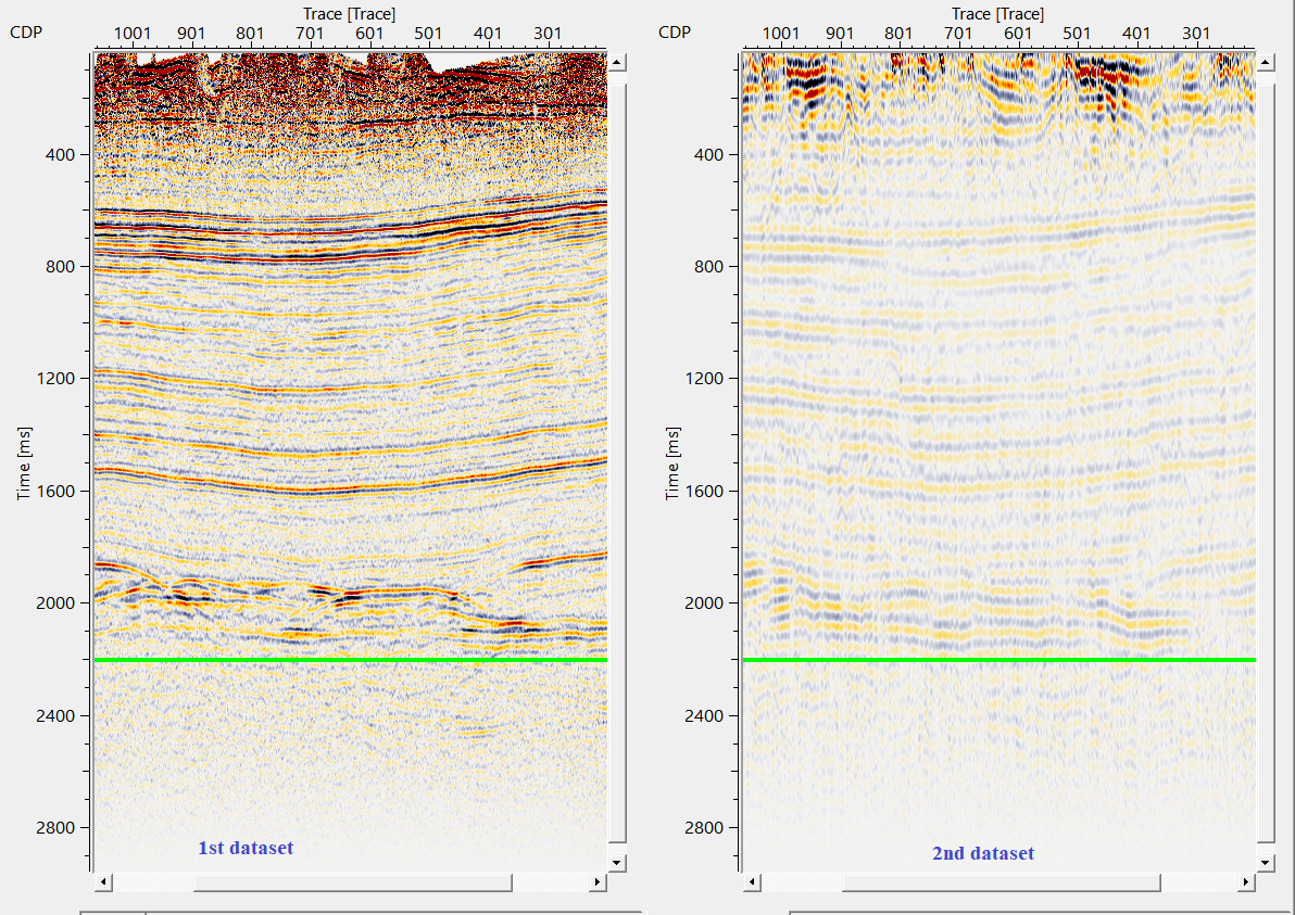
Here, we would like to add data below 2200ms(green line) of the 2nd dataset to 1st dataset with 60ms as taper.

Likewise, the user can prepare for the prestack data also
![]()
![]()
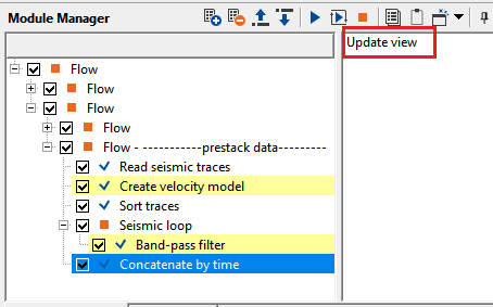
Update view - this action item updates the stack display with merge line displayed on the top of the seismic section. If the user didn't click this option, the merge line (green line) will remain the same.
Click Update view after changing the Time, Overlap area, or velocity parameters to refresh the green merge-line overlay on the seismic display. The merge line shows the exact time position (and, for pre-stack data, the offset-dependent shape) of the concatenation boundary for each trace. Use this visual guide to confirm the boundary is positioned correctly before executing the module.
![]()
![]()
YouTube video lesson, click here to open [VIDEO IN PROCESS...]
![]()
![]()
Yilmaz. O., 1987, Seismic data processing: Society of Exploration Geophysicist
 * * * If you have any questions, please send an e-mail to: support@geomage.com * * *
![]()