Creating sub-surface geometry of 2D seismic data
![]()
![]()
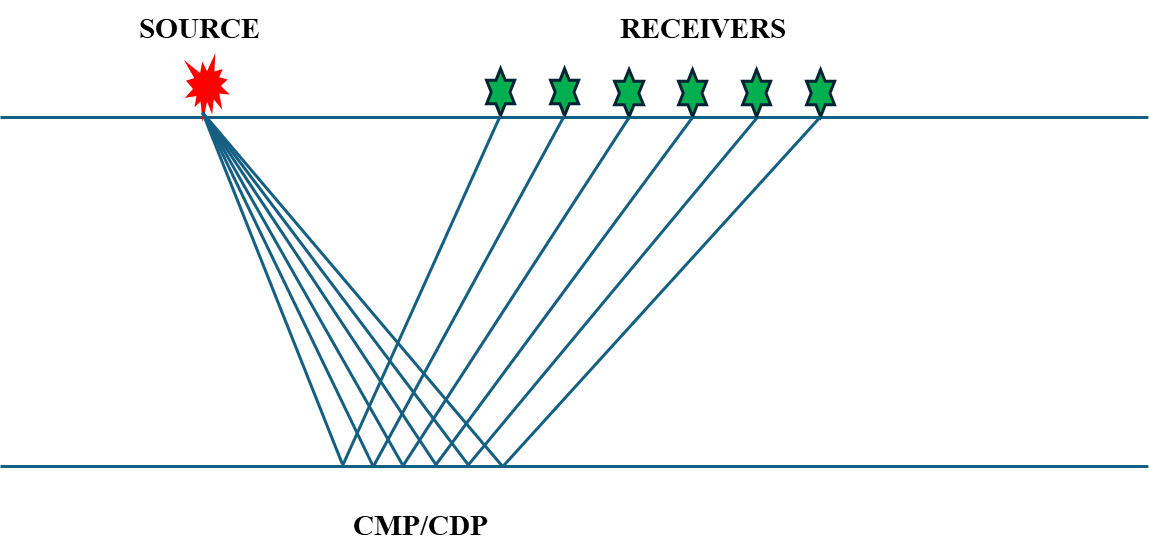
This module creates the sub-surface geometry of 2D seismic data where traces are grouped together by their sub-surface positions into common midpoints (CMP) that are also termed common depth points (CDP). For visual quality control, the module creates several Vista views to QC the 2D binning results.
The binning process consists of the following steps:
1. Filter the midpoints by maximum trace offset value. Only midpoints that have an offset less than or equal to a user specified value will be used.
2. Build the grid. A direct line is drawn from the first source/receiver location to the last source/receiver location. The line is then divided into segments, with each segment being the grid size of the slalom line as defined by the user.
3. Build the slalom line. The set of midpoints are divided into groups using the grid increment previously defined. The center point of each midpoint group is determined,these points are connected and become the slalom line.
4. Smooth the slalom line by using the slalom smooth parameter and the topography smooth window parameter.
5. Build a crooked line using the crooked line increment parameter. The first point of the crooked line is the first source/receiver bin center point and the last point of the crooked line is the last source/receiver center point location.
6. Build a stack line using the stack line step parameter. This is the CDP spacing. The first point of the stack line is the first center point and the last stack point is the last center point. The user assigns the number of the first CDP and these will then increment by one.
7. Filter midpoints with a maximum distance between the MP and CMP point parameter.
There are several options to define binning:
•Create binning – create a sub-surface geometry using parametrization of current module
•Import existing crocked line from ASCII file - it allows to import an existing crooked line from an ASCII file. For example, a crooked line which was built and used by other processing companies/software’s during data processing. The advantage of this option is in using all information of binning from the input file, the parameters of the module in this case are not in use.
The crooked line file in ASCII format should include the following information, 3 columns: CDP number, CDP-X and CDP-Y coordinate of previous result.
The user must verify that the input file has no empty rows or other information except the 3 columns described above.
![]()
![]()
Input DataItem
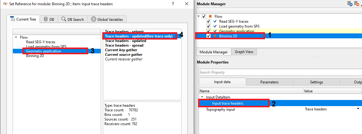
Input trace headers - connect/reference the input trace headers. This can be dependent on the kind of input data we've in the workflow. In case the input data is raw data then we need to provide the Output trace headers of Geometry application module. In case the input data trace headers are already having geometry information, we can simply provide the output trace headers from the "Read SEG-Y traces" module.
Topography input { Trace headers, External map } - Choose the appropriate options to read the elevation/topography information to generate the topography maps and update the trace headers information after binning.
TopographyInput - Trace headers - This options allows the user to connect/reference the input trace headers which already having the source and receiver elevation information.
TopographyInput - External map - This option provides to input any external maps which has topography information.
Topography matrix - This should be referenced to the Topography index. Here we are referencing into Interpolation matrix of "Create interpolation matrix" module. Inside the create interpolation matrix, we've provided source and receiver elevations to create the topography matrix.
![]()
![]()
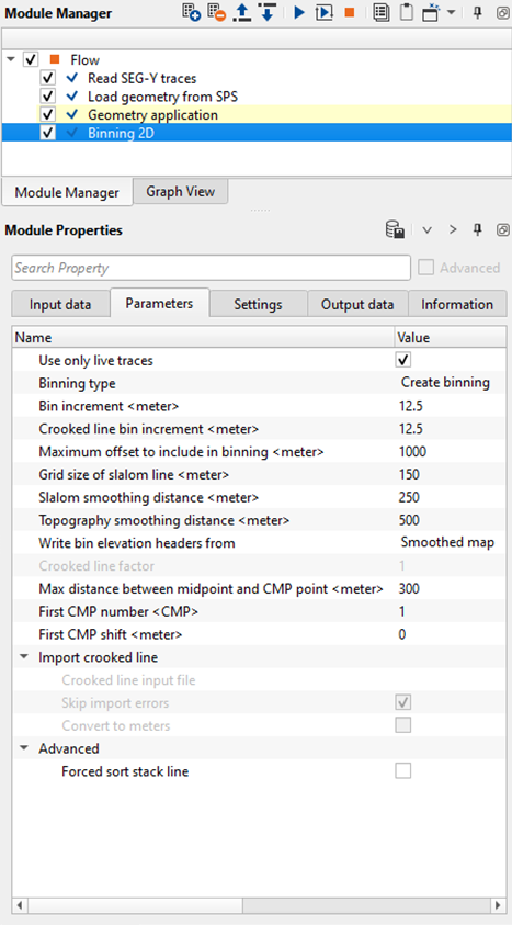
Use only live traces - By default, TRUE (Checked). While doing the binning, it will consider all the live traces (trace_type as 1). Any other trace types will be discarded if this option is checked.
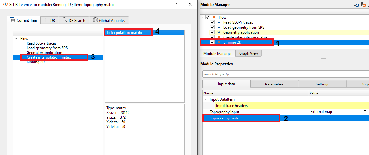
Binning type { Create binning, Simple import binning from txt file } - Choose what options is suitable to the input data. If there is an existing binning information available in an external file then use the "Simple import binning from txt file" option otherwise select "Create binning" option.
Binning Type - Create binning - This options let the user to create a new binning with the user defined binning parameters.
Binning Type - Simple import binning from txt file - This option lets the user to import any existing binning information from an input text file. Browse the path to the input file and provide it.
Bin increment - Distance between (CMP) points of stack line
Crooked line bin increment - Distance between two points of a crooked line
Maximum offset to include in binning - Only midpoints that have an absolute offset distance less or equal to the specified value will be used in the binning process.
Grid size of slalom line - Grid size that is used for slalom line building
Slalom smoothing distance - Smoothing distance over which to smooth the slalom line
Topography smoothing distance - Specify the smoothing distance value to be used to create a smooth topography map. This smoothed topography will be used as a floating datum.
Write bin elevation headers from { Smoothed map, Unsmoothed map } - This parameter allows the user to choose which elevation map information is used to update the CMP/Bin elevation information.
Smoothed map - Used as a floating datum and the elevations are smoothed by a smoothing factor provided by the user
Unsmoothed map - These are the field/original elevations and there is no smoothing applied.
Max distance between midpoint and CMP point - Only midpoints whose distance to the bin center point will be included the bin.
First CMP number - Specify the first CMP number to be considered in the Binning. Let us say 1 or 100 or 1000 etc. (It is recommended that this parameter be 2 times the number of the first live receiver station number. That makes it easier to relate a CMP number to its position relative to the station numbering of the line.)
First CMP shift - This allows the user to adjust the bin grid. If the bin is not at the center of the bin grid and the user wants to change the positioning of the bin grid then specify how much shift it needed for the 1st CMP to make it bin centered. This is a constant shift that will be applicable to the subsequent CMPs.
Import crooked line -
This group of parameters is used when Binning type is set to Simple import binning from txt file. Instead of calculating the crooked line automatically from source and receiver positions, the module reads a pre-existing crooked line definition from an external ASCII text file. This is useful when you want to reuse or reproduce a binning geometry from a previous processing run, or when the acquisition geometry is too irregular for automatic slalom line construction.
Crooked line input file — Path to the ASCII file containing the pre-defined crooked line. The file must contain exactly three columns with no header rows: CDP number, CDP X coordinate, and CDP Y coordinate. Accepted file extensions are .dat, .slalom, and .txt.
Skip import errors — When enabled, the module will continue processing even if some lines in the input file cannot be parsed, skipping over malformed rows rather than stopping with an error. Default: enabled. Disable this option if you need strict validation of the input file.
Convert to meters — Enable this option if the coordinates in the imported crooked line file are in feet and need to be converted to meters for the current project. Default: disabled.
Crooked line input file - Specify the crooked line input file path.
Skip import errors - By default, TRUE(checked). This will skip any errors while importing the crooked line files information.
Convert to meters - By default, FALSE (unchecked). If checked, it will convert the units from feet to meters.
Advanced -
Forced sort stack line — When enabled, the module applies an additional nearest-point sorting pass to the final stack line after all binning is complete. This corrects ordering anomalies that can occur on highly crooked or loop-back acquisition lines where automatic sorting may sequence CDP points incorrectly. Use this option only if you observe CDP numbering reversals or zigzag patterns in the output stack line. Default: disabled.
Forced sort stack line - If checked, this option reverses the stack sorting direction.
![]()
![]()
Auto-connection - By default, TRUE (Checked).
Number of threads - One less than total no of nodes/threads to execute a job in multi-thread mode.
Skip - By default, FALSE(Unchecked). This option helps to bypass the module from the workflow.
![]()
![]()
Output DataItem
Output trace headers - This generates the final updated traces headers with all the bin information which includes the CMPs, CMP elevation, inline, cross line numbers etc.
Output gather - This updates the output gather trace headers.
Output stack line - This updates the stack line headers information.
Output crooked line - This generates the crooked line headers information.
Output bin grid - This modules allows the user to save the output bin grid for future requirements. This can be saved as an item by using "Save item" module.
Topography matrix out - This will outputs the topography information. This can be used for where the topography matrix is required like we generated the Interpolation matrix by using the "Create interpolation matrix". Same way, we can use this information and connect/reference to any other module which requires the topography matrix.

Trace collection bins count - This provides the information about the total number of bins after the binning.
Stack line bins count - Provides the total number of bins in the stack line.
Imported line bin step - Provides the bin step size from the imported crooked line.
Stack line length - Provides the total stack line length in Km.
Number of input traces - Total number of input traces participated in the binning.
Number of output traces - Total number of output traces after the binning.
Number of missed traces - Total number of traces falling outside the bin grid. This information is used for QC purpose to check that all the output traces after binning are inside the bin grid. If any traces are missing outside the bin grid, change the Max distance from the mid point to CMP parameter.
![]()
![]()
In this example, we are using Poland 2D seismic data and the corresponding Navigation data. We are reading both the seismic and navigation using the respective modules followed by assigning the geometry using "Geometry application" module. Taking the geometry assigned output trace headers information as an input to the Binning 2D module and do the binning. This Binning 2D module, generates the CMP/CDP information along with their corresponding CDP X & Y coordinates.
After executing the Binning 2D module, generate the Vista items and go through the Location map information. There are many vista items are stacked up on each other. Uncheck the each option and understand each one of them. For your reference, we are showing some of those vista items
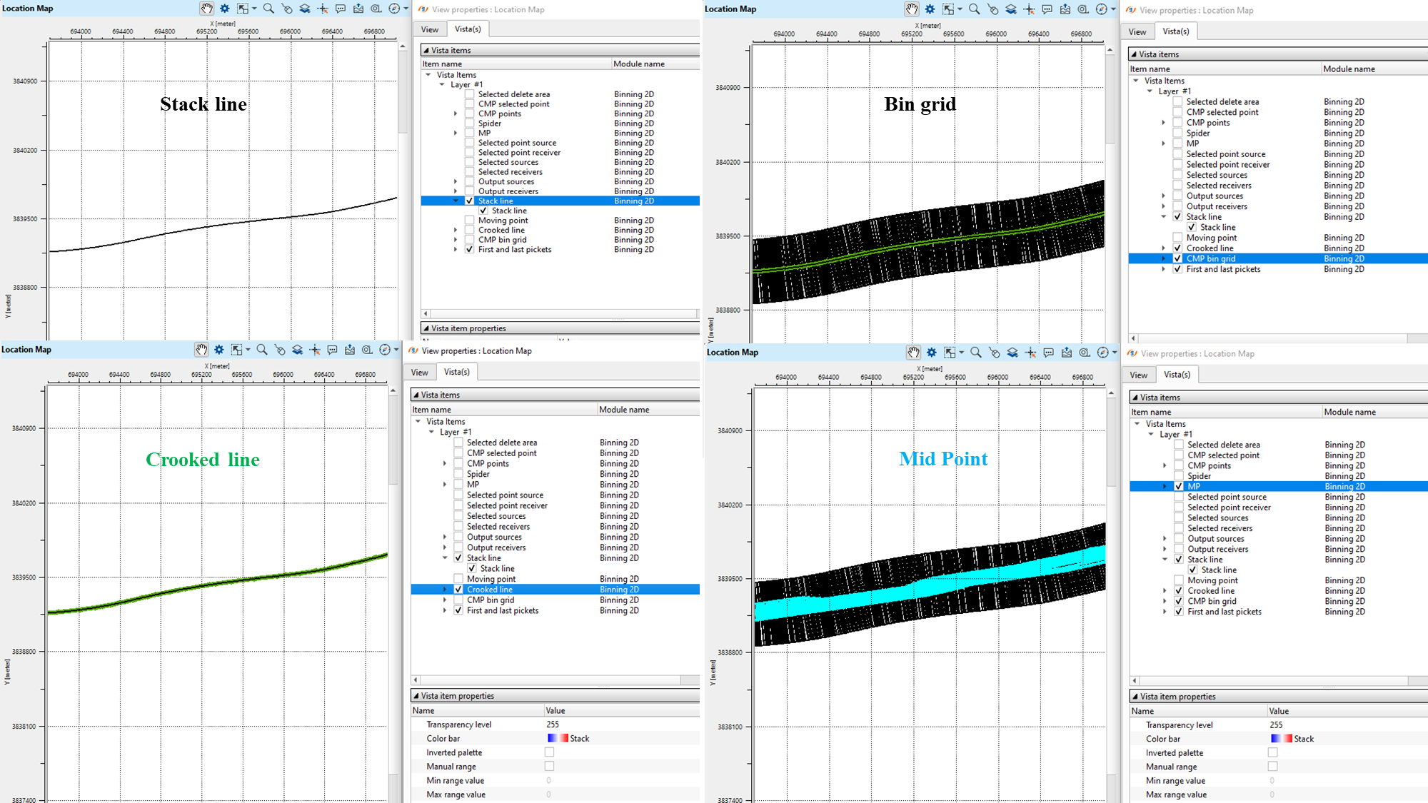
Binning 2D module also generates the Topography map, Fold map, Minimum and Maximum offset maps etc.
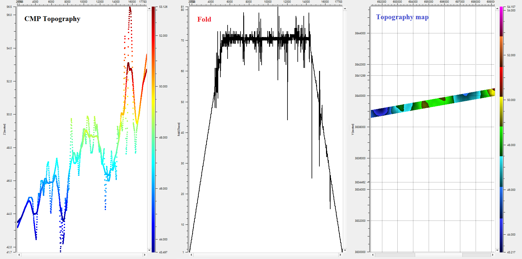
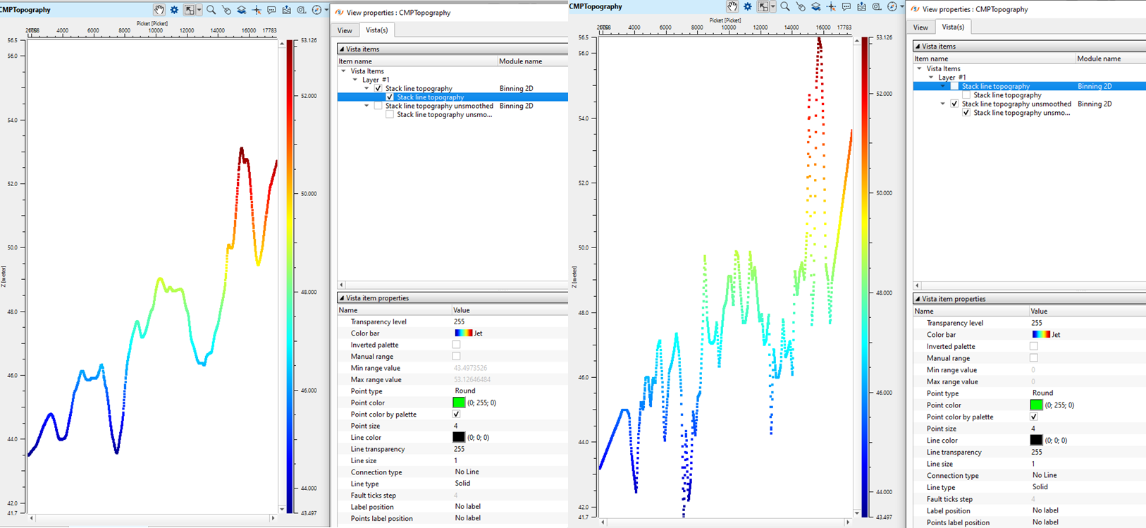
In the CMP topography map, we see two plots overlaid. One is the smoothed cmp topography and the other one is unsmoothed cmp topography. The smoothed cmp topography is used as a floating datum.
One of the key parameter of the Binning 2D is Max distance between Mid point and CMP. Let's change this value from existing 300 m to 100 m and see how the location map changes as well the information tab. As we mentioned earlier, that the information tab provides all the statistics about the sail line.
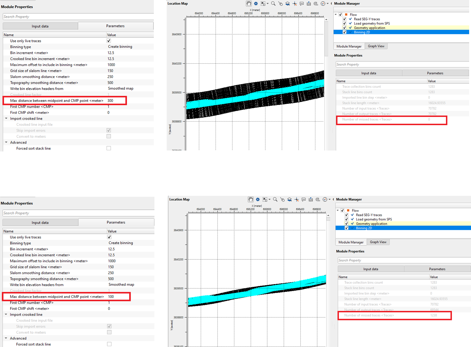
From the above image, we see that the there are no missing traces with a Max distance between midpoint and CMP point is 300m however when this is changed from 300 to 100 m, there are 1238 traces are missing or falling outside the bin grid. This way the user can check the right parameters for the Binning 2D module and avoid any missing information.
![]()
![]()
There are no action items are available so the user can ignore it
![]()
![]()
YouTube video lesson, click here to open [VIDEO IN PROCESS...]
![]()
![]()
Yilmaz. O., 1987, Seismic data processing: Society of Exploration Geophysicist
 * * * If you have any questions, please send an e-mail to: support@geomage.com * * *