Converting coordinates from one CRS to another CRS
![]()
![]()
Coordinate conversion means transforming a point from one coordinate system (CRS) to another.
Two types:
1.Transformation (datum change, e.g., WGS84 → Indian 1954)
2.Projection (lat/lon → grid in meters, e.g., WGS84 → UTM)
Often both happen together.
What is CRS (Coordinate Reference System)?
A CRS defines how locations on Earth are described.
A CRS specifies:
•What shape of Earth you are using (datum/ellipsoid)
•How coordinates are measured (lat/lon, meters, etc.)
•What projection (if any) is used
•The area of validity
Types of CRS:
✔ Geographic CRS
•Uses latitude & longitude
•Units: degrees
•Example: EPSG:4326 (WGS84)
✔ Projected CRS
•Uses X, Y coordinates in meters
•Derived using a map projection
•Example: EPSG:32643 (WGS84 / UTM Zone 43N)
✔ Vertical CRS
•Heights: ellipsoidal or orthometric
•Example: EGM96 geoid height
In simple words, CRS = How you define and measure positions on Earth.
EPSG stands for European Petroleum Survey Group, now maintained by the OGP / IOGP Surveying & Positioning Committee.
EPSG maintains the world’s official database of:
•Coordinate Reference Systems (CRS)
•Map projections
•Datums
•Transformation methods
•Geoid models
Each CRS in the database has a unique EPSG code. For all EPSG codes, visit https://www.epsg.io
What is EPSG:4326?
It is ....
•WGS84 datum
•Latitude & Longitude in degrees
•Ellipsoidal coordinate system
•Used by GPS, Google Earth, mobile phones, etc.
What is PROJ4?
Proj4 (now simply called PROJ) is an open-source library used worldwide for:
•Map projections
•Datum transformations
•Coordinate conversions
•CRS (Coordinate Reference System) definitions
In simple words:
Proj4 is the mathematical engine that converts coordinates from one CRS to another.
It is the core behind many GIS and geospatial tools.
Proj4 string is a compact text-based formula that defines a coordinate system or map projection for PROJ, GIS tools, and geospatial workflows.
What is Datum?
A datum is the mathematical model of Earth used by a CRS.
A datum defines:
•The origin point
•The ellipsoid dimensions (size, shape of Earth)
•Orientation in 3D space
There are two main types:
✔ Geodetic Datum (for lat/lon)
Defines the shape of Earth:
•WGS84 (global)
•NAD83 (North America)
•Everest 1830 (India)
•GDA2020 (Australia)
✔ Vertical Datum (for heights)
Defines sea level:
•Mean Sea Level (MSL)
•EGM96
If two datums differ, coordinates differ even if projection is same.
Example:
•WGS84 vs Indian 1954 coordinates may differ by 100–300 m at same physical point.
What is Projection?
A map projection converts Earth’s curved surface (lat/lon) into a flat grid (X,Y).
All projections introduce distortion in:
•Area
•Shape
•Distance
•Direction
Common projections:
•UTM (Universal Transverse Mercator) → very common for engineering & seismic
•Mercator → web maps
•Lambert Conformal Conic → aviation weather
•Albers Equal Area → climate maps
Projection = Mathematical method to flatten the Earth.
How They Relate?
Think of it as a hierarchy:
DATUM → defines Earth's shape
↓
CRS → uses the datum, and may use a projection
↓
PROJECTION → converts lat/lon into X,Y (meters)
Example:
WGS84 (datum)
↓
EPSG:4326 (CRS, geographic, lat/lon)
↓
EPSG:32643 (CRS, projected using UTM zone 43N)
•CRS → the complete definition of how coordinates are expressed.
•Datum → the shape and size of Earth used for coordinates.
•Projection → the math that converts curved Earth (lat/lon) into flat maps (meters).
![]()
![]()
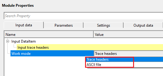
Input DataItem - connect/reference to Input DataItem usually Read seismic traces/Read SEG-Y traces modules Output DataItem. In case the user wants to use the work mode as trace headers then connect/reference to Output trace headers of the corresponding module.
Work mode { Trace headers, ASCII file } - select the type of input to be considered for. By default, Trace headers.
This parameter controls what source of coordinate data the module will process. Choose Trace headers to convert the X, Y, and Z coordinates stored in seismic trace headers (source, receiver, and bin positions). This is the standard mode when the module is connected in a seismic processing flow. Choose ASCII file to convert coordinates listed in a text file, which is useful when working with standalone geometry tables, well location lists, or any tabular data file that contains X/Y columns in a source CRS that must be re-expressed in a target CRS. The output converted file is written automatically alongside the input file with the suffix _out appended to the file name.
Work mode - Trace headers - TRUE (Checked) then connect/reference to Output trace headers of the corresponding module.
Input trace headers - connect/reference to Output trace headers of the corresponding module.
Work mode - ASCII file - TRUE (Checked) then provide the input ASCII file with all the information
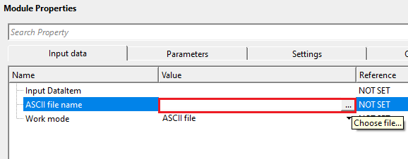
ASCII file name - provide the ASCII file name
Browse to and select the input text file containing the coordinates to be converted. The file must be a plain-text format with the extension .txt or .ascii, with columns delimited by tabs, spaces, semicolons, or commas. After conversion, the module writes a new output file to the same folder as the input, using the same base name with _out appended before the extension (for example, coords_out.txt). Header rows above the Start row are copied unchanged to the output file.
Start row - specify the starting row of the input ASCII file to extract the correct information
Specifies the row number (1-based) at which coordinate data begins. All rows before this number are treated as header lines and are copied verbatim to the output file without coordinate conversion. Set this to 1 if the file contains no header. Set it to 2 or higher to skip label rows. For example, if your file has a single column-header row followed by data, set Start row to 2. Default: 1.
X column - specify X-coordinates column range
Enter the column number (1-based) that contains the X coordinate (easting or longitude) in the input file. The converted X value is written back to this same column in the output file. This field must be set to 1 or greater — the module will report an error if it remains at 0. Default: 0 (must be set by the user).
Y column - specify Y-coordinates column range
Enter the column number (1-based) that contains the Y coordinate (northing or latitude) in the input file. The converted Y value is written back to this same column in the output file. This field must be set to 1 or greater. Default: 0 (must be set by the user).
Z column - specify Elevation/Z column range
Enter the column number (1-based) that contains the elevation or Z value in the input file. This field is only required when Convert elevation is enabled. If Convert elevation is unchecked, this field is ignored and the Z column in the output file is left unchanged from the input. When Convert elevation is checked and Z column is left at 0, the module will report an error. Default: 0.
Decimals - if there are any decimal values of Z column, mention the decimal places.
Sets the number of decimal places used when writing the converted X, Y, and Z coordinate values to the output file. For projected coordinates expressed in meters (such as UTM), 1 or 2 decimal places is typically sufficient. For geographic coordinates in decimal degrees (such as WGS84 latitude/longitude), use a higher value such as 6 or 7 to preserve the required positional precision. Default: 1.
![]()
![]()
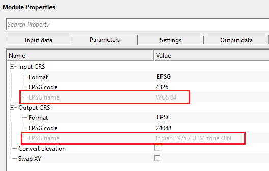
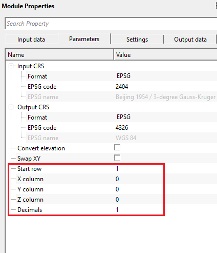
Input CRS - this source/input data CRS coordinates.
Defines the coordinate reference system of the input data — that is, the CRS in which the source X, Y coordinates are currently expressed. The module offers two sub-parameters to specify this CRS:
Format — select how the input CRS will be specified: either by EPSG code or by a Proj4 string. Default: EPSG. Use EPSG when you have a standard code (e.g., 4326 for WGS84 geographic, 32643 for UTM Zone 43N). Use Proj4 when working with a non-standard or custom projection definition.
EPSG code — enter the numeric EPSG code that identifies the input CRS. Default: 4326 (WGS84 geographic latitude/longitude). After you enter a valid code, the read-only EPSG name field is populated automatically so you can verify the code corresponds to the expected coordinate system. Look up codes at https://www.epsg.io.
Proj4 string — visible only when Format is set to Proj4. Enter the full PROJ projection string that describes the input coordinate system (e.g., +proj=utm +zone=43 +datum=WGS84). This field accepts any valid PROJ library definition string.
Format { EPSG, Proj4 } - By default, EPSG. This is the WGS84 coordinate system
Format - EPSG -
EPSG code - provide the EPSG code. By default, 4326.
EPSG name - it displays the name for code 4326 as WGS84 for easy understanding.
Format - Proj4 - Proj4 is the mathematical engine that converts coordinates from one CRS to another.
Proj4 string - provide Proj4 string name. For example "+proj=longlat +datum=WGS84 +no_defs"
Output CRS - this is the target/output CRS that the user wants the final coordinates
Defines the coordinate reference system into which the coordinates will be converted. After processing, all output coordinates will be expressed in this CRS. The same Format/EPSG code/Proj4 string sub-parameters are available as for the Input CRS (see above). Default EPSG code: 4326. For example, if your seismic data was acquired using local survey coordinates referenced to a regional datum and you need to deliver results in WGS84 UTM, set the Input CRS to the original survey projection and the Output CRS to the target UTM zone EPSG code. The underlying transformation is performed by the PROJ coordinate transformation library using the proj.db coordinate system database.
Format { EPSG, Proj4 }
Format - EPSG -
EPSG code - specify the target/output EPSG code. For example, EPSG 23947 (Indian 1954 UTM Zone 47N)
EPSG name - it displays the name for code 23947 as Indian 1954 datum UTM Zone 47N for easy understanding.
Format - Proj4 - Proj4 is the mathematical engine that converts coordinates from one CRS to another.
Proj4 string - provide Proj4 string name. For example "+proj=longlat +datum=WGS84 +no_defs"
Convert elevation - this allows the user to convert the elevations also along with the coordinates. By default, FALSE (Unchecked).
When checked, the Z coordinate (elevation or depth value) is also transformed in addition to the horizontal X and Y positions. This is relevant when converting between CRS definitions that include a vertical component — for example, changing from ellipsoidal heights to orthometric (geoid-referenced) heights. Leave unchecked if your CRS transformation only affects horizontal positioning. When using ASCII file mode, enabling this option requires that the Z column index is also specified. Default: unchecked.
Swap XY - this check box allows the user to swap the coordinates. By default, FALSE (Unchecked).
When checked, the X and Y output coordinates are swapped after conversion. Some coordinate systems and data formats store coordinates in Y, X (northing, easting) order rather than the conventional X, Y (easting, northing) order. Enable this option when the downstream software or file format expects coordinates in the opposite axis order. This swap is applied as a post-processing step after the CRS transformation. Default: unchecked.
![]()
![]()
Auto-connection - By default, TRUE(Checked).It will automatically connects to the next module. To avoid auto-connect, the user should uncheck this option.
When enabled, the output of this module is automatically passed as input to the next module in the processing flow. Disable this option if you want to insert a manual step between modules or if you need to inspect the converted data before further processing.
Number of threads - One less than total no of nodes/threads to execute a job in multi-thread mode. Limit number of threads on main machine.
Controls how many CPU threads are used when processing in multi-threaded mode. Set this to a value lower than the total number of available threads on your machine to leave capacity for other processes. For most coordinate conversion tasks the computation is fast and the default value is sufficient.
Skip - By default, FALSE(Unchecked). This option helps to bypass the module from the workflow.
When checked, this module is bypassed and its input data is passed through unchanged to the next module in the flow. Use this option to temporarily disable coordinate conversion without removing the module from your workflow, for example when testing the flow with data that is already in the correct CRS. Default: unchecked.
![]()
![]()
Output DataItem - generates coordinate converted output data items. Output trace headers will have converted coordinates.
The output seismic data with all trace header coordinate fields (source X/Y, receiver X/Y, and bin X/Y) replaced by their transformed equivalents in the target CRS. The seismic amplitudes and all non-coordinate header fields are preserved without modification. Connect this output to downstream modules that require data in the target coordinate system.
This module has no custom action buttons. All processing is configured through the parameter panel and executed as part of the standard workflow.
![]()
![]()
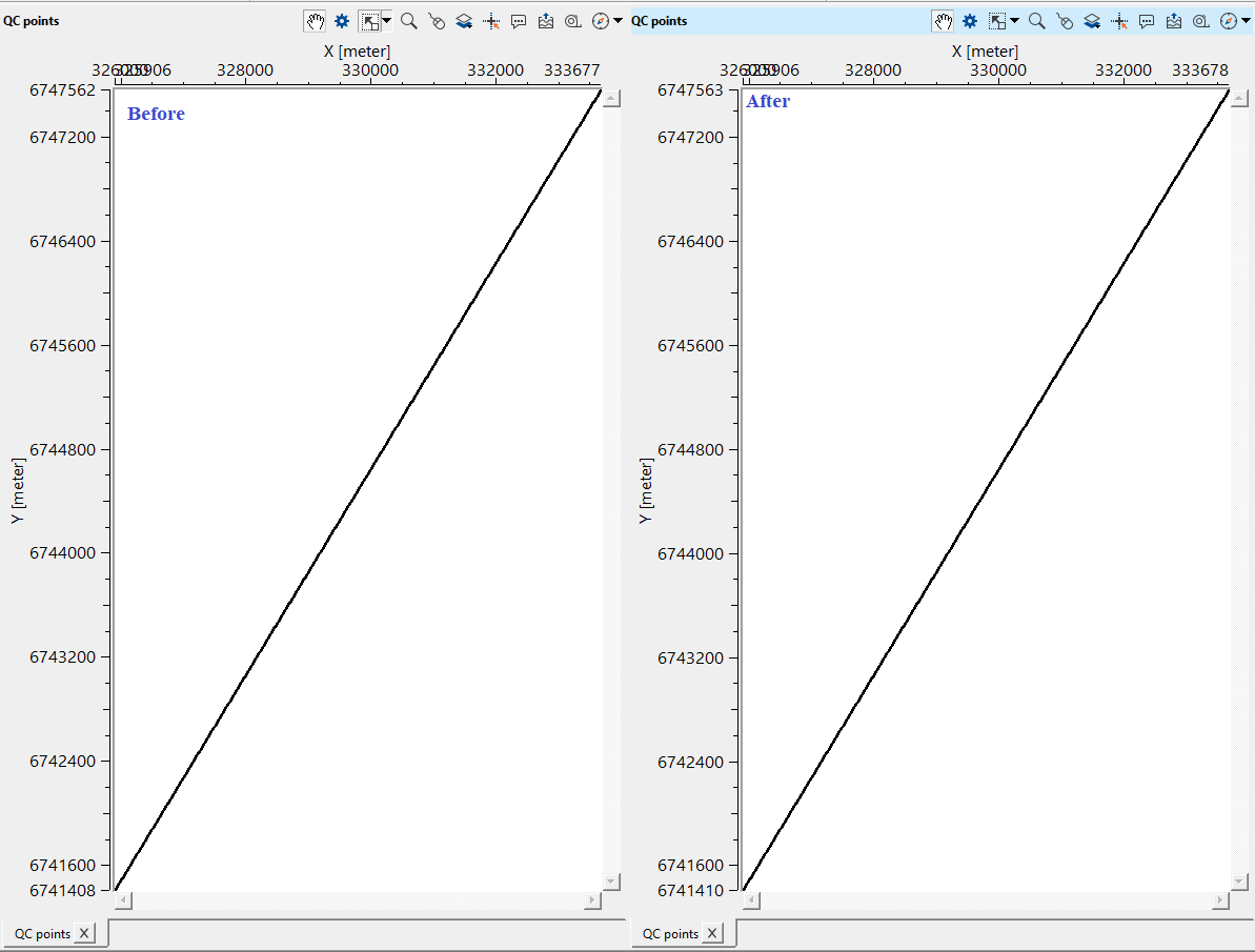
In this example, we convert one CRS to another CRS. There won't be any Vista items available for this module. To QC, the user can use "QC trace geometry" module to verify the conversion.
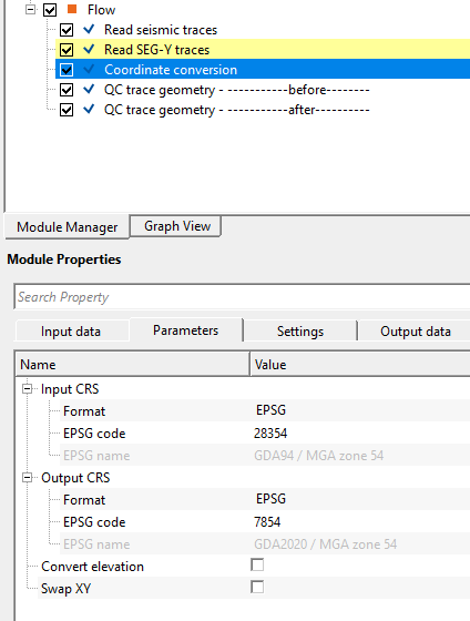
In the input CRS, we've GDA94 datum and we would like to convert to GDA2020. So, we've provided the Input and Output EPSG codes and executed the module. It will convert all the x,y coordinates from GDA94 to GDA2020.
![]()
![]()
There are no action items available for this module.
![]()
![]()
YouTube video lesson, click here to open [VIDEO IN PROCESS...]
![]()
![]()
Yilmaz. O., 1987, Seismic data processing: Society of Exploration Geophysicist
 * * * If you have any questions, please send an e-mail to: support@geomage.com * * *
![]()