Description
Imaging - 2D CO-MF generates seismic stack sections from the results of a 2D Common Offset MultiFocusing (CO-MF) search. The module reads the CO-MF search database, selects events for a specified offset class, applies MultiFocusing time corrections to align reflections, and stacks them into a coherent seismic image. It is the final imaging step in the 2D CO-MF workflow, following the Engine - 2D CO-MF search procedure.
In addition to the stacked section, this module can produce a range of parameter attribute sections derived from the MultiFocusing analysis: semblance correlation, emergence angle, wavefront curvature radii (CRE, CEE), stacking velocities, dip, and fold. These attributes support velocity model building, AVO analysis, and structural interpretation. The module also provides interactive visualization panels for angle and velocity semblance gathers, a map view of picked and calculated bins, and tools for picking velocity and angle corridors.
Use this module after completing the 2D CO-MF engine search to transform search results into interpretable seismic sections and parameter volumes. Results can be exported to SEG-Y format using the built-in Export params to sgy action.
Input data
Storage file 2D-CO
The 2D CO-MF search database file (extension .kdb) produced by the Engine - 2D CO-MF procedure. This file contains the MultiFocusing parameters and semblance results for every analyzed common-offset bin along the 2D line. The imaging module reads these stored events and uses them to construct the output stack and parameter sections. This field is mandatory — the module cannot run without a valid CO-MF storage file.
GMFPickingItem
An optional link to a velocity and angle constraint picking object from another procedure. When connected, the picking corridors defined in the linked item constrain which MultiFocusing events are accepted during imaging — only events falling within the picked velocity and angle ranges are included in the stack. This allows the interpreter to guide the imaging using manually defined velocity constraints, improving the quality of the stack in areas with complex or multivalued moveout.
Parameters
Calc Offset
The source-receiver offset class (in meters) for which the CO-MF stack section will be created. The CO-MF search database stores results for multiple offset classes; this parameter selects which offset class to image. Set to -1 (the default) to image all available offset classes together. Specify a positive offset value in meters to produce a section for a single offset class. This is useful when you need to examine moveout behavior or amplitude variation at a specific source-receiver distance.
Create NMO corrected gathers
When enabled, applies a MultiFocusing moveout correction to shift each event to its zero-offset time before stacking, producing NMO-corrected output gathers in addition to the stack section. This is equivalent to applying a time correction based on the CO-MF traveltime parameters so that reflections appear at their zero-offset two-way travel times. Enable this option when you need output gathers suitable for AVO analysis or further processing that requires NMO-corrected traces. Default: false.
Image creation parameters
This group of parameters controls how MultiFocusing events stored in the search database are selected and combined into the final stack. Image creation is a stacking procedure in which time-corrected events corresponding to optimal MultiFocusing parameters are summed. The number of events preserved during the search is determined in Parametrization – MF engine → Wave values → Maximum number of directions. Each event stored in the database has the following properties:
•Semblance value
•Time
•Indexes corresponding to the MF parameter space (velocity, angle)
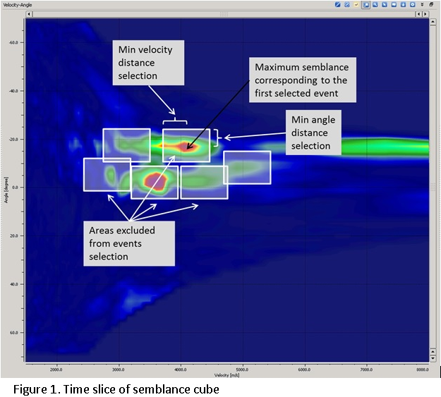
During stacking, different criteria can be applied to select which events participate: by angle range, by velocity range, or by semblance distribution.
Directions
The maximum number of events (directions) from the MultiFocusing search to include in the stack at each time sample. Increasing this value allows more events to be summed, which can improve the stack when multiple reflections or diffractions are present at the same time. However, including too many low-quality events may degrade signal-to-noise ratio. Default: 1. Valid range: 1 to the Maximum Number of Directions set during the search.
From angle
The lower bound of the emergence angle range (in degrees) used to filter events during stacking. Only events whose MultiFocusing emergence angle is greater than or equal to this value will be included in the summation. Use this to exclude steeply dipping events or specific structural elements from the stack. Default: -90°. Valid range: -90 to 0.
To angle
The upper bound of the emergence angle range (in degrees) used to filter events during stacking. Only events whose MultiFocusing emergence angle is less than or equal to this value will be included in the summation. Together with From angle, this defines the angular aperture of the stack. Default: 90°. Valid range: 0 to 90.
SN Enhance
When enabled, normalizes the data by the semblance value before stacking, which acts as a signal-to-noise enhancement filter. Events with higher semblance (stronger coherence) contribute proportionally more to the final stack. This option is useful in areas with low signal-to-noise ratio where conventional stacking may produce noisy results. Default: false.
Correlation threshold
The minimum semblance value (expressed as a percentage of the local maximum semblance) that an event must exceed in order to be included in the summation. Events with semblance below this threshold are treated as noise and excluded from the stack. Increasing this value produces a cleaner stack by rejecting low-coherence events, but may reduce fold in areas with complex geology. Default: 10%. Valid range: 10–90%.
Min angle distance selection
The minimum separation (in semblance grid cells along the angle axis) required between two events before they can both be selected for summation. This prevents closely spaced events in the angle domain from being double-counted, allowing events that represent distinctly different emergence angles to be separated and stacked independently. Increase this value when you observe merging of events with similar angles. Default: 1 grid cell. Valid range: 1–100.
Min radius distance selection
The minimum separation (in semblance grid cells along the velocity axis) required between two events before they can both be selected for summation. This ensures that events with distinctly different stacking velocities are treated as separate reflections rather than being merged into a single event. Use a larger value when multiple events with similar velocities need to be resolved. Default: 100 grid cells. Valid range: 1–100.
Testing
This group of parameters controls the spatial search and interpolation tolerances used during the CO-MF imaging calculation. These parameters affect how the module matches CO-MF search results to the actual trace positions and how it interpolates between known events.
Max Distance To MF CMP
The maximum allowable distance (in meters) between an output CMP position and the nearest CO-MF analysis point. If no CO-MF result is found within this radius around a CMP, that CMP will not contribute to the stack. Reducing this value enforces stricter spatial matching between the search results and the output grid, while increasing it allows interpolation over larger gaps in the CO-MF coverage. Default: 50 m. Valid range: 0–2000 m.
Max Distance To MF CO Trace
The maximum allowable distance (in meters) between an input seismic trace and the nearest CO-MF common-offset trace stored in the search database. This parameter controls how broadly the module searches for matching CO-MF traces when applying the time correction to real seismic data. A larger value allows more distant traces to be used, which can help in areas with sparse data, while a smaller value enforces tighter matching. Default: 1000 m. Valid range: 0–100000 m.
Interpolation Window Length
The time window (in milliseconds) used when interpolating MultiFocusing parameters between stored database points along the time axis. A longer window produces smoother spatial interpolation of the CO-MF parameters but may blur rapid vertical changes in the wavefront geometry. A shorter window preserves sharper parameter variations but may introduce interpolation artefacts. Default: 10 ms.
Stabilisation Window Length
The time window (in milliseconds) used to stabilize the interpolated MultiFocusing parameters before applying them during imaging. This smoothing step suppresses erratic parameter jumps caused by noise in the semblance surface, leading to a more geologically consistent stack. A larger window produces more stable but spatially averaged parameters, while a smaller window follows local variations more closely. Default: 10 ms.
Visualization
This group controls display-only transformations applied to the stack section and velocity semblance panels. The settings in this group affect only what is shown in the interactive visualization — they do not modify the output data written to disk.
Datum
The elevation (in meters) of the flat final datum to which the seismic data will be shifted for visualization. This value is used together with the ShiftToDatum option. Set this to the desired reference datum elevation. Default: 0 m.
ShiftToDatum
When enabled, shifts the displayed seismic section and semblance panels to the flat datum elevation defined by the Datum parameter. This is a visualization aid that compensates for surface topography in the display, making it easier to correlate events across the line. The shift is applied for display only and does not alter the output stack. Default: false.
VelocityAGC
The time window length (in seconds) for automatic gain control applied to the velocity semblance and angle semblance panels in the interactive display. AGC normalizes the semblance amplitude within this sliding window to equalize the display across different time depths, making it easier to pick velocity trends in both shallow and deep sections. This setting affects the visualization panels only; it does not change the output stack or stored parameters. Default: 0.6 seconds.
Types
This group of toggle switches controls which output attribute sections are created during imaging. For each enabled attribute, both a visualization panel and a gather output are generated. Enable only the attributes you need, as each additional output increases processing time and disk usage.
Stack
When enabled, creates the main zero-offset MultiFocusing stack section — the primary output of this module. This section is produced by summing all selected events after applying the CO-MF time correction. It represents the best-focus image of the subsurface for the chosen offset class. Default: true.
Correlation
When enabled, creates a semblance (correlation) attribute section showing the coherence of stacked events across the line. High values indicate strong constructive interference of the MultiFocusing-corrected traces, corresponding to well-resolved reflectors. This section is useful for quality control of the imaging result and for identifying zones of poor data quality or complex geology. Default: false.
Angle
When enabled, creates a section showing the MultiFocusing emergence angle — the angle (in degrees) at which the wavefront arrives at the surface for each stacked event. The emergence angle is related to the apparent dip of reflectors and can be used for dip-angle analysis, structural interpretation, and as input to dip-corrected processing steps. Default: false.
Gamma
When enabled, creates a section showing the MultiFocusing Gamma parameter, which represents the ratio between the NIP (Normal Incidence Point) wavefront radius and the Normal wavefront radius. Gamma is related to the inhomogeneity of the subsurface velocity field and can be used as a structural and lithological indicator. Default: false.
CRE
When enabled, creates a section showing the CRE (Common Reflection Element) radius, the radius of curvature of the NIP wavefront. The CRE radius is a fundamental MultiFocusing attribute related to the depth of the reflector and the overburden velocity. It is used in velocity model building and can be related to the interval velocity through appropriate inversion. Default: false.
CRE2
When enabled, creates a section showing the squared CRE radius (CRE²). This variant of the CRE attribute is useful for certain velocity inversion algorithms that work in the squared-radius domain. Default: false.
CRE Azimuth
When enabled, creates a section showing the azimuth direction of the CRE wavefront curvature. In 2D acquisition this is typically perpendicular to the line direction, but the attribute is provided for completeness and for workflows that use 3D-consistent azimuth information. Default: false.
CEE
When enabled, creates a section showing the CEE (Common Emerging Element) radius, the radius of curvature of the Normal wavefront. The CEE radius describes the large-scale wavefront curvature and, together with the CRE radius, fully characterizes the MultiFocusing traveltime approximation. It is used in velocity analysis and can be related to the zero-offset NMO velocity. Default: false.
CEE2
When enabled, creates a section showing the squared CEE radius (CEE²). This variant is used in velocity inversion workflows that operate in the squared-radius domain. Default: false.
CEE Azimuth
When enabled, creates a section showing the azimuth direction of the CEE wavefront curvature. Default: false.
V Slow
When enabled, creates a section showing the slow (minimum) stacking velocity from the CO-MF parameterization. The slow velocity corresponds to the NIP wavefront curvature direction and is useful for anisotropy analysis and for identifying velocity anomalies associated with lithological boundaries. Default: false.
V Fast
When enabled, creates a section showing the fast (maximum) stacking velocity from the CO-MF parameterization. Together with V Slow, this attribute describes the azimuthal velocity variation and can be used to derive the principal stacking velocities in dipping or anisotropic media. Default: false.
Dip
When enabled, creates a section showing the reflector dip angle (in degrees) derived from the MultiFocusing emergence angle. This dip attribute can be used directly for structural interpretation or as input to dip-guided processing steps. Default: false.
Azimuth Dip
When enabled, creates a section showing the azimuth of the dip direction. In 2D surveys, this attribute indicates the direction of maximum dip relative to the acquisition line. Default: false.
VSlow / cos(Dip)
When enabled, creates a section showing the dip-corrected slow velocity: V Slow divided by the cosine of the dip angle. This quantity approximates the true zero-dip stacking velocity and is useful for converting the CO-MF stacking velocity into an interval velocity estimate, particularly in dipping layer situations. Default: false.
VFast / cos(Dip)
When enabled, creates a section showing the dip-corrected fast velocity: V Fast divided by the cosine of the dip angle. This dip-corrected attribute is useful for deriving true stacking velocities in the presence of structural dip. Default: false.
Fold
When enabled, creates a section showing the MultiFocusing stack fold — the number of events summed at each time sample along the line. The fold section is a useful quality control tool: areas with low fold indicate sparse data coverage or poor MF search convergence, while uniformly high fold indicates good coverage. Default: false.
Export Params
This group of parameters controls the format and behavior of the CO-MF parameter export to SEG-Y. The export is triggered by the Export params to sgy custom action.
Write mode
Controls how the exported CO-MF parameter SEG-Y file is written. In Direct mode, the existing file is overwritten with a fresh export. In Append mode, the exported data is added to the end of an existing file, allowing results from multiple runs to be accumulated into a single output. Use Append mode when exporting results in segments or across multiple imaging runs. Default: Direct.
Convert To Feet
When enabled, converts all exported distance and velocity measurements from metric units (meters, m/s) to imperial units (feet, ft/s) in the output SEG-Y file. Enable this option when working in a project that uses imperial units or when the output will be loaded into software expecting feet. Default: false (metric units).
No Zero Values For Velocity
When enabled, replaces samples in the velocity parameter sections that have zero velocity values with the surface velocity V₀ instead. Zero-velocity samples occur at locations where the CO-MF search did not converge or where no valid event was found. Filling these gaps with V₀ prevents downstream applications from misinterpreting zero values as actual velocity data. Default: false.
Zero padded
When enabled, traces at bins with zero fold (locations where no CO-MF calculation was performed) are filled with zero-amplitude samples and written to the output SEG-Y file, preserving the full spatial geometry of the output. When disabled, such empty traces are omitted from the output file, producing a smaller file but with gaps in the spatial coverage. Enable this option when downstream applications require a complete, regularly sampled output volume with no missing trace positions. Default: false.