Description
The Imaging - 2D ZO-MF module is the final imaging step in the 2D Zero-Offset MultiFocusing (ZO-MF) workflow. It reads the MF search results stored in the database and produces a Zero-Offset (ZO) MultiFocusing stacked section together with a full suite of derived MF parameter sections such as stacking velocity, emergence angle, gamma, CRE and CEE radii, dip, and fold.
During imaging the module applies a velocity corridor constraint: instead of picking a single velocity function, the interpreter defines a velocity window (corridor) within which optimal MF parameters are selected automatically per time sample. Events outside the corridor are excluded from the stack. Corridor interpolation between picked locations reduces the risk of velocity-picking errors compared to conventional CMP velocity analysis.
The module offers interactive views for location map, semblance cube projections (angle gather and velocity gather), and the resulting image stack. Velocity corridor and angle corridor can be picked interactively. Custom actions allow clearing, loading, and saving the picking session, and exporting MF parameters to SEG-Y.
Input data
Storage file
Path to the 2D ZO-MF search results database file (KDB format, extension .kdb). This file is produced by the Engine - 2D ZO-MF module and contains the multi-dimensional semblance cube along with all stored wave events. Select the database that corresponds to the survey line you intend to image.
Mute picking
An optional mute function (3D picking item) applied before stacking. When connected, samples above the mute curve are zeroed on each trace prior to summation. Use this input to suppress shallow noise or first-break energy that would otherwise contaminate the ZO stack.
MF picking file
File path for the saved velocity corridor picking session. This field is managed automatically by the Save picking and Load picking custom actions. Saving preserves the velocity and angle corridor picks so they can be reloaded in a later session without repeating the interactive analysis.
Parameters
Image creation parameters
Image creation is a stacking procedure of time-corrected events corresponding to the optimal MF parameters. The number of events preserved during the MF Search is determined in Parametrization – MF engine → Wave values → Maximum number of directions. Each event stored in the database has the following properties: semblance value, zero-offset time, and indexes corresponding to the MF parameter grid (angle, velocity radius). During stacking, different selection criteria can be applied: by angle range, by velocity corridor, or by semblance threshold.
Directions — Maximum number of wave events (semblance peaks) to include in the stack per time sample and per CMP location. Set to 1 to use only the strongest event. Increase this value to stack multiple reflectors arriving at the same time, such as in areas of complex geology or conflicting dips. Must not exceed the Maximum Number of Directions set during the MF Search. Default: 1.
From angle — Lower bound of the emergence angle range (in degrees) used to filter events before stacking. Events with an emergence angle below this value are excluded. Use negative values to include events dipping in the opposite direction. Range: −90 to 0. Default: −90.
To angle — Upper bound of the emergence angle range (in degrees). Events with an emergence angle above this value are excluded. Together with From angle, this pair defines an angle gate that can be used to reject steeply dipping noise or to generate dip-limited partial stacks. Range: 0 to 90. Default: 90.
SN Enhance — When enabled, traces are weighted by their semblance value before summation (semblance-weighted stack). This enhances the signal-to-noise ratio of the final stack by emphasizing high-coherence events and suppressing low-coherence noise. Use this option when the data quality is variable across the aperture. Default: false (unweighted stack).
Correlation threshold — Minimum semblance value (expressed as a percentage of the maximum semblance in the search) required for an event to participate in the stack. Events below this threshold are discarded. Increasing this value enforces stricter coherence and can reduce noise contributions, but may also exclude legitimate weak reflectors. Range: 10–90%. Default: 10.
Min angle distance selection — Minimum separation (in semblance grid cells along the angle axis) between any two events selected for summation at the same time sample. This prevents closely spaced semblance peaks — which may represent the same physical event — from being double-counted. Increase this value when the angle grid is dense or when spurious duplicate events appear in the output. Range: 1–100. Default: 1.
Min radius distance selection — Minimum separation (in semblance grid cells along the velocity/radius axis) between events selected for summation. Works analogously to Min angle distance selection but along the velocity dimension. Use this parameter to separate events with similar angles but different stacking velocities. Range: 1–100. Default: 100.
Testing
This parameter group contains advanced options that control how the module locates and aligns traces during imaging. These settings are primarily used for quality-control and testing purposes.
Use trace headers
When enabled, the module uses recorded trace header coordinates to match input traces to their corresponding MF CMP locations. When disabled, trace matching is performed using the geometry database only. Enable this option if trace headers have been correctly populated and you want to verify that coordinates in the data are consistent with the MF grid. Default: true.
Max distance to MF CMP
Maximum allowed distance (in metres) between a trace header coordinate and the nearest MF CMP bin centre for the trace to be accepted. Traces further than this threshold from any MF CMP are excluded from the imaging. Increase this value only if the survey geometry is irregular and some traces fall outside nominal bin boundaries. Range: 0–2000 m. Default: 50 m.
Interpolation window length
Half-length of the time window (in seconds) used to interpolate the MF time-shift when moving a trace sample to its corrected zero-offset time. Larger values produce smoother corrections across adjacent samples at the cost of reduced time resolution. Range: 0–1000 s. Default: 0.010 s (10 ms).
Stabilization window length
Half-length of the stabilization time window (in seconds) applied to smooth abrupt transitions in the MF time-correction field between neighbouring samples. This reduces trace-stretching artefacts at events boundaries. Range: 0–1000 s. Default: 0.010 s (10 ms).
Shift Type
Selects the method used to apply the MF time correction to each trace sample. Three options are available:
Shift use windows — applies the shift using short time windows throughout the trace (default, most robust).
Shift use stretching — applies the shift by continuously stretching/squeezing the trace, analogous to NMO stretching.
Shift use windows only on extremes — applies windowed shifts only at the top and bottom of the trace, using stretching in between.
Visualization
This group controls display options applied to sections and velocity semblance panels for interactive visualization only. These settings do not affect the output data written to disk.
Datum
Elevation of the flat (final) datum used for the visualization shift, in metres. When Shift to datum is enabled, traces are displayed with a static time shift that removes the effect of surface topography and places all traces as if recorded at this datum level. Default: 0 m.
Shift to datum
Enable to shift the displayed section to the flat datum defined above. This is a visualization-only correction; it does not alter the output stack. Useful when comparing the MF stack against conventional CMP stacks that have already been referenced to a flat datum. Default: false.
Velocity AGC
Length of the time window (in seconds) used to apply Automatic Gain Control (AGC) to the semblance panels displayed in the velocity analysis view. A shorter window enhances fine time detail; a longer window provides a more stable amplitude background. This parameter only affects on-screen display of the semblance gather, not the picking or the stack. Default: 0.6 s.
Polygon picking params
This group defines constraints for a velocity-constrain polygon applied to the MF parameter space. A polygon drawn in the velocity-vs-time display restricts which MF events are accepted for a given CMP location. All parameters in this group apply to the currently selected polygon.
PolygonId
Integer identifier of the polygon constraint currently being edited. Multiple polygons can be defined to apply different velocity or angle constraints to different CMP ranges. Selecting a polygon ID loads its associated velocity and angle limits into the fields below. Range: 0–99. Default: 0.
MinVelocity
Lower bound of the stacking velocity corridor (in m/s) for the selected polygon area. Events with a stacking velocity below this value are excluded from the stack within the polygon. Set this to the expected minimum geologically reasonable stacking velocity for the target interval. Default: 0 m/s.
MaxVelocity
Upper bound of the stacking velocity corridor (in m/s) for the selected polygon area. Events with a stacking velocity above this value are excluded. Together with MinVelocity this defines the velocity gate that selects the best-fitting MF parameters inside the polygon. Default: 0 m/s (no upper limit).
UseAngle
Enable to activate the angle constraint for the selected polygon. When enabled, only events with an emergence angle between MinAngle and MaxAngle are accepted within the polygon. Use this when you need to separate conflicting dips within a specific velocity range. Default: false.
Clear Angle Inside Area
When enabled, events whose emergence angle falls inside the defined MinAngle–MaxAngle range are excluded from the stack within the polygon (inverse angle gate). This is the complement of UseAngle: instead of keeping events inside the angle window, it rejects them. Useful for surgical suppression of a specific dip component. Default: false.
MinAngle
Minimum emergence angle (in degrees) for the polygon angle constraint. Active only when UseAngle is enabled. Range: −90 to 90 degrees. Default: 0.
MaxAngle
Maximum emergence angle (in degrees) for the polygon angle constraint. Active only when UseAngle is enabled. Range: −90 to 90 degrees. Default: 0.
UseGamma
Enable to activate the gamma constraint for the selected polygon. Gamma is the MF wavefront parameter related to the radius of the normal-incidence point (NIP) wavefront curvature. When enabled, only events with gamma within the MinGamma–MaxGamma range participate in the stack inside the polygon. Default: false.
MinGamma
Minimum gamma value (in degrees) for the polygon gamma constraint. Active only when UseGamma is enabled. Range: −90 to 90 degrees. Default: 0.
MaxGamma
Maximum gamma value (in degrees) for the polygon gamma constraint. Active only when UseGamma is enabled. Range: −90 to 90 degrees. Default: 0.
Types
This group selects which MF attribute sections are computed and made available for visualization and export. Each enabled attribute creates both an interactive display panel and an output gather that can be connected to a downstream export module. Enable only the attributes you need to reduce computation time.
Stack
Create the zero-offset MultiFocusing stack section. This is the primary imaging output: each sample is the coherency-weighted sum of time-corrected input traces using the optimal MF parameters at that time and location. This output is the MF equivalent of a CMP stack. Default: true.
Create the MF semblance (correlation) section. Each sample contains the maximum semblance value of the selected event. This section can be used as a confidence map: high-semblance areas indicate where the MF parameters are well-constrained and the stack is most reliable. Default: false.
Angle
Create the MF emergence angle section. Each sample contains the emergence angle (in degrees) of the selected event at that time and CMP location. This attribute represents the local reflector dip as seen from the surface and is useful for structural interpretation and dip-azimuth analysis. Default: false.
Gamma
Create the MF gamma section. Gamma is a wavefront attribute related to the curvature of the normal-incidence point (NIP) wavefront, providing information about the subsurface reflector geometry. Default: false.
CRE
Create the MF Common Reflection Element (CRE) radius section. The CRE radius describes the radius of curvature of the NIP wavefront, which is related to the depth of the reflector under the normal-incidence point. This attribute supports subsequent PSDM model building. Default: false.
CRE2
Create the MF secondary CRE radius section (CRE2). This is an additional wavefront curvature attribute derived from the MF parameterization. Default: false.
CRE Azimuth
Create the azimuth of the CRE wavefront. Represents the directional orientation of the NIP wavefront curvature, useful in 3D-extended 2D surveys. Default: false.
CEE
Create the MF Common Evolution Element (CEE) radius section. The CEE radius describes the curvature of the normal wavefront, related to the radius of curvature of the reflector itself. Together with CRE it provides the two independent MF curvature parameters. Default: false.
CEE2
Create the MF secondary CEE radius section (CEE2). An additional normal-wavefront curvature attribute. Default: false.
CEE Azimuth
Create the azimuth of the CEE wavefront. Represents the directional orientation of the normal wavefront curvature. Default: false.
V Slow
Create the MF VRMS-MF (V Slow) section. This velocity attribute corresponds to the smaller principal stacking velocity of the MF operator and is directly related to the zero-offset stacking velocity. It is the key velocity attribute for depth conversion and velocity model building. Default: false.
V Fast
Create the MF V Fast section. This is the larger principal stacking velocity of the MF operator, associated with the along-dip direction. Together with V Slow it characterizes the full 2D velocity field of the MF traveltime surface. Default: false.
Dip
Create the MF reflector dip section. Each sample contains the local dip angle of the reflector derived from the MF emergence angle. This section can be used directly for structural interpretation or as input to dip-guided processing steps. Default: false.
Azimuth Dip
Create the azimuth of the reflector dip vector. Provides the horizontal direction of the maximum dip, complementing the Dip magnitude section. Default: false.
VSlow / cos(Dip)
Create an approximation of the conventional CMP stacking velocity, computed as V Slow divided by the cosine of the reflector dip angle. This expression converts the dip-corrected MF velocity into a quantity directly comparable to NMO velocities picked during CMP velocity analysis, facilitating cross-validation between MF and CMP processing results. Default: false.
VFast / cos(Dip)
Create the dip-corrected V Fast section (V Fast divided by cos(Dip)). Analogous to VSlow/cos(Dip) but derived from the faster principal velocity. Default: false.
Fold
Create the MF fold section. Each sample contains the number of input traces that contributed to the stack at that time and CMP location after applying all selection criteria (velocity corridor, angle constraint, semblance threshold). Low fold values indicate areas where the constraints excluded most events or where the input coverage is sparse. Default: false.
Export params
This group controls options for exporting the computed MF attribute sections to SEG-Y files via the Export params to sgy custom action.
Write mode
Controls how the exported SEG-Y file is written. Direct overwrites any existing output file. Append adds new traces to an existing file, useful for exporting results from multiple survey lines into a single SEG-Y dataset. Default: Direct.
Convert to feet
When enabled, velocity and distance attribute values in the output SEG-Y are converted from the internal metric system (m/s, m) to the imperial system (ft/s, ft). Enable this option when delivering results to projects that use feet-based coordinate and depth references. Default: false.
No zero values for velocity
When enabled, samples in velocity attribute sections that have a zero value (indicating no valid MF event was selected) are filled with the near-surface velocity V0 from the MF model instead of zero. This avoids artefacts in downstream processes such as interval velocity computation that cannot handle zero stacking velocities. Default: false.
Zero padded
When enabled, CMP locations where the fold is zero (no events were selected) are included in the output SEG-Y as all-zero traces. This preserves the trace geometry of the output, which may be required by interpretation software that expects a fixed number of traces per line. When disabled, zero-fold traces are omitted, resulting in a smaller output file. Default: false.
Shift to datum
When enabled, the exported SEG-Y sections are shifted to the flat datum defined below, applying a static time correction that removes topographic effects from the data on disk (as opposed to the visualization-only datum shift in the Visualization group). Default: false.
Datum
Elevation of the flat datum (in metres) used for the export datum shift. Active only when Shift to datum (Export) is enabled. Set this to match the project datum used for all other processing steps to ensure consistent time references across the output SEG-Y files. Default: 0 m.
Band-pass
This group defines a trapezoidal band-pass filter that can be applied to the output stack before display and export. The filter is defined by four corner frequencies forming a cosine-tapered pass-band.
Use
Enable or disable the band-pass filter. When enabled, the four frequency corner parameters below become active and the filter is applied to the output. Use the band-pass to suppress low-frequency noise (ground roll residuals) or high-frequency noise before final QC or export. Default: false.
Frequency 1
Low-cut start frequency of the band-pass filter (in Hz). Frequencies below this value are completely attenuated. The taper begins at this frequency. Typical values are 1–5 Hz to remove very low-frequency noise. Default: 1 Hz.
Frequency 2
Low-cut end frequency of the band-pass filter (in Hz). Frequencies above this value and below Frequency 3 are passed without attenuation. This frequency marks the end of the low-frequency taper. Default: 5 Hz.
Frequency 3
High-cut start frequency of the band-pass filter (in Hz). Frequencies above this value begin to be attenuated. This should be set below the Nyquist frequency and above the dominant signal content. Default: 100 Hz.
Frequency 4
High-cut end frequency of the band-pass filter (in Hz). Frequencies above this value are completely attenuated. Must not exceed the Nyquist frequency for the data sample rate. Default: 105 Hz.
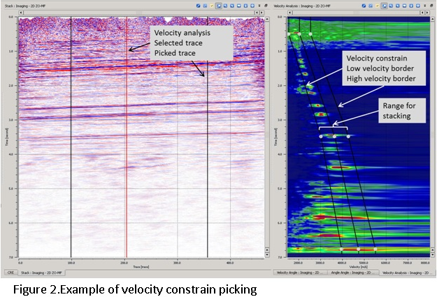
Velocity analysis view
Unlike conventional CMP processing, the MF method produces a multi-dimensional semblance cube that makes direct velocity picking too complex. For this reason, velocity picking in MF is replaced by picking a velocity corridor (constraint): the optimal MF parameters within the corridor are selected automatically. Only events located inside the velocity constraint are used for stacking. Between two picked corridor locations, the velocity constraint is interpolated; this interpolation of the velocity corridor reduces the risk of picking errors compared to point-by-point velocity function interpolation during conventional CMP velocity analysis.
The interactive display provides three synchronized panels: the velocity semblance gather (projection of the semblance cube along the velocity axis, showing time vs. stacking velocity), the angle semblance gather (projection along the angle axis, showing time vs. emergence angle), and the image stack (current ZO section). Velocity and angle corridors can be picked interactively in their respective panels and applied immediately to update the stack.