Seismic gather interpolation
Interpolation and/or extrapolation of seismic gather
Theory
Seismic Gather Interpolation is the process of estimating and inserting missing traces within a seismic gather (shot, CMP, receiver, or offset gather) to achieve regular spatial sampling. Interpolation improves spatial continuity, enhances signal coherence, and prepares data for downstream processes such as velocity analysis, migration, stacking, and inversion.
Typical causes of missing or irregular traces include:
- Obstructed receiver locations
- Equipment failure
- Sparse acquisition geometry
- Intentional decimation for acquisition efficiency
Interpolation aims to reconstruct the wavefield in a physically consistent manner while minimizing artifacts and noise amplification.
Objectives of gather interpolation
- Restore uniform trace spacing
- Improve FK and Radon domain resolution
- Reduce spatial aliasing
- Enhance semblance and velocity picking
- Improve migration and imaging quality
- Enable regularized processing workflows
Input / Output
Input
- Seismic gather (CMP, shot, receiver, or offset domain)
- Irregular or sparse spatial sampling
- Optional velocity or dip information
Output
- Regularly sampled gather
- Interpolated traces inserted at missing spatial locations
- Preserved amplitudes and phase characteristics
Interpolation workflow
- Geometry analysis and detection of missing traces
- Domain transformation
- Signal model estimation
- Trace reconstruction
- Inverse transform (if applicable)
- Quality control and residual analysis
Input data
Input DataItem
Input gather
this input gather could be anything like shot/receiver/cmp gather. Connect/reference to Output gather.
Parameters
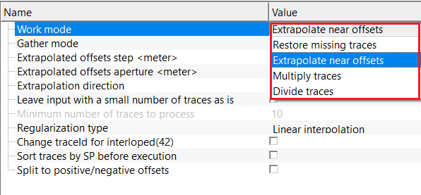
Work mode { Restore missing traces, Extrapolate near offsets, Multiply traces, Divide traces }
there are multiple work mode options available. Depending on the work mode, the parameter set changes along with the Regularization type. By default, Multiply traces.
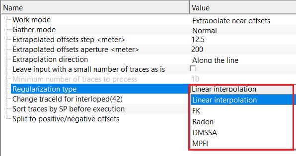
Regularization type { Linear interpolation, FK, Radon, DMSSA, MPFI }
there are various regularization types are available. Each regularization scheme has its merits and demerits. Depending on the user requirements, choose the respective regularization scheme from the drop down menu. By default, Linear Interpolation.
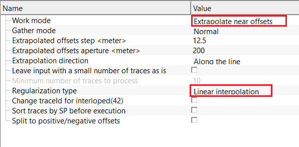
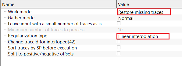
Regularization type - Linear interpolation
reconstructs missing traces by linearly interpolating between neighboring traces in the space–time domain. Fast and stable for small gaps, but does not account for dip or curvature of seismic events and is not recommended for large gaps or complex geology.
Change traceId for interloped(42)
by default, FALSE(Unchecked). This option allows the user to easily identify the interpolated traces by flagging the TRACE_TYPE marked as 42.
Sort traces by SP before execution
by default, FALSE(Unchecked). This allows the user to sort the input traces in common Shot Point domain before execution. Pay attention this option, as it may slow down the process.
Split to positive/negative offsets
by default, FALSE(Unchecked). This option splits the input data into positive and negative offsets in case the input gather is a split spread configuration.
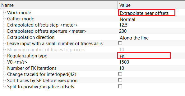
Regularization type - FK
uses frequency–wave number (FK) domain regularization to reconstruct missing traces by enforcing lateral coherence in the FK domain.
V0
reference velocity used to estimate dip limits in the FK domain and separate physical signal energy from spatially aliased components. By default, 1500 m/sec.
Number of FK iterations
number of iterative FK reconstruction cycles. Higher values improve convergence and interpolation quality but increase execution/running time. By default, 10.
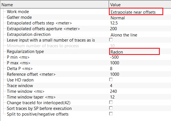
Regularization type - Radon
uses Radon-domain regularization to reconstruct missing traces based on moveout consistency of seismic events.
Trace window
number of neighboring traces used to estimate the Radon model. Larger windows improve stability but reduce local adaptivity.
Time window
time range used for Radon analysis and reconstruction. Restricting the window improves resolution and stability.
Time window taper
applies a smooth taper at the edges of the time window to reduce boundary artifacts and ringing.
P min
minimum moveout or curvature parameter in Radon space, typically corresponding to the highest expected subsurface velocity. By default, -500 ms.
P max
maximum moveout or curvature parameter in Radon space, typically corresponding to the lowest expected subsurface velocity. By default, 1000 ms.
Delta P
sampling interval of the Radon parameter axis. Smaller values improve resolution but increase computational cost. By default, 8 ms.
Reference offset
offset used as a reference during Radon reconstruction, controlling how events are aligned across offsets. By default, 1000 m.
Use HD radon
enables high-definition Radon transform with improved resolution and reduced energy leakage. By default, FALSE(Unchecked).
Use HD radon - true
if it is TRUE (Checked), activates high-definition Radon processing. Recommended for sparse or irregular data.
Number of radon iterations - number of iterative Radon inversion cycles. Increasing iterations improves reconstruction accuracy.
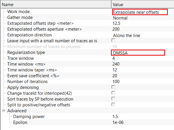
Regularization type - DMSSA
uses Data-driven Multichannel Singular Spectrum Analysis (DMSSA) to reconstruct missing traces by enforcing low-rank structure.
Trace window
number of adjacent traces used for multichannel embedding. Controls spatial coherence of reconstruction. By default, 50.
Time window
time window length used to construct the Hankel matrix. Longer windows capture extended events but increase computation. By default, 250 ms.
Time window taper
applies tapering at the time window edges to improve numerical stability and reduce boundary effects. By default, 50 ms.
Event save coefficient
controls the amount of coherent signal energy preserved during reconstruction. Lower values increase noise suppression. By default, 20%.
Number of iterations
number of DMSSA reconstruction cycles. Higher values improve convergence for large gaps or sparse data. By default, 100.
Apply denoising
enables additional noise attenuation during DMSSA reconstruction. Recommended for low signal-to-noise data. By default, FALSE(Unchecked).
Advanced
expands advanced DMSSA controls for fine-tuning stability and convergence behavior.
Damping power
controls the strength of damping applied to singular values. Higher values increase smoothing and noise suppression. By default, 1.5
Epsilon
small stability constant used to prevent numerical instability during matrix inversion. Increasing this value improves robustness. By default, 1e-06 (10-06 ).
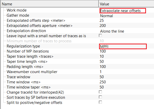
Regularization type - MPFI
uses Matching Pursuit Fourier Interpolation (MPFI) to reconstruct missing traces using sparse spectral representation.
Trace window
number of neighboring traces used for sparse spectral modeling. Larger windows improve frequency estimation. By default, 50.
Time window
time range used for sparse Fourier decomposition and reconstruction. By default, 250 ms.
Time window taper
applies tapering at time window boundaries to reduce spectral leakage and improve continuity. By default, 50 ms.
Number of MP iterations
number of matching pursuit iterations used to build the sparse model. Higher values improve accuracy but increases run time. By default, 100.
Taper trace length
applies tapering along the spatial direction to reduce edge artifacts and improve lateral continuity. By default, 10.
Taper time length
applies tapering along the time direction to smooth window boundaries and reduce ringing. By default, 50 ms.
Padding length
adds zero-padding in time and/or space before transformation to improve spectral resolution and numerical stability. By default, 100 ms.
Wavenumber count multiplier
scales the number of wavenumber samples used during reconstruction. Higher values improve spatial resolution at increased cost. By default, 0.
Work mode - Restore missing traces
reconstructs missing or irregularly sampled traces in the gather using interpolation or extrapolation methods. This mode restores spatial continuity and regular sampling without modifying existing valid traces. Use for trace dropouts, sparse acquisition, or irregular geometry.
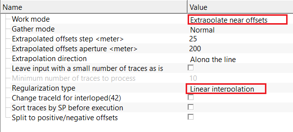
Work mode - Extrapolate near offsets
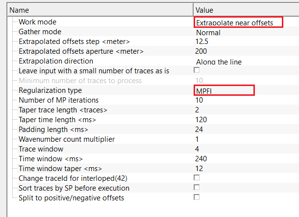
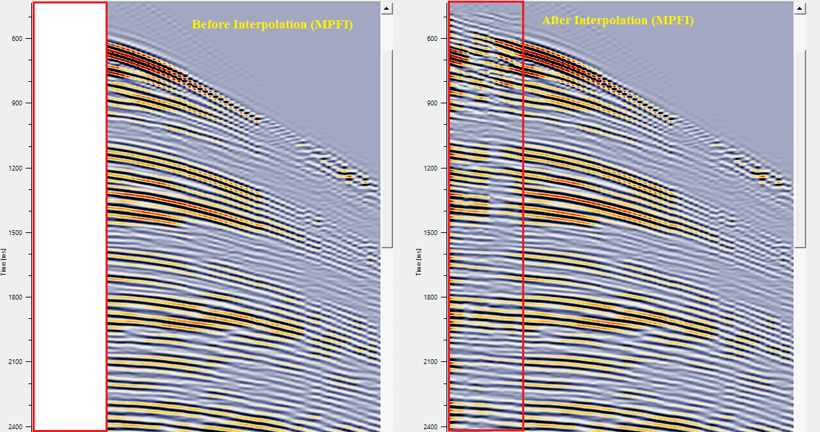
enables trace extrapolation to generate near-offset traces that are missing or sparsely sampled, improving offset coverage and gather regularity.
Extrapolated offsets step
defines the offset increment used when generating extrapolated traces. Smaller steps increase offset density but increase computation. By default, 25 m.
Extrapolated offsets aperture
specifies the maximum offset range over which extrapolation is performed. Limits how far extrapolated traces extend from existing data. By default, 200 m.
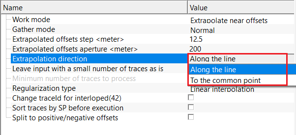
Extrapolation direction { Along the line, To the common point }
controls the spatial direction used for extrapolation. Along the line follows acquisition geometry, while To the common point extrapolates toward a reference location. By default, Along the line.
Work mode - Multiply traces
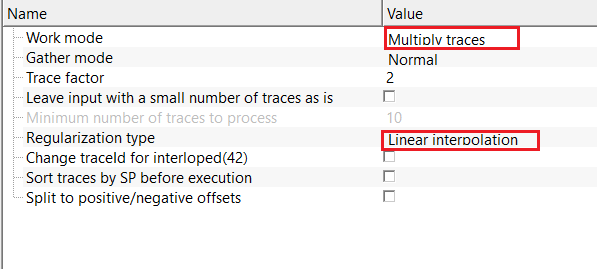
multiplies input traces by a constant factor. Useful for duplicating receivers/traces during multiple prediction model testing.
Trace factor
multiplier applied to each trace. By default, 2.
Work mode - Divide traces
used for dividing the previously multiplied traces or to reduce total number of traces by a specified factor.
Trace factor
divisor applied to trace. By default, 2.
Max aperture for divide
maximum number of neighboring traces used during division. Larger apertures improve stability but may reduce locality. By default, Zero(0).
Apply antialiasing
applies anti-aliasing filters during division and scaling operations. Recommended when strong amplitude variations or high frequencies are present. By default, FALSE(Unchecked).
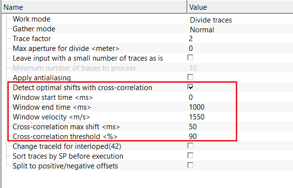
Detect optimal shifts with cross-correlation
enables automatic detection of relative trace shifts using cross-correlation prior to division. Improves alignment and stability. By default, FALSE(Unchecked).
Detect optimal shifts with cross-correlation - true
if it is TRUE(Checked), activates cross-correlation-based shift detection. Recommended when traces are misaligned in time.
Window start time
start time of the analysis window used for cross-correlation. Should include strong, coherent signal. By default, 0 ms.
Window end time
end time of the analysis window used for cross-correlation. The window length directly affects shift stability. By default, 1000 ms.
Window velocity
reference velocity used to flatten events within the correlation window. Improves shift estimation for dipping events. By default, 1550 m/sec
Cross-correlation max shift
maximum allowable time shift during cross-correlation. Prevents unrealistic or unstable alignment corrections. By default, 50 ms.
Cross-correlation threshold
minimum correlation coefficient required to accept a detected shift. Lower values allow more shifts; higher values enforce stricter quality control. By default, 90%.
Gather mode { Normal, CIG, OVT }
choose the input gather type from the drop down menu. By default, Normal.
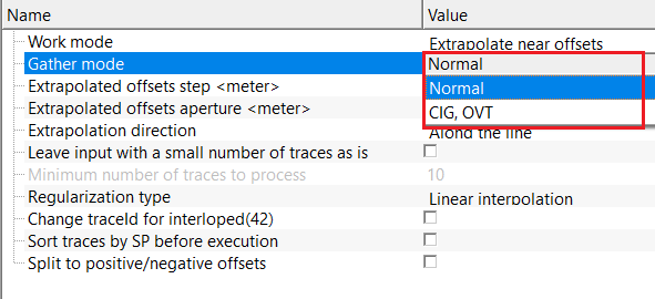
CIG - Common Image Gather
OVT - Offset Vector Tiles
Leave input with a small number of traces as is
by default, FALSE (unchecked). This option allows the user to keep the original input gather with lesser number of traces (as defined by user) as it is.
Leave input with a small number of traces as is - true
if it is TRUE (Checked), it will allow the user to specify the minimum number of traces to consider for interpolation in case the input gather is having less number of traces.
Minimum number of traces to process
provide the minimum number of traces should contain in the input gather to process the interpolation. Anything below this value, it will keep the original input gather as it is. By default, 10.
Settings
Auto-connection
By default, TRUE(Checked).It will automatically connects to the next module. To avoid auto-connect, the user should uncheck this option.
Bad data values option { Fix, Notify, Continue }
This is applicable whenever there is a bad value or NaN (Not a Number) in the data. By default, Notify. While testing, it is good to opt as Notify option. Once we understand the root cause of it, the user can either choose the option Fix or Continue. In this way, the job won't stop/fail during the production.
Notify
It will notify the issue if there are any bad values or NaN. This will halt the workflow execution.
Fix
It will fix the bad values and continue executing the workflow.
Continue
This option will continue the execution of the workflow however if there are any bad values or NaN, it won't fix it.
Number of threads
One less than total no of nodes/threads to execute a job in multi-thread mode. Limit number of threads on main machine.
Skip
By default, FALSE(Unchecked). This option helps to bypass the module from the workflow.
Output data
Output DataItem
Output gather
outputs interpolated gather as an output gather.
Information
There is no information available to this module so the user can ignore it.
Examples
In this example workflow, we are using MPFI interpolation method to extrapolate near offset(s) information. The input gather is a common shot gather.
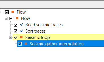
For this exercise, we are performing a near trace extrapolation by using MPFI regularization method. In the below image, we've set up the MPFI parameters as per the input data requirements. This exercise is very useful when the user wants to create a very good multiple prediction model. In general, the near offset information and is usually ranging from 100 - 150 meters. To extrapolate to zero offset, this option is very useful.
Similarly, the user can test different regularization schemes for different kinds of work modes i.e., multiplication of traces, division of traces, restoring missing traces by filling up the small to moderate data gaps.
Actions
There are no action items available of this module.
Video lesson
YouTube video lesson, click here to open [VIDEO IN PROCESS...]
Related articles
Yilmaz. O., 1987, Seismic data processing: Society of Exploration Geophysicist
 * * * If you have any questions, please send an e-mail to: support@geomage.com * * *
