![]()
![]()
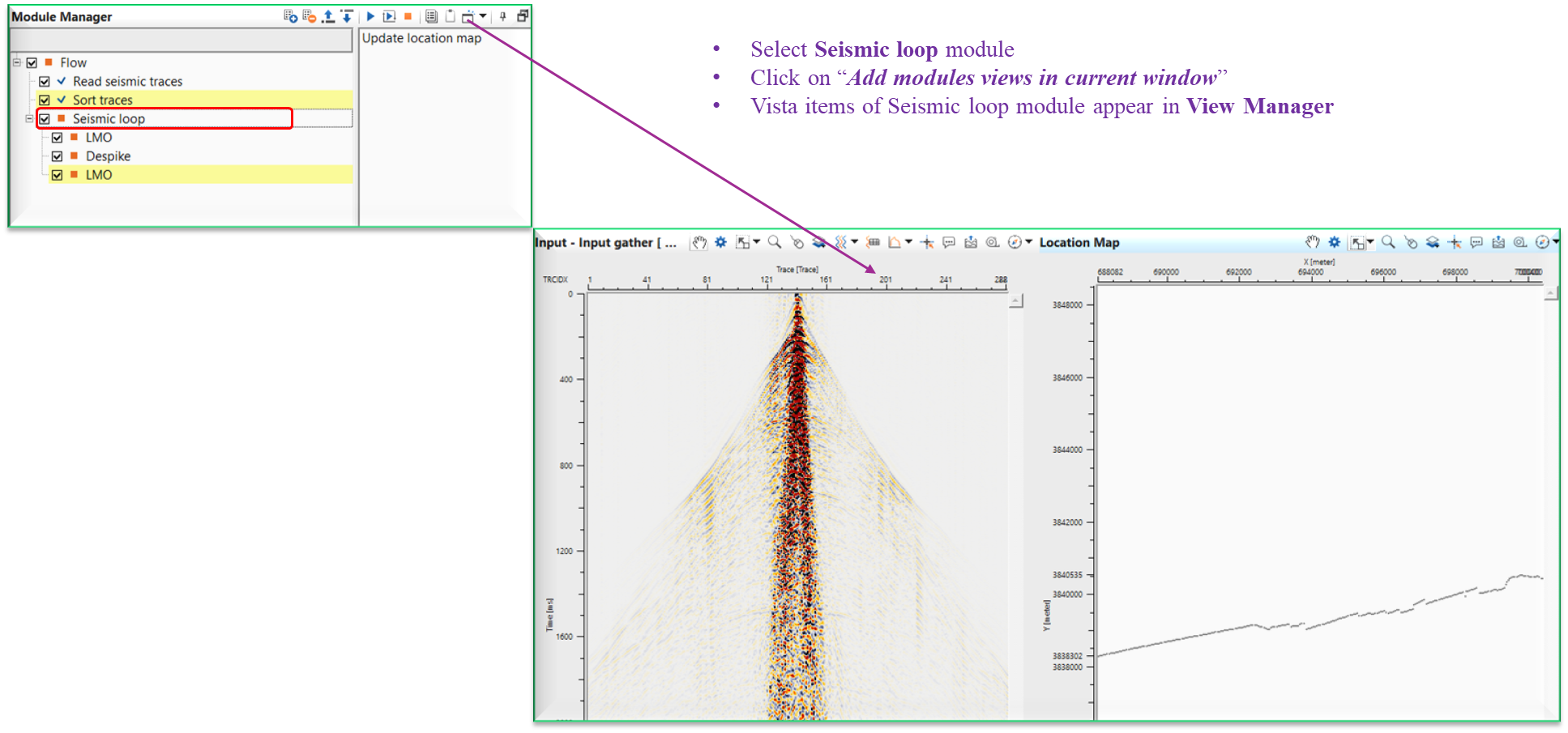
Seismic loop is an interactive procedure designed for processing prestack data in a gather by gather mode. Using this procedure, the user can create a sequence of specific processing modules that will be contained in the Seismic loop. Processing is performed on the seismic data based on the user specified sort order output from the Sort Traces module which must precede Seismic loop module in the workflow, and must provide the sorted input trace headers.
This module can also be used for quality control of input seismic data. Traces are displayed in accordance with the input sorting. Vistas that are interactively connected allow the user to step through a data volume, reviewing the results of the processing modules included in the Seismic loop processing sequence. Interactivity between the Location Map Vista and the Seismic display Vistas allow for random access to all gathers in the input seismic data.
There are multiple ways to display the Vista items (location map, input gather etc.) of Seismic Loop.
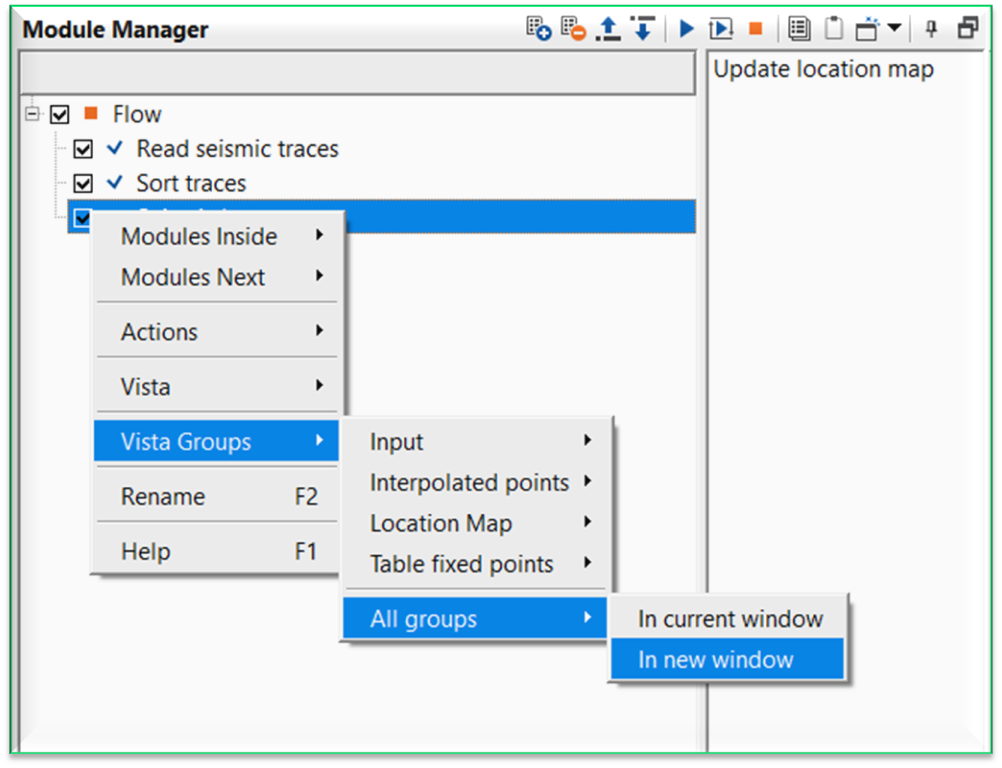
To display the Vista items of any module user should use MB3 (right mouse button) and select Vista Groups followed by All Groups. Now we have two options to choose.
In current window – Vista items will be added to the View Manager, however, if there are any existing vista items are there then the new vista items will be added to the existing one and it is often times confusing. To avoid this user should select “In new window” unless there are no existing Vista items
In new Window – Vista items will be added in a separate window in View Manager with the module name as the title to identify the module and it’s vista items.
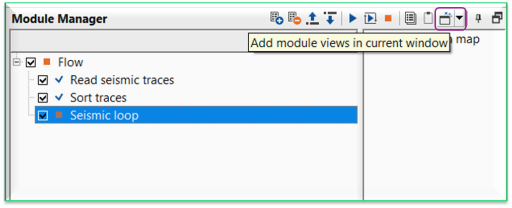
The second method is click on the icon  “Add module views in current window” on the top right corner of the Module Manager window as shown below.
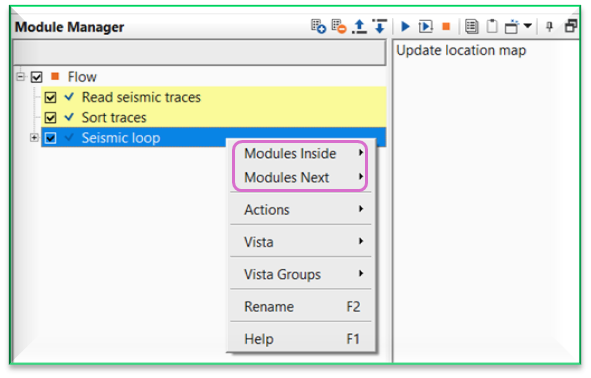
It is worth to mention that whenever the user wants to add a new module after Seismic loop, select Seismic loop module first and perform right mouse click on Seismic loop. It will give an option of Modules Inside, Modules Next besides the regular vista items etc.
![]() Modules inside option inserts the module within Seismic loop where as Modules Next option inserts the module outside the Seismic loop module.
Modules inside option inserts the module within Seismic loop where as Modules Next option inserts the module outside the Seismic loop module.
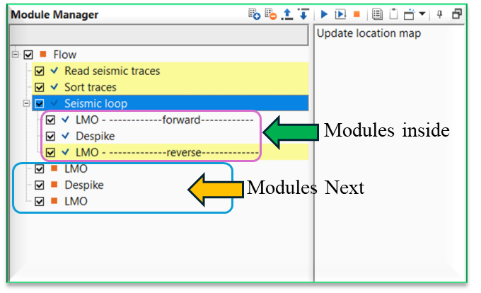
When user add the Vista items using this method, it is very useful in Seismic Loop. Click/select Seismic loop module and click Add module views icon. It will display the vista items as shown below.
When there are multiple modules existing inside the Seismic loop module, user can interactively see the results of the individual modules by simply selecting the module and go back and forth to see the resulting output of that particular module. To replicate this user, should do the following procedure.
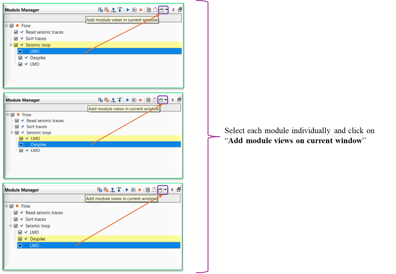
In the above image, the user added a new module LMO by using Modules inside option and it will be added under Seismic loop module. To display the vista items, we should click the icon “Add module views in current window” instead of MB3 or right mouse button click to see the interactivity of the tool.
Similarly, let’s add another module, Despike and follow the same procedure to add the vista items as we did earlier. Continue the same procedure for LMO (Reverse) to add the vista items in the current window by clicking on the Add module views in current window icon.
To see the animation of LMO and Despike outputs, we should select the individual modules and see the changes on the shot gathers.
Each modules vista items are stacked up on each other. This can be checked by clicking View Properties of any one of the Vista items windows i.e Input Gather or Output Gather or Difference gather (in case exists)
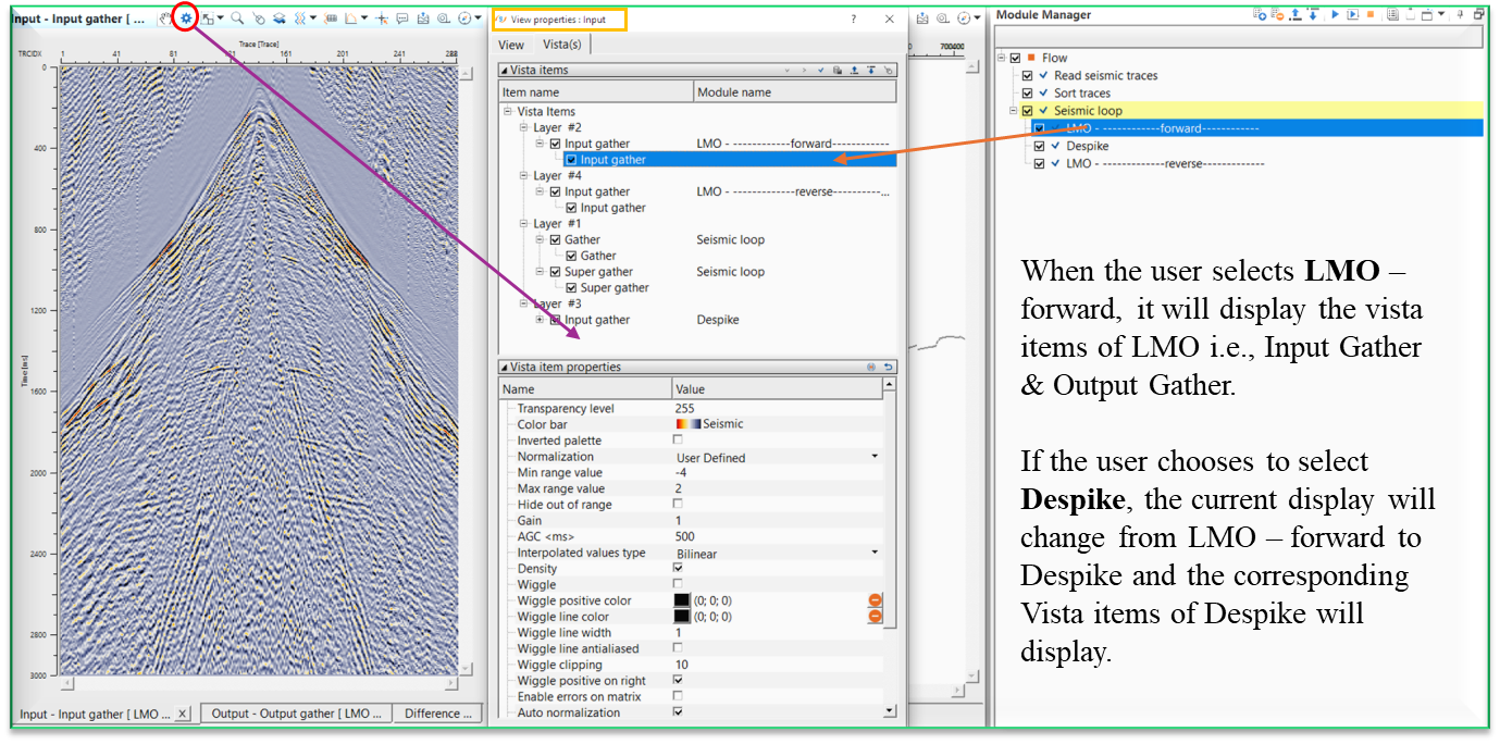
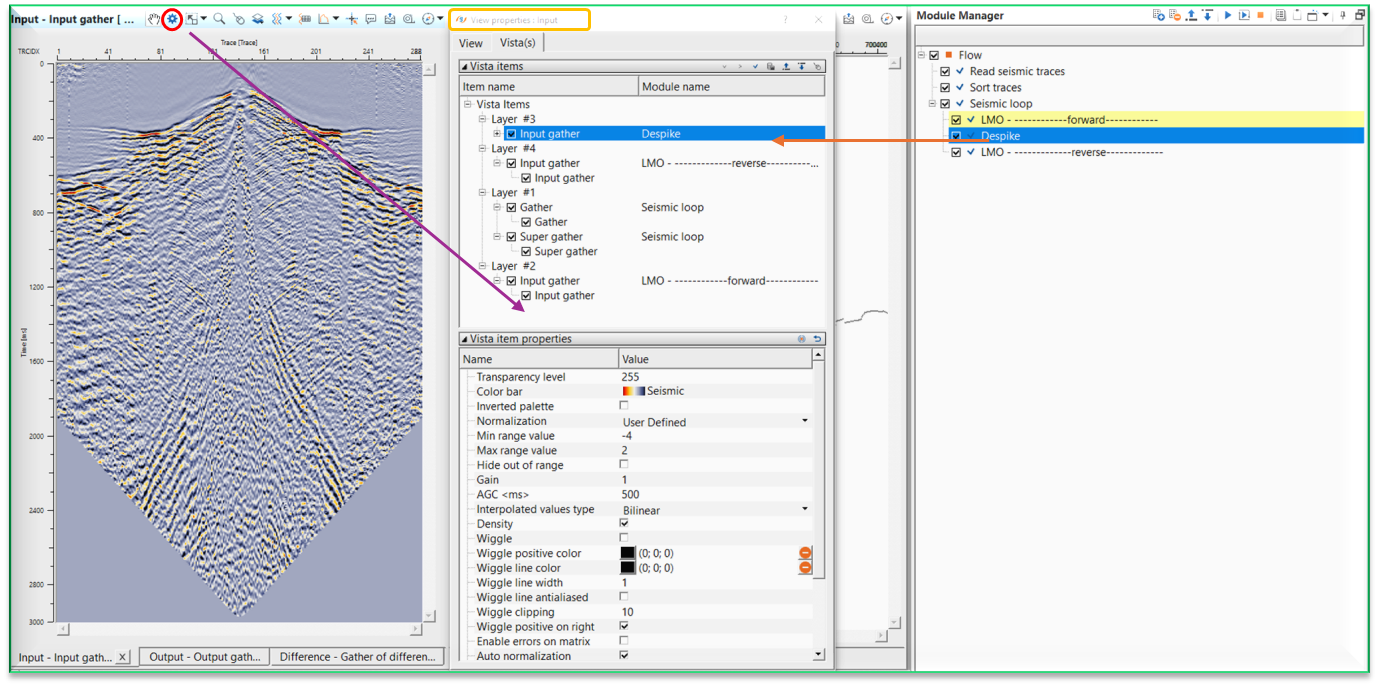
In the above image, we selected LMO and it’s vista items were added using the icon like wise we selected Despike module and added the vista items (below image) the same way. When we select LMO and Depsike modules, we can see the animation of the individual modules output results.
![]() There are couple of other important features within the Seismic loop module. If the user adds any modules within/inside the seismic loop, they need not to make the references since the reference/connections are automatic process. As you see on the Settings tab, Auto-connection option is checked. In the above example, Input to the seismic loop is from the Read seismic traces module, this will act as an input to the LMO module. After the LMO operation, output gather of LMO will act as an Input to the Despike module. Likewise output of Depsike will be Input to the next module LMO.
There are couple of other important features within the Seismic loop module. If the user adds any modules within/inside the seismic loop, they need not to make the references since the reference/connections are automatic process. As you see on the Settings tab, Auto-connection option is checked. In the above example, Input to the seismic loop is from the Read seismic traces module, this will act as an input to the LMO module. After the LMO operation, output gather of LMO will act as an Input to the Despike module. Likewise output of Depsike will be Input to the next module LMO.
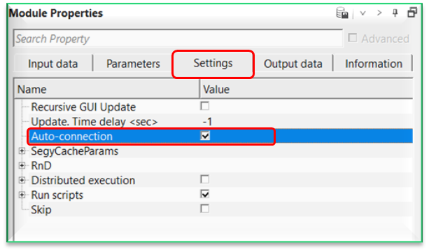
With Auto-connection turned ON, connections/references are automatically made. Within the seismic loop, it will be very useful. When any module is added inside the seismic loop, the Output gather of the current/previous module will be input gather for the next module. So it avoids the user to manually make the connections/references.
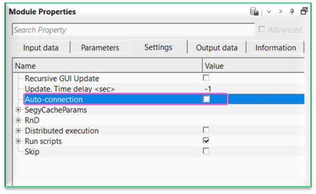
In case the user wants to override this auto-connection option, simply uncheck this option to make the necessary connections/references as per the user requirements.
What happens if the job stopped due to some reason? Do we need to rerun the entire line?
You don’t have to. In the Seismic loop Parameters tab, we can see the First seq. gather and Last seq. gather. If you know the last seq. gather number at the time of job stopped, then we can replace the First seq. gather with that number (at which seq number the job stopped) and keeping the Last seq. gather unchanged. Now the most important task is NOT to overwrite the existing output file name. This can be done at the Write output file where we should select the option “append” and uncheck the Rewrite if output exists option. So the process will continue from the new seq range and append to the existing gather of output file name. Also,
when the user submits the job with seismic loop in the workflow, the output from the seismic loop will have three outputs.
file.gsd.
file.gsd.sgy
file.tmp
file.tmp file is helpful in case the job is stopped for some reason. By going through this file, whenever the user resubmits the job it will automatically gets the information and restarts from the last seq gather.
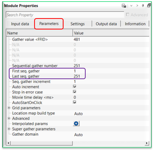
To explain in simple way, in the current dataset we have sequences from 1 to 251 and we submitted the job. Due to some reason our job didn’t finish. In the seismic loop parameters tab, we can see the Sequential gather number of the last sequence where the job failed. In this case we have 117. Now we replace the First seq. gather with 118 and keep the Last seq. gather 251 as it is.
![]()
![]()
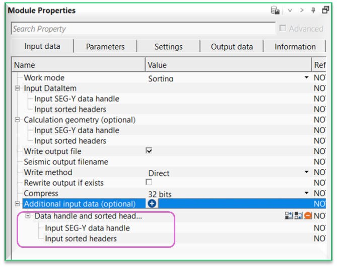
Work mode { Sorting, Free sorting } - this section deals with working mode of the input data. By default, Sorting which means the input data should be sorted already.
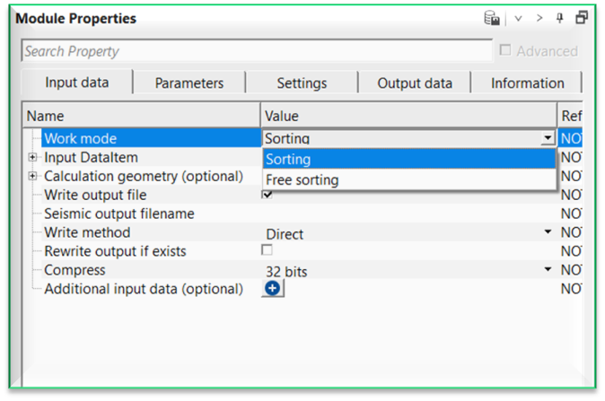
Work mode - Sorting
Input sorted headers - connect/reference to Output sorted headers.
Work mode - Free sorting
Input trace headers - connect/reference to Output trace headers.
Number of read traces - specifies the number of traces to read at a time.
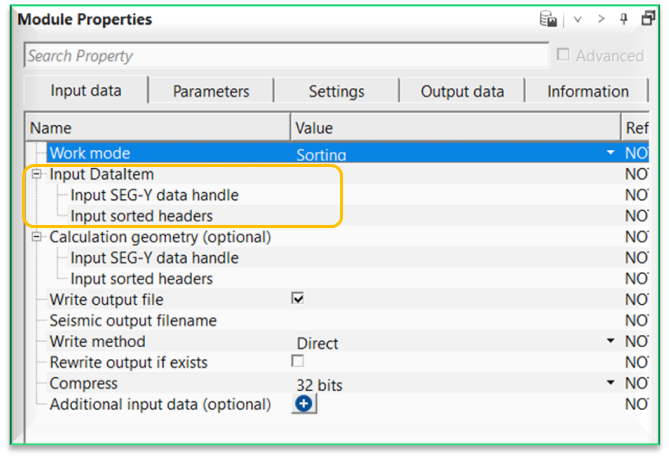
Input DataItem
Input SEG-Y data handle - connect/reference to Output SEG-Y data handle. The input data should be pre-stack data.
Calculation geometry (optional) - this section deals with additional input data that is used as a reference geometry. This is useful option whenever there are two different input gathers and the user wants to use this input gather geometry as a reference.
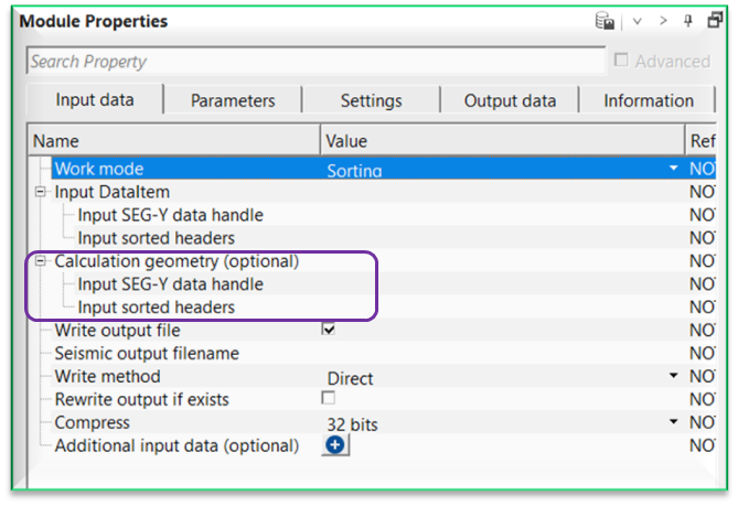
Input SEG-Y data handle - connect/reference to the Output SEG-Y data handle.
Input sorted headers - connect/reference to the Output sorted headers.
Write output file - this section deals with output gather. By default, TRUE(Checked).
Write output file - true
Seismic output filename - specify the file name and path of the output gather.
Write method { Direct, Direct - By sorting, Append } - specify what method is used for writing the output gather. By default, Direct.
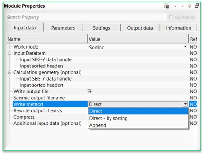
Direct - writes data directly to the output file in the order they are processed.
Direct - By sorting - sorts data internally based on required headers or indices before writing them directly to the output file.
Append - adds data to the end of an existing output file without overwriting previously written content.
Rewrite output if exists - this option will overwrite the output file if it is already exists in the database. By default, FALSE(UnChecked).
Rewrite output if exists - true - this will overwrite the existing output file.
Force rewrite output - it will rewrite the output file.
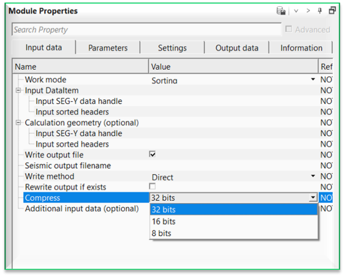
Compress { 32 bits, 16 bits, 8 bits } - this option allows the user to compress the output gather data size. By default, 32 bits.
Additional input data (optional) - this section deals with additional input data requirements. In case there are multiple input data sets are needed then the user can use this option to add additional input data. To add additional input data, click on  icon.
icon.
For example, when we've SRME input data & SRME model data as two input gathers then we use one as regular input gather and the second one as an additional input gather. At the time of Adaptive subtraction, we require two input gathers i.e., input and model. We connect/reference these input and additional input gathers to Adaptive subtraction and perform the adaptive subtraction.
![]()
![]()
First - Indicate on primary sorting of input data (from “Sort traces” module). This parameter is filled automatically with sorting header attribute
Second - Indicate on secondary sorting of input data (from “Sort traces” module). This parameter is filled automatically with sorting header attribute.
Sequential gather number - Number of current iteration. Can also be used for selection of gather in accordance with data sorting
First seq. gather - number of first iteration or the first sequence gather
Last seq. gather - number of last iteration or the last sequence gather
Seq. gather increment - sequence gather increment step. By default, 1.
Auto increment - if unchecked, the gather of the current iteration will not change.
Stop in error case - if checked, execution of the Seismic loop will stop if an error occurs.
Movie time delay - time delay between the iterations. It is used for automatic review of seismograms in movie mode
AutoStartOnClick - if checked, clicking on a gather location on the location map will run all of the procedures in the loop for the selected point.
Grid parameters - this section deals with how the input data is sorted and their corresponding headers will be processed. For example, if the input data is sorted as Inline, crossline then the iteration first step displays the inline step and iteration step second displays the cross line step. If the user wants to display every 10th inline and every crossline (step size of 1) then the user should mention it as 10 and 1. In case there are multiple sorted headers like source line, source sp, receiver line, receiver sp then the user should provide each headers step size. DO NOT confuse this with BIN Grid parameters.
Iteration step first - number of first iteration.
Iteration step second - number of second iteration
Iteration step third - number of third iteration
Iteration step fourth - number of fourth iteration
Iteration step firth - number of fifth iteration
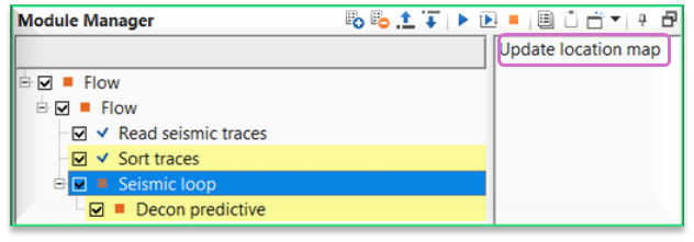
Location map build type { Off, Auto, By sources, By receivers, By bins } - it will automatically builds the location map. By default, Auto.
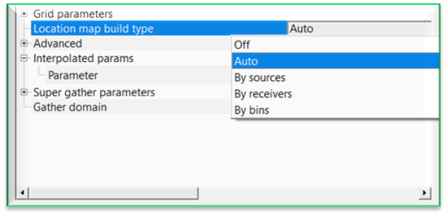
In case the user wants to build the location map based any one of the options available, select the corresponding item from the drop down menu and click "Update location map" action item. It will update the location map accordingly.
Advanced - this section deals with reading the input data while creating the location map etc.
Max bulks limit - it limits the maximum traces to read at a time as a bulk. By default, 1000
Buffer read size (standalone mode) - specifies the reading of the gathers in standalone mode. By default, 100
Use calculated state file - by default, TRUE(Checked).
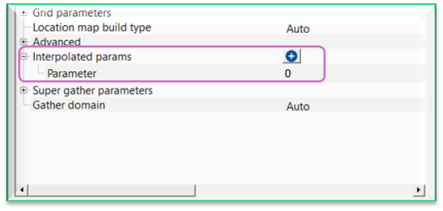
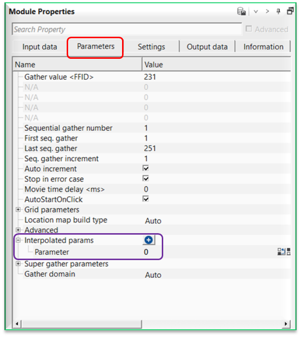
Interpolated params - this section deals with interpolation of parameters as per the user defined locations/points. This is useful whenever the user wants to use different parameters within the same seismic line but at different parts of the seismic line then it is very useful. Detailed explanation is available in Example section.
To add a parameter, click on  icon. It will add a new row with a text titled "Parameter" with a default value of 0.
Super gather parameters - this section deals with super gather parameters.
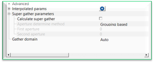
Calculate super gather - by default, FALSE(Unchecked). This option enables to calculate the super gather.
Calculate super gather - true - if TRUE(Checked), it allows the user to create super gather.
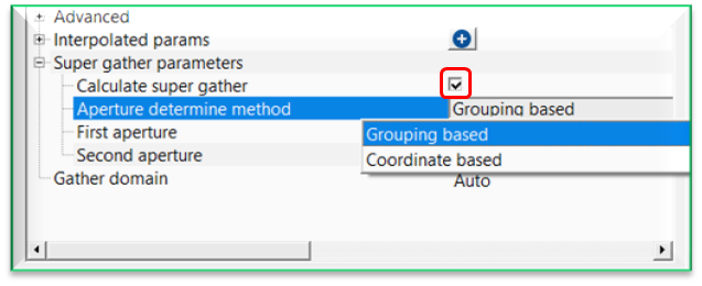
Aperture determine method { Grouping based, Coordinate based } - select the super gather aperture method from the drop down menu. Selects how neighboring traces are chosen to build the super gather.
Aperture determine method - Grouping based - determines the aperture using adjacent gather indices rather than physical distance.
First aperture - number of gathers included before the reference gather.
Second aperture - number of gathers included after the reference gather.
Aperture determine method - Coordinate based - determines the aperture using spatial coordinates of sources, receivers, or bins.
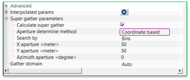
Search by { Sources, Receivers, Bins } - determines the aperture by searching the source/receiver/bin coordinates. By default, Bins.
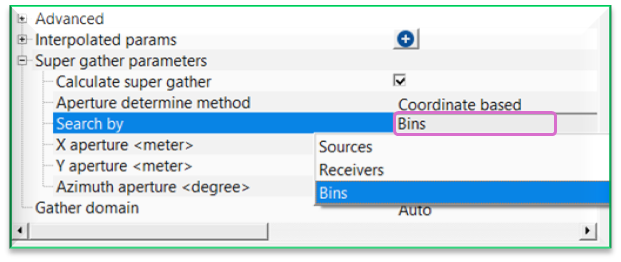
Sources - selects traces whose source coordinates fall within the defined aperture.
Receivers - selects traces whose receiver coordinates fall within the defined aperture.
Bin - selects traces whose bin/CMP coordinates fall within the defined aperture.
X aperture - maximum search distance in the X (inline/easting) direction.
Y aperture - maximum search distance in the Y (crossline/northing) direction.
Azimuth aperture - limits trace selection to a specified azimuth range.
Gather domain { Auto, TIME, DEPTH, FREQUENCY } - by default, AUTO, It will automatically detects the input gather and displays the input gather domain.
![]()
![]()
Recursive GUI Update - if TRUE (Checked), Seismic loop will automatically update the Vistas after each gather iteration
Update. Time delay - time delay between recursive Vista updates
Auto-connection - By default, TRUE(Checked).It will automatically connects to the next module. To avoid auto-connect, the user should uncheck this option. Within the seismic loop, it will be very useful. When any module is added inside the seismic loop, the Output gather of the current/previous module will be input gather for the next module. So it avoids the user to manually make the connections/references.
In case the user wants to override this auto-connection option, simply uncheck this option to make the necessary connections/references as per the user requirements.
SegyCacheParams
SegyReadParams - parameters for setting advanced parameters of reading seismic traces from disk.
Thread count (for SSD) - amount of treads for reading seismic traces from disk.
Bulk size (traces) - size of a chunk (data portion) for reading seismic traces from disk.
RnD - this section deals with R&D testing and it is not necessary for the regular user to pay attention to this.
Clear file name - clears the file name.
Distributed execution
Bulk size - chunk size is RAM in megabytes that is required for each machine on the server (find this information in the Information, also need to click on action menu button for getting this statistics):
Limit number of threads on nodes - limit numbers of of threads on nodes for performing calculations.
Job suffix - add a job suffix.
Set custom affinity - an axillary option to set user defined affinity if necessary.
Set custom affinity - true -
Affinity - add your affinity to recognize you workflow in the server QC interface.
Run scripts - it is possible to use user's scripts for execution any additional commands before and after workflow execution:
Script before run - path to ssh file and its name that will be executed before workflow calculation. For example, it can be a script that switch on and switch off remote server nodes (on Cloud).
Script after run - path to ssh file and its name that will be executed before workflow calculation.
Skip - By default, FALSE(Unchecked). This option helps to bypass the module from the workflow.
![]()
![]()
Output DataItem - this generates Output DataItem as a vista item. This can be used for connection/references for any module which requires Input DataItem.
Super gather - generates super gather as a vista item.
Gather - outputs the gather that can be used as an input gather for sub-sequent processing procedures.
Fixed points table - displays the parameter fixed points whenever the user uses the interpolation option.
Additional output gathers - this option will outputs additional output gathers (if at all the user provided additional input gathers at the beginning).
Number of traces written - displays the total number of traces written into the gather.
![]()
![]()
In this example workflow, we are explaining how to interpolated parameters within in Seismic loop. We consider Decon predictive module to apply deconvolution at different places and interpolate the values in between the sequences.
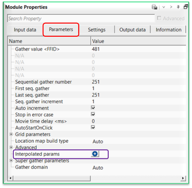
As shown in the image, we can see the Interpolated params at the bottom of the Parameters tab. Whenever user wants to apply specific process like band pass filter/deconvolution etc to a particular FFID/Shot/CMP range then they can use this option to interpolate the respective parameters.
Let us explain how it works. Within the seismic loop, let’s say user wants to apply deconvolution (Decon predictive) only to certain part of the line. In this case, they have to select the starting and ending points of the line and accordingly provide the parameters as shown below.
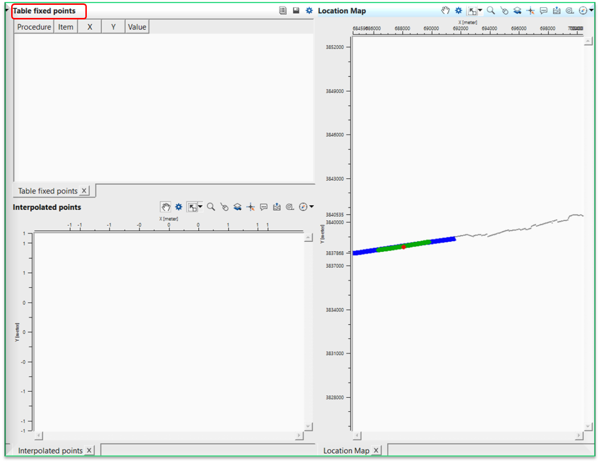
To select these points, user should add vista items of the Seismic loop. Initially Table Fixed points will be blank and nothing visible.
As the user added the Decon predictive module inside the seismic loop, go to Seismic loop parameters tab and click on the button. It will add a row named “Parameter”.
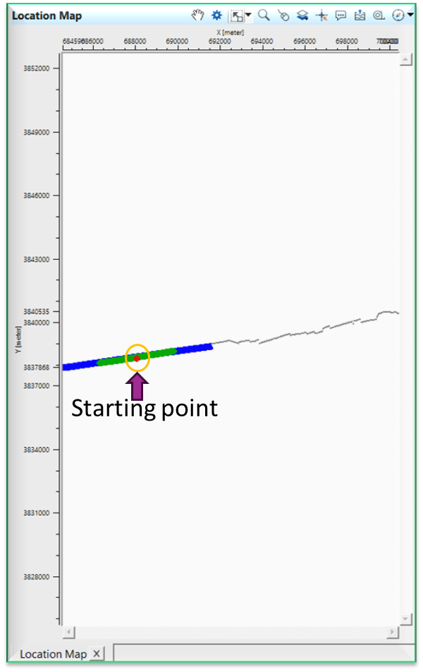
Here the user has to select the first location on the location map.
Now double click on Parameter of Interpolated params and it will open the reference window and assign the appropriate item. In this case, we select Predictive interval as the parameter.
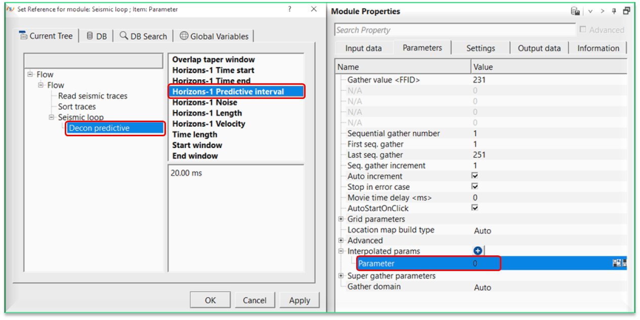
Once we click OK, then it will make the reference connection and display the first interpolation point on the Fixed points table as shown below.
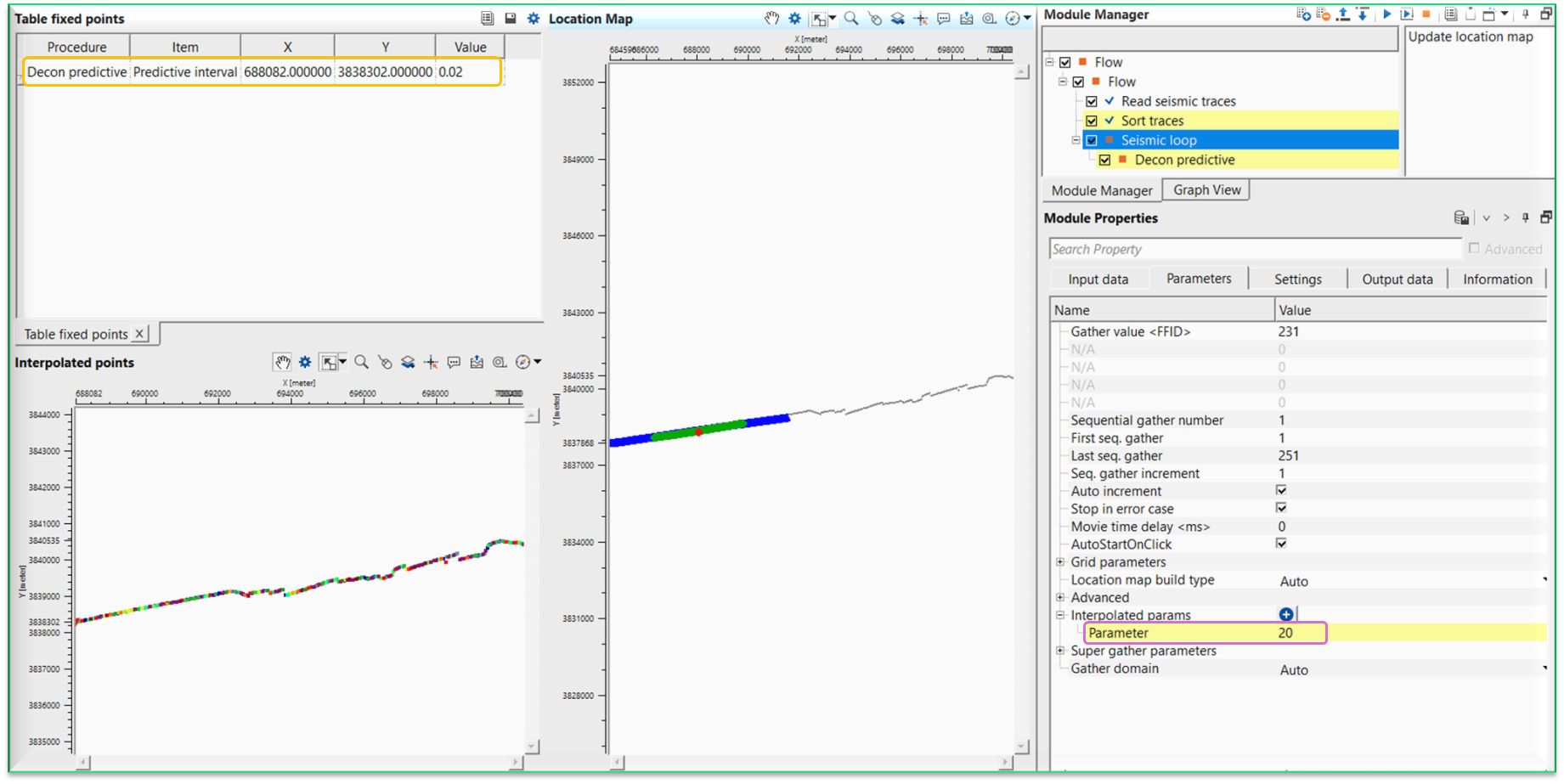
Now we can see that the Table fixed points where it added the information like procedure, item (predictive interval), x, y and value fields.Just below, we've Interpolated points map is displaying the interpolation points. Next, we've Location map where we select a point (red dot).
Likewise, we have to add predictive length also. For that, we have to click the button again on the Interpolated params and add another Parameter row to the existing one.
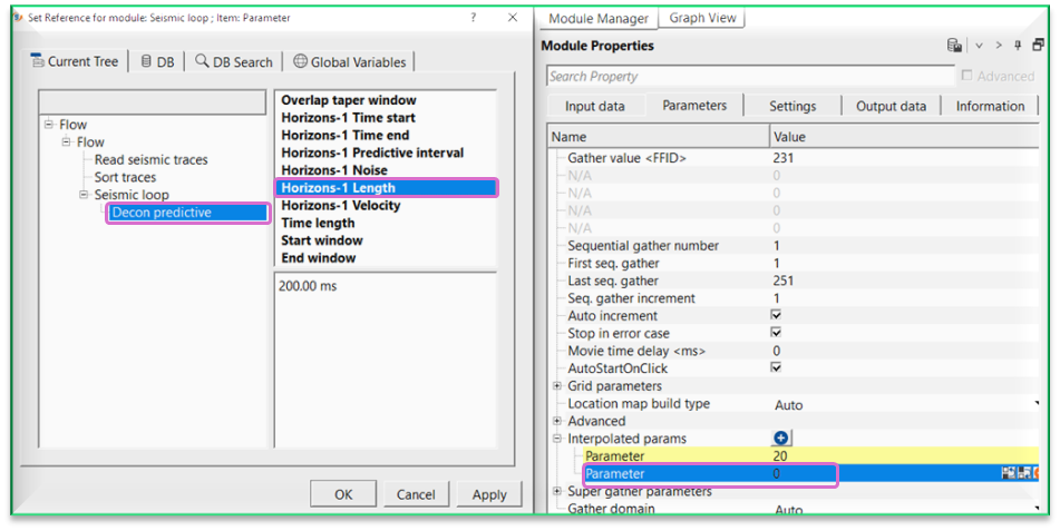
After this, we have to choose the other location point to do the interpolation between these two selected points as shown below.
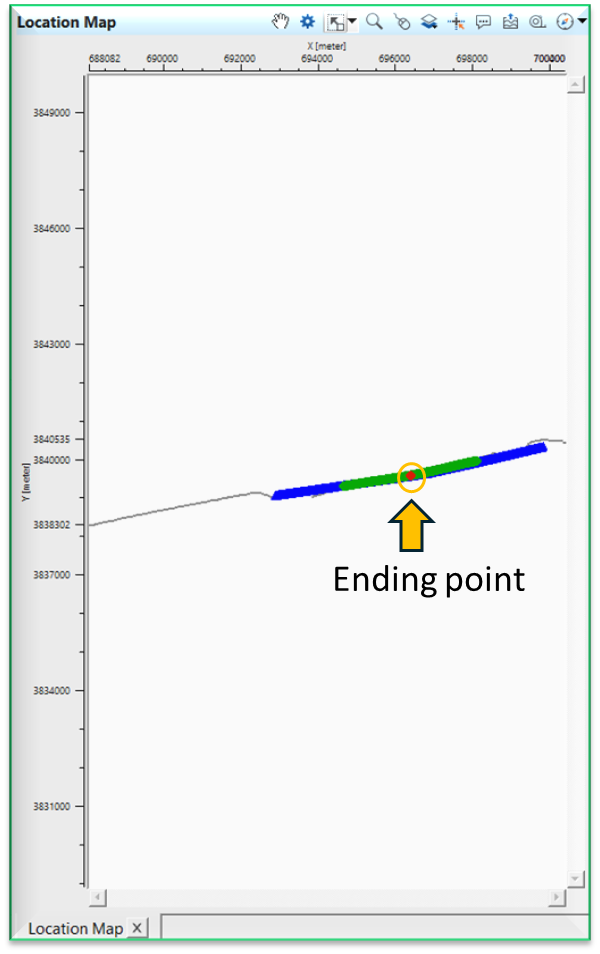
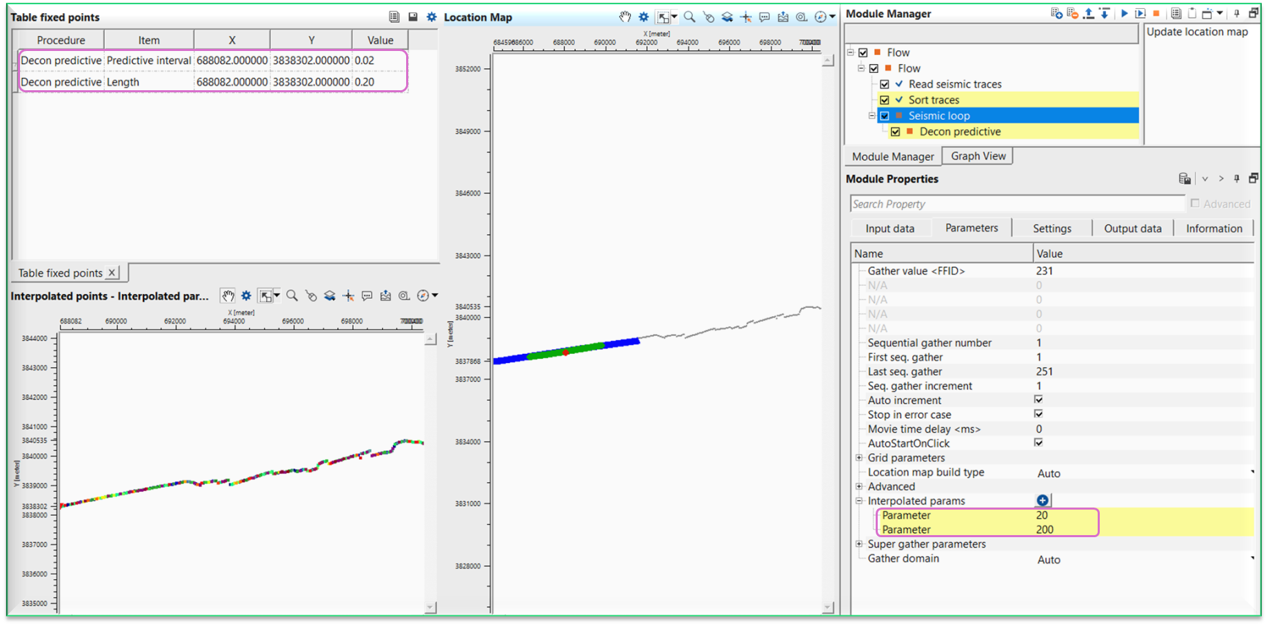
To do the interpolation, we need to change the Decon predictive parameters to new values at this new location. As soon as, we change the parameters, it will update the Table fixed points with new values and the Interpolated points map with starting and ending points with interpolated map. Beyond these points, it will use the actual values i.e. for starting point it will use it's values and for ending point it will use it's values.
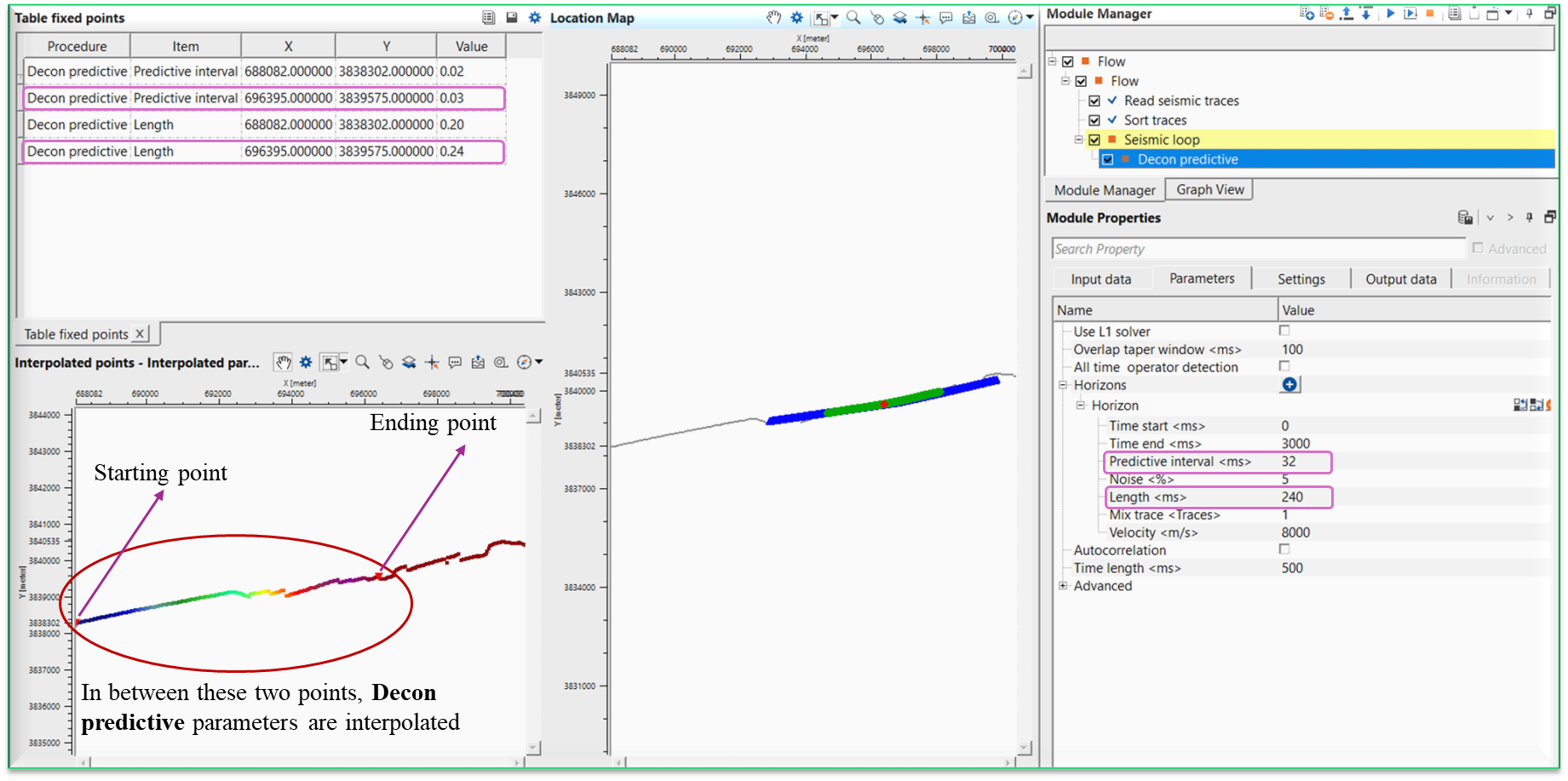
If we observe the above interpolated points map, it will interpolate the values between those two triangle only. This way we can able to interpolate parameters using seismic loop.
![]()
![]()
Update location map - this allows the user to update the location map upon launching the vista items.
![]()
![]()
YouTube video lesson, click here to open [VIDEO IN PROCESS...]
![]()
![]()
Yilmaz. O., 1987, Seismic data processing: Society of Exploration Geophysicist
 * * * If you have any questions, please send an e-mail to: support@geomage.com * * *