Description
Imaging - 3D ZO-MF is the final imaging step in the 3D Zero-Offset MultiFocusing (ZO-MF) workflow. It reads the results stored in the 3D MF search database, applies a velocity constrain corridor selected interactively by the user, and produces a zero-offset MultiFocusing stack along both inline and crossline directions. In addition to the stacked section, the module can generate a suite of MF attribute volumes such as semblance (correlation), emergence angle, wavefront curvature parameters (CRE, CEE), and velocity fields.
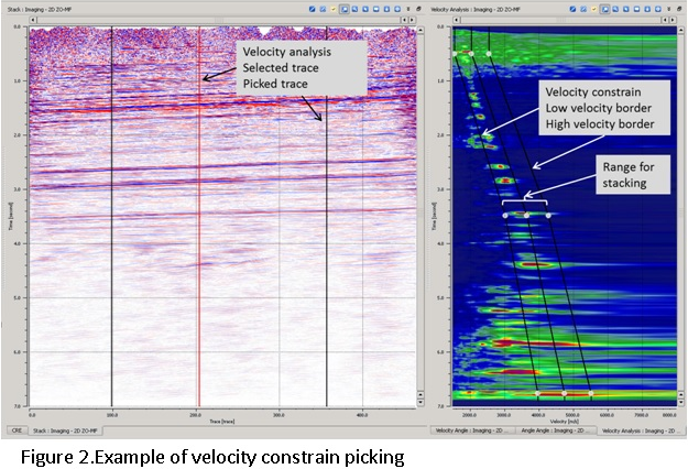
Unlike conventional CMP velocity analysis, MultiFocusing produces a multidimensional semblance cube that makes point-by-point velocity picking impractical. Instead, the user picks a velocity corridor (constraint) on the velocity semblance panel. The module then automatically selects the optimal MF parameters that fall inside that corridor at each time sample and uses them to form the stack. Corridor picking at a sparse set of bins is sufficient; values between picked locations are interpolated automatically, which reduces the risk of errors compared to dense velocity picking in CMP processing.
The interactive display provides a location map for bin navigation, inline and crossline stack sections with picking overlays, angle semblance and velocity semblance panels, and a velocity-angle slice panel. Picked velocity corridors from a linked procedure can be imported via the GMFPickingItem input to share constraints across modules.
Input data
Storage file 3D
Path to the 3D MF search database file (.kdb format) produced by the preceding Engine - 3D ZO-MF search step. This database contains all detected seismic events with their associated semblance values, two-way times, and MultiFocusing parameter indices for every bin in the 3D grid. The imaging module reads this database to reconstruct the optimal stack for each selected bin.
GMFPickingItem
Optional link to a velocity constrain picking item from another procedure. When provided, the velocity and angle corridor picks defined in the linked module are imported into this session, allowing the same velocity constraints to be shared and applied without re-picking. If no external picking is linked, corridors are picked interactively within this module.
Parameters
Image creation parameters
These parameters control how detected MF events are selected and combined to form the output stack. Each detected event stored in the MF database has a semblance value, a two-way time, and indices corresponding to its MF parameters (angle and velocity). During imaging, events are filtered by angle range, minimum separation criteria, and semblance threshold before being summed together. Only events whose MF parameters fall inside the user-picked velocity corridor contribute to the final stack.
Directions
Maximum number of events (dipping reflectors) to be stacked at each time sample. The MF search can detect multiple crossing events at a single time; this parameter limits how many of those events are included in the sum. Set to 1 for a standard single-event stack. Increase to 2 or more only when multiple simultaneous reflectors are expected and the semblance cube clearly shows distinct peaks. Default: 1. Valid range: 1 to the maximum number of directions preserved during the MF search.
•Semblance value
•Time
•And indexes corresponding to the MF parameter
During the stacking can be applied different criteria for selection: by angle range, by velocity range or by semblance distribution.
From angle
Lower bound of the emergence angle range used to filter events before stacking, in degrees. Events with an emergence angle smaller than this value are excluded. Use a value of -90 to include all negative-angle events (dips toward smaller trace numbers). Default: -90. Valid range: -90 to 0.
•Default: -90
•Range: -90 to 0
To angle
Upper bound of the emergence angle range, in degrees. Events with an angle exceeding this value are excluded from the stack. Use 90 to include all positive-angle events. Narrowing the range (for example, -30 to 30) suppresses steeply dipping noise while retaining near-horizontal reflections. Default: 90. Valid range: 0 to 90.
•Default: 90
•Range: 0 to 90
SN Enhance
When enabled, each trace contribution to the stack is weighted by its semblance value before summation. This signal-to-noise enhancement emphasizes high-coherence events and suppresses low-coherence (noisy) events, typically producing a cleaner stack at the cost of slightly reduced amplitude fidelity. Disable this option when true amplitude preservation is required. Default: off.
Correlation threshold
Minimum semblance value, expressed as a percentage of the local maximum semblance, that an event must reach in order to contribute to the stack. Events with semblance below this threshold are discarded. A value of 10% (default) passes most events while rejecting those with negligible coherence. Increase this value (for example to 30-50%) in noisy data to keep only highly coherent events. Default: 10. Valid range: 10 to 90.
•Default: 10
•Range: 10 to 90
Min angle distance selection
Minimum separation between selected events along the angle axis of the semblance grid, measured in grid cells. This prevents the algorithm from selecting two closely spaced events that correspond to essentially the same physical reflector. Increase this value when the angle semblance shows closely packed peaks that belong to a single reflector rather than two distinct ones. Default: 1. Valid range: 1 to 100.
•Default: 1
•Range: 1 to 100
Min radius distance selection
Minimum separation between selected events along the velocity (radius) axis of the semblance grid, measured in grid cells. This prevents double-counting events that lie very close together in velocity space. Use larger values when the velocity semblance shows smeared peaks to ensure that only one representative event per velocity cluster is selected. Default: 100. Valid range: 1 to 100.
Default: 100
Range: 1 - 100
Visualization
These settings control how the stacked sections and velocity semblance panels are displayed interactively. They affect only the on-screen visualization and do not change the data written to the output files.
Shift to datum
When enabled, the displayed inline and crossline stacked sections are shifted to a flat datum elevation for visual comparison. This is useful for surveys with significant surface topography: enabling this option removes the time distortion caused by elevation differences so that reflections appear at their true relative depths. The actual output data is not affected. Default: off.
Default: false
Datum
Elevation of the flat datum reference level used for visualization shifting, in meters. This value is only active when Shift to datum is enabled. Set it to the target datum elevation (for example, mean sea level or a project-specific reference plane). Default: 0 m.
Default: 0
VelocityAGC
Automatic Gain Control window length applied to the velocity semblance display panels, in seconds. A shorter window (for example, 0.2 s) increases the local contrast in the semblance display so that weak peaks become more visible. A longer window (for example, 1.0 s) provides a more uniform display suitable for comparing semblance amplitude across the time axis. This parameter affects the display only, not the imaging computation. Default: 0.6 s.
PickingOnly
When enabled, the module operates in picking-only mode: the interactive display shows velocity and angle semblance panels for corridor picking, but no stacked output sections are computed or displayed. Use this mode when you only need to define or refine the velocity corridor without waiting for the full stack to be generated. Default: off.
Map
Controls which bin is currently selected for display in the inline/crossline stack and semblance panels. Change the inline and crossline numbers here to navigate the 3D survey and inspect the MF imaging results at any bin location.
Option for magnet
Determines how a mouse click on the location map snaps to the nearest calculated bin. Cross (default) selects the nearest bin at the intersection of the calculated inline and crossline lines simultaneously, updating both the inline and crossline display sections. Single snaps only to the single nearest calculated bin regardless of which line it belongs to. No magnet disables automatic snapping.
•Cross - will select nearest bins located on intersection of calculated inlines and crosslines
•Single – will select nearest calculated bin
Default: cross
Inline
Inline number of the bin currently selected for display. Changing this value switches the inline stack section and all associated semblance panels to the specified inline. Default: 0 (first inline in the dataset).
Default:0
Value: inline range
Crossline
Crossline number of the bin currently selected for display. Changing this value switches the crossline stack section and semblance panels to the specified crossline. Default: 0 (first crossline in the dataset).
Default:0
Value: crossline range
Band-pass
Optional trapezoidal band-pass filter applied to the stacked sections and velocity semblance panels before display. The filter is defined by four corner frequencies that form a trapezoidal shape in the frequency domain. This is a visualization filter only and does not affect exported output. Enable it to suppress low-frequency noise or high-frequency aliasing artifacts when inspecting the stack interactively.
Apply Band-pass
Enables or disables the band-pass filter. When off, the sections are displayed without any frequency filtering. Default: off.
Default: false
Frequency 1
Low-cut start frequency of the trapezoidal band-pass filter, in Hz. Frequencies below this value are fully suppressed. Default: 1 Hz.
Default: 1
Frequency 2
Low-cut end frequency (low-pass ramp end) of the band-pass filter, in Hz. Frequencies above this value and below Frequency 3 pass without attenuation. Default: 5 Hz.
Default: 5
Frequency 3
High-cut start frequency (high-pass ramp start) of the band-pass filter, in Hz. Frequencies above this value begin to be attenuated. Default: 100 Hz.
Default: 100
Frequency 4
High-cut end frequency of the band-pass filter, in Hz. Frequencies above this value are fully suppressed. Default: 105 Hz.
Default: 105
Export Params
These parameters control the spatial range and format of MF attribute volumes written to output SEG-Y files when the Export params to sgy action is triggered. The inline/crossline range limits the export to a sub-volume of interest; setting all values to -1 exports the full 3D grid. Use the Write mode and data-handling options to control how the output files are organized.
3D From Inline
First inline number included in the export. Set to -1 to start from the beginning of the 3D grid. Default: -1.
Default:-1
Value: inline range
3D To Inline
Last inline number included in the export. Set to -1 to export through the last inline of the 3D grid. Default: -1.
Default:-1
Value: inline range
3D From Crossline
First crossline number included in the export. Set to -1 to start from the first crossline. Default: -1.
Default:-1
Value: crossline range
3D To Crossline
Last crossline number included in the export. Set to -1 to export through the last crossline. Default: -1.
Default:-1
Value: crossline range
Write mode
Controls how the output SEG-Y files are written when exporting MF parameters. Direct (default) overwrites any existing output file with a fresh export. Append adds the newly exported traces to the end of an existing output file, which is useful when exporting large surveys in multiple passes or when accumulating results from separate inline/crossline ranges into a single file.
Default: direct
Values: direct, append
Convert To Feet
When enabled, velocity values and distance measurements in the exported MF parameter files are converted from meters to feet. Enable this option when the project uses the imperial measurement system or when the output is intended for software that expects feet-based units. Default: off.
No Zero Values For Velocity
When enabled, any time samples in the velocity output that have a value of zero (meaning no valid MF solution was found) are replaced by the background velocity V0 (the near-surface reference velocity used during the MF search). This prevents downstream applications from misinterpreting zero as a valid velocity. Default: off.
Zero padded
When enabled, bins that were not computed during the MF search (zero fold) are included in the exported SEG-Y as traces filled with zeros. This preserves the complete 3D grid geometry in the output, which can be important for downstream cube-based interpretation workflows. When disabled, only bins that have valid MF results are written, and the output SEG-Y may have gaps in the bin grid. Default: off.
Shift to datum
When enabled, the exported MF attribute sections are shifted to the flat datum elevation defined by the Datum (export) parameter. This applies the same static correction to the exported data as the visualization shift, ensuring that the output SEG-Y traces are referenced to a flat datum rather than to the actual surface topography. Default: off.
Default: false
Datum
Elevation of the flat datum reference level for export, in meters. Active only when Shift to datum (export) is enabled. Set this to the same datum elevation used throughout the processing project. Default: 0 m.
Default: 0
Types
Selects which MF attribute sections to compute and make available as output. Each enabled type creates both an interactive visualization panel and a dedicated output gather that can be connected to a downstream export or display module. Only enable the attributes you need, because computing many attribute volumes simultaneously increases processing time. The Stack section is always enabled by default.
Stack
Produces the primary Zero-Offset MultiFocusing stacked section. Each sample is formed by summing time-corrected seismic events that satisfy the image creation criteria and fall within the picked velocity corridor. This is the main deliverable of the MF imaging workflow. Default: on.
Default:true
Correlation
Produces the MF semblance (coherence) section. Each sample contains the semblance value of the optimal event selected at that bin and time. High values indicate strongly coherent reflections; low values indicate noise or poorly focused events. Use this section as a confidence map for the stack and for picking quality control. Default: off.
Default: false
Angle
Produces the MF emergence angle section. Each sample contains the optimal emergence angle (in degrees) of the dominant reflector at that bin and time. This section can be used to estimate structural dip and to identify dipping events that may require special treatment in further processing. Default: off.
Default: false
Gamma
Produces the MF Gamma parameter section. Gamma is the ratio of the CRE and CEE wavefront curvatures (V_slow / V_fast) and describes the reflector curvature in the MF framework. It is useful for geomechanical and structural interpretation. Default: off.
CRE
Produces the Common Reflection Element (CRE) radius section. The CRE radius is the radius of curvature of the Common Reflection Surface (CRS) in the CRE direction, which corresponds to the in-dip direction. It characterizes the subsurface curvature of the reflector and can be used for geomorphological analysis. Default: off.
Default: false
CRE2
Produces the secondary CRE parameter section (squared or normalized variant of the CRE radius). This parameter is used internally in the 3D MF formulation and may be required for certain post-processing or attribute extraction workflows. Default: off.
CRE Azimuth
Produces a section showing the azimuth angle of the CRE wavefront curvature direction, in degrees. In 3D surveys this indicates the orientation (azimuth) of the principal curvature axis of the subsurface reflector, providing information about structural strike direction. Default: off.
CEE
Produces the Common Evolution Element (CEE) radius section. The CEE radius is the radius of curvature in the CEE direction (perpendicular to the CRE direction, corresponding to the along-strike direction). Together with the CRE radius, it fully describes the 3D reflector curvature. Default: off.
Default: false
CEE2
Produces the secondary CEE parameter section (squared or normalized variant of the CEE radius). Default: off.
CEE Azimuth
Produces a section showing the azimuth angle of the CEE wavefront curvature direction, in degrees. This parameter complements the CRE Azimuth and together they define the full 3D orientation of the reflector curvature ellipse. Default: off.
V Slow
Produces the VRMS-MF (slow velocity) section, in m/s. This is the RMS velocity in the direction of minimum velocity (along the CRE direction), derived from the optimal MF parameters. It can be used as input to interval velocity estimation and depth conversion. Default: off.
Default: false
V Fast
Produces the fast velocity section, in m/s. This is the RMS velocity in the perpendicular (CEE) direction. In isotropic media V Fast equals V Slow; differences between the two indicate azimuthal velocity anisotropy or dip effects. Default: off.
Dip
Produces the MF dip angle section, in degrees. This is the total apparent dip of the reflector derived from the optimal emergence angle, expressed as an angle from horizontal. Use this section for structural mapping and dip-steering applications. Default: off.
Azimuth Dip
Produces the azimuth of the dip direction section, in degrees. Combined with the Dip section, this fully describes the 3D dip vector of each reflector and can be used for automatic structural interpretation or dip-steering workflows. Default: off.
VSlow / cos(Dip)
Produces an approximation of the conventional CMP stacking velocity, computed as V Slow divided by the cosine of the reflector dip angle, in m/s. This attribute bridges the MF velocity model and the conventional NMO velocity, allowing direct comparison with CMP-derived velocity picks or use in standard NMO correction workflows. Default: off.
Default: false
VFast / cos(Dip)
Produces the fast-velocity equivalent of the CMP stacking velocity approximation (V Fast / cos(Dip)), in m/s. Useful for analyzing azimuthal velocity variation and for comparing the MF velocity field against conventional velocities in directions perpendicular to the dip. Default: off.
Fold
Produces the MF fold section. Each sample records the number of events that contributed to the stack at that bin and time. Low-fold areas may indicate poor illumination or gaps in the MF search coverage. Inspect the fold section when evaluating the reliability of the stack in specific regions. Default: off.
Default: false
Velocity Analysis– Unlike the CMP processing MF has multidimensional semblance cube that makes picking too complex. For this picking of velocity function in MF replaced by picking of velocity corridor (constrain), the optimal parameters of MF selected automatically. For stacking will be used only events located inside the velocity constrain. Between two locations the velocity constrain interpolated, interpolation of velocity corridor reduce possibility of error in contrast to velocity interpolation during CMP velocity analysis (Figure 2).