Description
Function for imaging of the results of 2D ZO-MF search for multi line projects.
This module produces a zero-offset (ZO) MultiFocusing (MF) stacked section from precomputed MF search databases for multi-line 2D projects. Each seismic line in the project has its own database of MF search results, and this module reads them all simultaneously. The user navigates between lines using the Location Map display and applies a velocity corridor (constraint) to guide the stacking. The optimal MF parameters within the corridor are selected automatically, and events outside the corridor are excluded from the stack. Between picked velocity corridor locations, the corridor is spatially interpolated across the line, reducing the risk of picking errors compared to conventional CMP velocity interpolation.
The module is interactive: the processor views semblance projections (angle and velocity axes), picks velocity and angle corridors at key locations, and then recreates the stack for review. When satisfied, the MF parameters and the stacked section are exported. Custom actions available in this module are: Clear all picking, Load picking, Save picking, Export params to sgy, and Recreate all stacks.
Output data – MF parameters;
Visual – Location map, Projections of the semblance cube, Output gathers.
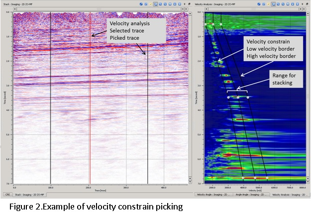
Velocity Analysis– Unlike the CMP processing MF has multidimensional semblance cube that makes picking too complex. For this picking of velocity function in MF replaced by picking of velocity corridor (constrain), the optimal parameters of MF selected automatically. For stacking will be used only events located inside the velocity constrain. Between two locations the velocity constrain interpolated, interpolation of velocity corridor reduce possibility of error in contrast to velocity interpolation during CMP velocity analysis (Figure 2).
Input data
MF Storage Driver Collection
Collection of databases with calculated MF parameters, single file for each line
Add one database file (.kdb) per 2D seismic line. Each file must contain the results of a previous MF Search (Engine - 2D ZO-MF) run for that line. The order in which files are added corresponds to the order of lines as they appear in the Location Map.
GMFPickingItem
Link to velocity constrain picking that can be taken from another procedure
Optional. When connected, pre-existing velocity corridor picks from another imaging session are imported and used as a starting point. This allows the user to reuse picking work across multiple runs without starting from scratch.
Output data
The module produces a set of output gathers, each corresponding to a selected output type (enabled in the Types parameter group). Only enabled types are computed and written to output. The following output data items are available:
Image Stack — The primary zero-offset MultiFocusing stacked section. This is the main deliverable of the imaging step.
Interpolated Stack — A version of the stack produced using spatially interpolated MF parameters between picked locations.
GatherCorrelation — Section of MF semblance (correlation) values. Higher values indicate stronger waveform coherence across offsets.
GatherAngle — Section of the MF emergence angle parameter. Represents the dip direction of the optimally stacked event at each time sample.
GatherGamma — Section of the MF gamma parameter, which describes the wavefront curvature asymmetry (related to reflector dip in the subsurface).
GatherCRE — Section of the Common Reflection Element (CRE) radius parameter. Used for kinematic wavefield attributes and subsequent depth conversion.
GatherCRE2 — Section of the squared CRE radius. An alternative form of the CRE attribute used in some inversion workflows.
GatherCREAzimuth — Section of the CRE azimuth parameter. Available for 3D-capable workflows; indicates the azimuthal direction of the CRE vector.
GatherCEE — Section of the Common Evolution Element (CEE) radius parameter, related to the near-surface wavefront curvature.
GatherCEE2 — Section of the squared CEE radius.
GatherCEEAzimuth — Section of the CEE azimuth parameter.
GatherVSlow — Section of the slow stacking velocity (NMO velocity in the inline direction for dipping reflectors).
GatherVFast — Section of the fast stacking velocity (the orthogonal velocity component to VSlow).
GatherDip — Section of the reflector dip angle derived from the optimal MF parameters.
GatherAzimuthDip — Section of the dip azimuth angle.
GatherVSlowCosDip — Section of VSlow divided by the cosine of the dip angle. This is the true vertical stacking velocity corrected for dip, useful in depth conversion.
GatherVFastCosDip — Section of VFast divided by the cosine of the dip angle.
GatherFold — Section showing the number of MF events summed at each sample location. Useful for quality control of coverage across the stack.
Parameters
Polygon picking params
Gives possibility to change creation parameters in some areas. Usually used on the late stages of processing/interpretation
This parameter group controls the velocity and angle constraints applied within a user-defined polygon area. By defining a polygon on the section, the user can override the global velocity corridor and angle range locally. This is particularly useful for handling areas with complex geology — for example, salt flanks, faults, or shallow anomalies — where a different stacking constraint is needed than for the rest of the line.
PolygonId
Polygon identification
Default:0;
Numeric identifier of the polygon whose parameters are currently displayed. When multiple polygons are defined, change this value to switch between them and inspect or modify each polygon's settings independently.
MinVelocity
Minimum stacking velocity for polygon area
Default: 0;
The lower bound of the velocity corridor within the selected polygon, in m/s. MF events with stacking velocities below this value are excluded from the stack within the polygon area. Set this together with Max Velocity to define a narrow velocity window targeting a specific geological interval.
MaxVelocity
Maximum stacking velocity for polygon area
Default: 0;
The upper bound of the velocity corridor within the selected polygon, in m/s. MF events with stacking velocities above this value are excluded. When both Min Velocity and Max Velocity are set to 0, no velocity filtering is applied within the polygon.
UseAngle
Use specified angle range
Default:false;
When enabled, only MF events whose emergence angle falls within the range defined by Min Angle and Max Angle are included in the stack for this polygon. Enable this option to suppress steeply dipping noise or to focus stacking on a specific dip range within a problem zone.
Clear Angle Inside Area
Do not take specified angle range during stacking
Default: false;
When enabled, the angle range defined by Min Angle / Max Angle is excluded from stacking (inverted selection). Use this option to mute a specific dip range within a polygon — for example, to suppress a coherent noise train arriving at a known angle.
MinAngle
Minimum angle for polygon area
Default: 0;
The lower bound of the emergence angle range within the polygon, in degrees. Active only when Use Angle is enabled. Valid range: -90 to 0 degrees.
MaxAngle
Maximum angle for polygon area
Default: 0;
The upper bound of the emergence angle range within the polygon, in degrees. Active only when Use Angle is enabled. Valid range: 0 to 90 degrees.
UseGamma
When enabled, only MF events whose gamma parameter falls within the range defined by Min Gamma and Max Gamma are included in the stack for this polygon. The gamma parameter describes wavefront curvature asymmetry and is related to subsurface reflector dip. Default: false.
MinGammae
The lower bound of the gamma range within the polygon, in degrees. Active only when Use Gamma is enabled. Valid range: -90 to 90 degrees. Default: 0.
MaxGamma
The upper bound of the gamma range within the polygon, in degrees. Active only when Use Gamma is enabled. Valid range: -90 to 90 degrees. Default: 0.
Current Line
Name of the selected line
Displays the name of the seismic line currently active in the interactive picking session. In a multi-line project, use the Location Map to click on a different line to change this value and load the corresponding semblance displays for that line.
Image creation parameters
Image creation is a stacking procedure of time-corrected events corresponds to the optimal MF parameters.The number of events to be preserved during the MF Search determined in Parametrization – MF engine → Wave values → Maximum number of directions. Each event stored in database has following properties:
•Semblance value
•Time
•And indexes corresponding to the MF parameter
During the stacking can be applied different criteria for selection: by angle range, by velocity range or by semblance distribution.
Directions
Maximum number of events to be stack.
•Default: 1
•Values: 1-Maximum Number of Directions preserved during the search
Controls how many MF events per time sample are summed into the final stack. The MF Search engine can store multiple events (reflector directions) at each sample, up to the maximum configured during the search. Setting Directions to 1 sums only the strongest event (highest semblance); increasing it includes additional weaker events. For a clean, high-resolution stack start with 1. Increase only if the geology contains overlapping reflections that need to be preserved.
From angle
First value of angle range to stack.
•Default: -90
•Range: -90 - 0
The minimum emergence angle (in degrees) of events included in the global stack. Events with angles below this value are excluded. Reducing this value from -90 narrows the accepted angle range on the negative side, which can suppress steeply dipping events that arrive from one side.
To angle
Last value of angle range to stack.
•Default: 90
•Range: 0 - 90
The maximum emergence angle (in degrees) of events included in the global stack. Together with From Angle, this defines a symmetric or asymmetric angular window. The default range of -90 to 90 degrees accepts all events regardless of dip. Narrow this range to suppress steeply dipping or near-horizontal noise.
SN Enhance
Turn ON/OFF normalization of data over semblance prior stacking.
Default: False
When enabled, each event is weighted by its semblance value before summation. High-semblance events contribute more to the stack, while low-semblance events (likely noise) contribute less. This improves the signal-to-noise ratio of the stack at the cost of some amplitude fidelity. Leave disabled if true-amplitude output is required.
Correlation threshold
Threshold for event participation in the summation as a percentage ratio of the maximum value.
•Default: 10
•Range: 10 - 90
Only events whose semblance exceeds this percentage of the local maximum semblance value are included in the stack. For example, at 10% (default), events with semblance at least 10% of the peak semblance at that time sample are accepted. Increasing this value raises the quality bar and excludes weaker events, producing a cleaner but potentially less continuous stack. Use higher values (30–50%) in noisy data areas.
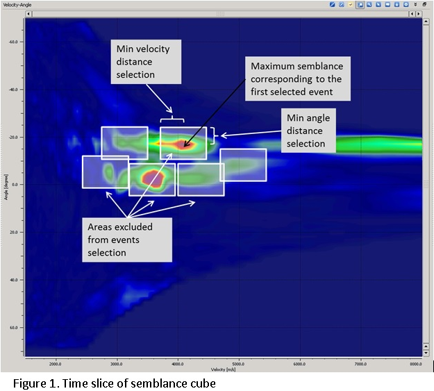
Min angle distance selection
Minimum distance in terms of semblance grid along angle axe, between events selected for summation. Parameter gives possibility to separate events with different correlation by angle (Figure 1).
•Default: 1
•Range: 1 - 100
Sets the minimum separation (in semblance grid cells along the angle axis) between distinct events selected for summation. This prevents multiple semblance peaks that are very close in angle from all being summed together as separate events, which would cause over-stacking. Increase this value when the semblance grid has a fine angle sampling and events from adjacent dip angles should not both contribute to the same stack sample.
Min radius distance selection
Minimum distance in terms of semblance grid along velocity axe, between events selected for summation. Parameter gives possibility to separate events with different correlation by velocity (Figure 1).
Default: 100
Range: 1 - 100
Sets the minimum separation (in semblance grid cells along the velocity axis) between distinct events. This prevents closely spaced velocity peaks from all being included as separate events. A value of 100 (the default maximum) effectively means only the strongest velocity event at each sample location is selected. Reduce this value if multiple velocity layers that are spectrally close in velocity must both be stacked.
Testing
This parameter group contains advanced settings that control how seismic trace positions are used, the spatial search aperture, and the time-shift method applied during imaging. These settings are typically used for testing or fine-tuning the imaging quality and are usually left at their default values for standard processing.
Use Trace headers
When enabled (default), the module reads source and receiver coordinates from the seismic trace headers when computing the MF time corrections. Disable this option only if the trace headers are absent or unreliable, and the module should rely solely on the geometry stored in the MF database. Default: true.
Max Distance To MF CMP
The maximum lateral distance (in metres) within which a raw seismic trace can be associated with an MF CMP location for imaging. Only traces within this radius of a given MF CMP are used to create the stack at that location. Default: 50 m. Valid range: 0–2000 m. Increase this value for sparse data or when the trace spacing is larger than the MF CMP grid spacing.
Interpolation Window Length
The half-length of the time window (in seconds) used to interpolate event time-shift corrections when applying MF moveout. Default: 0.010 s (10 ms). Valid range: 0–1000 s. A larger window smooths the applied shifts over a broader time interval, which can reduce high-frequency stretch artefacts at the cost of temporal resolution.
Stabilization Window Length
The half-length of the stabilization time window (in seconds) applied to suppress rapid oscillations in the time-shift field. Default: 0.010 s (10 ms). Valid range: 0–1000 s. Increasing this value produces smoother moveout corrections that are less sensitive to outlier events, but may blur the correction in time.
Shift Type
Selects the algorithm used to apply the MF time-shift correction to each trace. Available options:
Shift use windows (default) — Applies the correction using a sliding window approach, which provides a smooth and stable result for most data types.
Shift use stretching — Applies the correction by stretching the trace in time, similar to NMO correction. May introduce amplitude distortion (stretch mute) at large moveouts.
Shift use windows only on extremes — A hybrid method that uses stretching in the central portion of the trace and windowed shifts only near the edges of the time range.
Visualization
Apply following filters on sections and velocity semblance, for visualization only
This parameter group controls display-only corrections applied to the interactive stack section and semblance panels. These settings affect what the user sees on screen during picking but do not change the data written to output. Adjust them to make picking easier, particularly in areas with significant surface topography.
Datum
Value of final (flat) datum
Default: 0;
The elevation (in metres) of the flat reference datum to which the section is shifted for display. This is used when Shift To Datum is enabled. Set this to the desired output datum elevation — typically the same value used in the statics correction workflow for this project.
ShiftToDatum
Turn ON/OFF shift to final (flat) datum
Default: false;
When enabled, the displayed stack section is shifted to a flat datum level specified by the Datum parameter (Visualization group). Enable this option when working with data that has topographic relief, so that the interactive stack appears flat and is easier to interpret during picking. This shift is for display only and does not affect the exported output.
VelocityAGC
The time window length (in seconds) of an automatic gain control (AGC) function applied to the velocity semblance display. Default: 0.6 s. A longer window produces a more uniform semblance display across the entire time range, making it easier to identify velocity trends at both shallow and deep levels. Reduce this value to preserve the true relative amplitude of the semblance spectrum. This parameter affects display only and does not change the stacking result.
Types
Types of MF parameters to be created during imaging, created both vista item for visualization and gather
This group controls which MF attribute sections are computed and written to output. Enabling an attribute creates both an interactive display panel and the corresponding output gather. Only enable the attributes you need, as computing many sections simultaneously increases processing time. The Stack section is always recommended; attribute sections such as Correlation, Angle, and the velocity parameters are useful for QC and for subsequent depth conversion or inversion workflows.
Stack
Create zero offset MultiFocusing stack section
Default:true;
The primary output: the zero-offset MF stacked section assembled from events whose MF parameters fall within the user-picked velocity corridor. This is the main deliverable of the imaging module and should almost always remain enabled.
Correlation
Create MF correlation section
Default: false;
Produces a section showing the semblance (waveform coherence) of the best-stacking MF event at each sample. Values close to 1 indicate high coherence. Enable this for QC to identify where the stack is driven by well-focused events versus where it may be unreliable.
Angle
Create MF emergency angle section
Default: false;
Produces a section of the MF emergence angle parameter at each sample. This angle represents the apparent dip of the stacked reflector. Enable this output for structural QC or to feed dip information into subsequent depth conversion workflows.
Gamma
Produces a section of the gamma MF parameter, which describes the asymmetry of the wavefront curvature and is related to subsurface reflector geometry. Default: false. Enable this output when the gamma attribute is required for kinematic depth conversion or as input to the MF ZOMF tomography workflow.
CRE
Create MF CRE section
Default: false;
Produces a section of the Common Reflection Element (CRE) radius. The CRE radius characterizes the radius of curvature of the normal-incidence wavefront at the surface and is a key parameter for depth conversion. Enable this output when depth conversion using MF attributes is planned.
CRE2
Produces a section of the squared CRE radius. Default: false. This is an alternative form of the CRE attribute used in some kinematic inversion formulations where the squared parameter leads to a simpler linear relationship.
CRE Azimuth
Produces a section of the CRE azimuth angle. Default: false. This parameter is primarily relevant for 3D extensions of the MF method where the azimuthal direction of the CRE vector is meaningful. For standard 2D processing this output is typically not required.
CEE
Create MF CEE section
Default: false;
Produces a section of the Common Evolution Element (CEE) radius. The CEE radius characterizes the near-surface wavefront curvature and is used in conjunction with CRE for full MF depth conversion. Enable this when the CEE attribute is required for the depth conversion workflow.
CEE2
Produces a section of the squared CEE radius. Default: false.
CEE Azimuth
Produces a section of the CEE azimuth angle. Default: false. Relevant for azimuthal 3D MF extensions.
V Slow
Produces a section of the slow MF stacking velocity (VSlow), in m/s. For a 2D profile this corresponds to the NMO velocity in the inline direction. Default: false. Enable this output when the velocity section is required for depth conversion or for comparison with conventional velocity analysis results.
V Fast
Produces a section of the fast MF stacking velocity (VFast), in m/s. Default: false. VFast is orthogonal to VSlow and is primarily used in 3D MF analysis. For a 2D project, this parameter may not carry additional information beyond VSlow.
Dip
Produces a section of the reflector dip angle derived from the optimal MF parameters. Default: false. Enable this for structural interpretation or to use dip information in dip-guided processing steps.
Azimuth Dip
Produces a section of the dip azimuth angle. Default: false. Primarily relevant for 3D MF analysis.
VSlow / cos(Dip)
Produces a section of the dip-corrected velocity VSlow / cos(Dip), in m/s. This quantity approximates the true vertical velocity at a dipping reflector and is the recommended velocity parameter for time-to-depth conversion in structurally complex areas. Default: false.
VFast / cos(Dip)
Produces a section of the dip-corrected velocity VFast / cos(Dip), in m/s. Default: false.
Fold
Create MFfold section
Default: false;
Produces a section showing the number of MF events summed at each output sample. Useful for quality control: areas with low fold (few events contributed) indicate sparse coverage or strong velocity corridor filtering. Compare the Fold section against the Stack section to identify potentially unreliable stack areas.
Export Params
This parameter group controls how the MF attribute sections are written to the output SEG-Y files. These settings apply to the final export triggered by the Export params to sgy action.
Write mode
Default: direct;
Values: direct, append;
Controls how the output SEG-Y file is written. Direct (default) overwrites the output file from scratch at the start of export. Append adds new data to the end of an existing output file. Use Append when exporting results from different lines into a single concatenated file.
Convert To Feet
Convert output measurement system to feet
When enabled, velocity and distance attribute values are converted from metres (the internal unit) to feet before being written to the output SEG-Y. Enable this option when the project uses imperial units. Default: false.
No Zero Values For Velocity
Fill samples with zero velocities with V 0
When enabled, any output sample in the velocity sections (VSlow, VFast, etc.) that would otherwise be written as zero (due to no stacked events at that location) is replaced by the reference velocity V0 instead. This prevents zero-velocity gaps in the exported velocity model, which could cause problems in downstream workflows that interpret zero as a missing value. Default: false.
Zero padded
Fill traces with zero fold (non calculated) with zeros and write them to the output. Otherwise this traces are not written to output SEG-Y
When enabled, CMP locations where no MF events were computed (zero fold) are still written to the output SEG-Y as zero-amplitude traces. This keeps the output file geometrically regular (one trace per CMP), which simplifies subsequent loading into interpretation workstations. When disabled, zero-fold CMPs are omitted entirely from the output, resulting in a smaller file but potentially irregular geometry. Default: false.
Shift to datum
Shift exported results to final (flat) datum
Default: false;
When enabled, the exported output sections are shifted to the flat datum elevation specified by the Datum (Export Params) parameter before being written to the SEG-Y file. Enable this when the final deliverable section is required at a flat datum, as is common practice for prospect-ready deliverables.
Datum
Value of final (flat) datum
Default:0;
The elevation (in metres) of the flat datum to which the exported sections are shifted, when Shift to datum (Export Params) is enabled. Typically set to the same project datum used in the static correction workflow.
Band-pass
This parameter group defines an optional trapezoidal band-pass filter applied to the output sections. When enabled, the filter suppresses frequencies below F1, applies a cosine taper between F1–F2 (low-cut ramp), passes frequencies between F2–F3 at full amplitude, and applies a cosine taper between F3–F4 (high-cut ramp), rejecting frequencies above F4. This filter is applied to the exported SEG-Y output only and does not affect the interactive visualization.
Use
Turn ON/OFF band pass filter
Default: false;
Enable to apply the band-pass filter defined by Frequency 1–4 to the output data. When disabled (default), no frequency filtering is applied and the data is exported at full bandwidth.
Frequency 1
Default:1
The low-cut start frequency of the band-pass filter, in Hz. Frequencies below this value are fully attenuated. Default: 1 Hz.
Frequency 2
Default:5
The low-cut end frequency of the band-pass filter, in Hz. Frequencies between F1 and F2 are tapered from zero to full amplitude. Default: 5 Hz. Set F2 to just above the lowest signal frequency present in the data.
Frequency 3
Default:100
The high-cut start frequency of the band-pass filter, in Hz. Frequencies between F2 and F3 pass at full amplitude (the passband). Default: 100 Hz. Set F3 to just below the highest signal frequency in the data.
Frequency 4
Default:105
The high-cut end frequency of the band-pass filter, in Hz. Frequencies between F3 and F4 are tapered from full amplitude to zero, and frequencies above F4 are fully attenuated. Default: 105 Hz.