Attenuate spikes and high amplitude noise
![]()
![]()
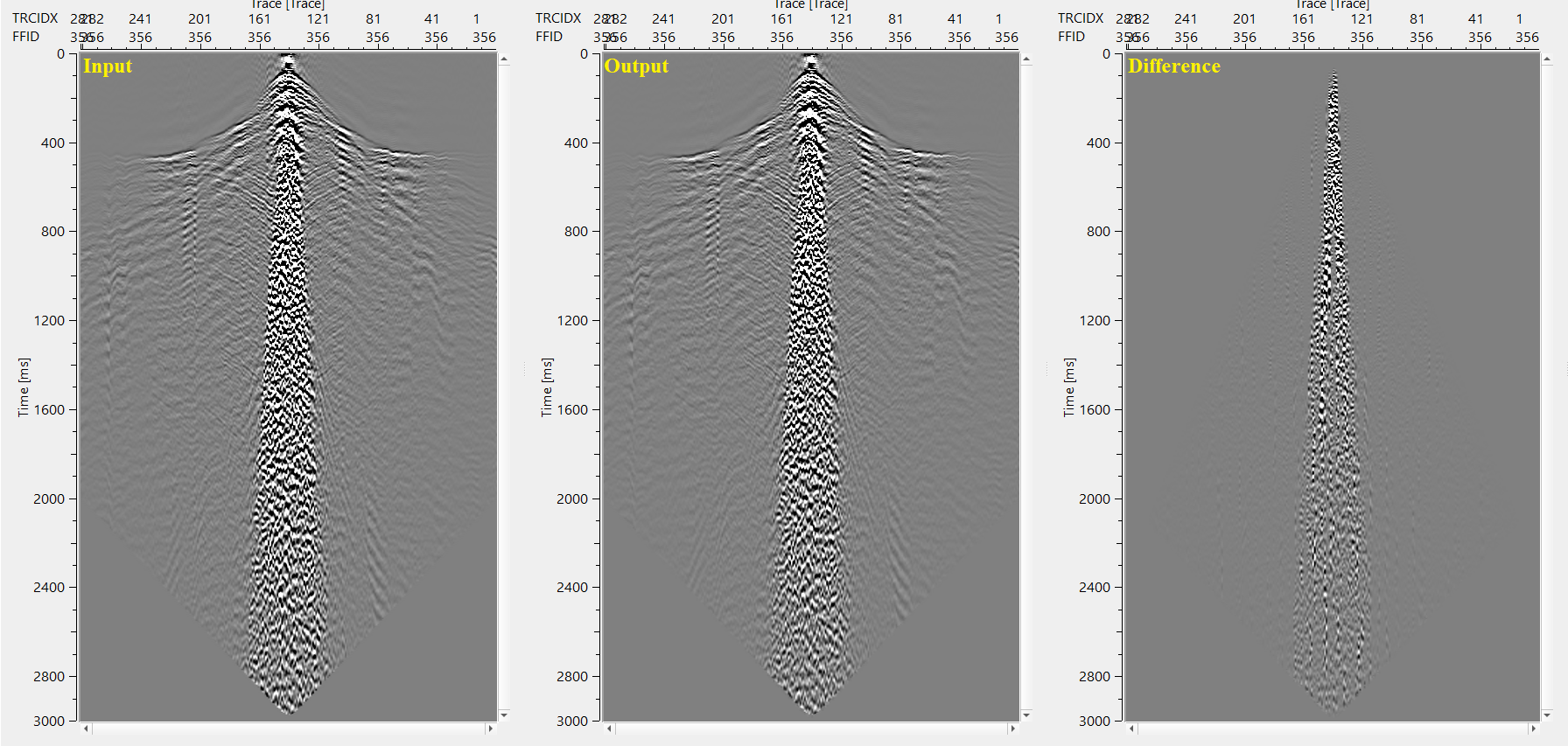
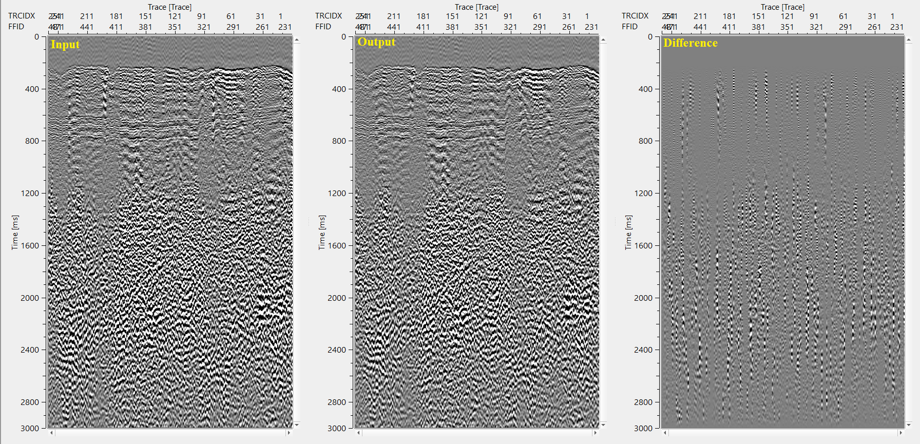
Despike module allows the user to remove amplitude spikes (high amplitude values that are many times larger than adjacent values) from seismic traces. Spikes are not normal seismic signal, they are usually created by the recording equipment and hence should be removed. Spike identification and removal is based on the average (depending on the chosen parameter) amplitude calculated in a time window and spatial window for each sample of the seismic trace in accordance with chosen threshold coefficient.
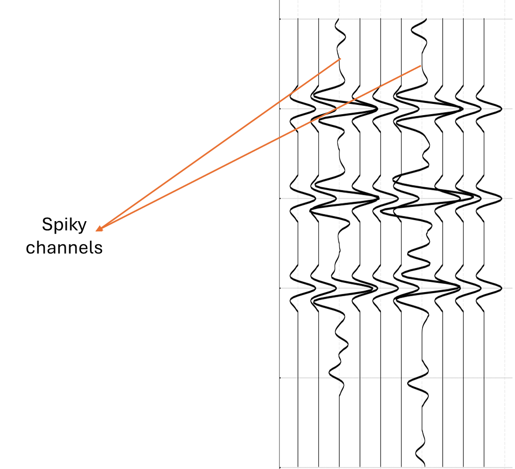
When there are higher amplitude spikes appear in a seismogram, based on the sliding window and time window values, the window moves both horizontally (spatial) and vertically (temporal) and checks for the higher amplitudes based on the user defined threshold value. If that particular amplitude value within in the sliding window is falling below or equal to the user defined threshold value, it moves to the next sample based on the threshold method (median, lower quartile, regression). If this value is higher than the user defined threshold value, it will either make it equal to the neighbor trace amplitude value or nullify it.
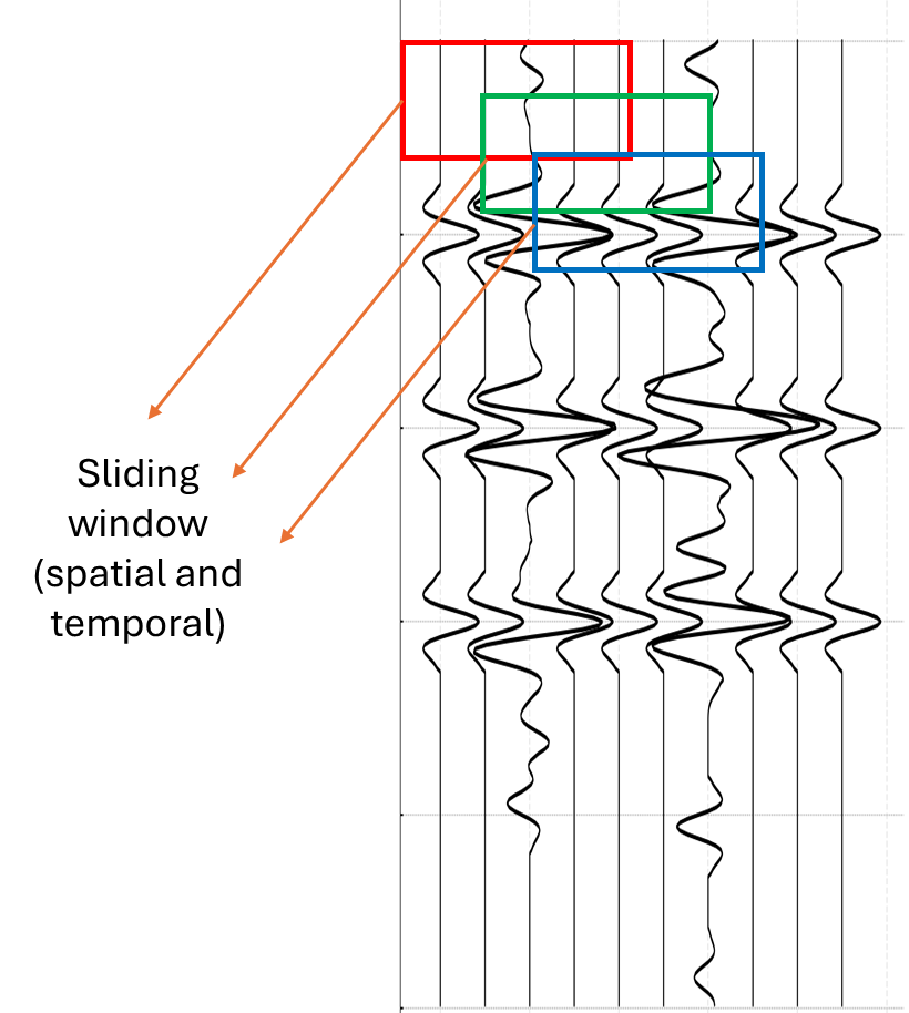
In the above image, if the horizontal window (traces) is defined as 5 traces( traces 1 to 5) and time window as 120 ms ( 0 to 120 ms) then the sliding window will consider the first 5 traces within 120 ms and look for the amplitude values. It checks the amplitude values with the user specified threshold value and if the amplitude values for each sample within the defined window is larger than the user defined threshold value, it will attenuate that sample and move towards the next trace. In this instance, it will move to the next trace i.e., 2nd trace and consider 5 traces (traces 2 to 6) as horizontal window and the vertical window remains same as 120 ms. This process continues till it reaches the last trace and then move down to the next vertical window starting from 121 ms to 240 ms etc. The acceptance and/or rejection of the amplitude threshold value depends on the threshold criterion method i.e. Median, lower quartile or regression.
![]()
![]()
Input DataItem
Input gather - input gather can be any one of the shot/receiver/cmp gather with higher amplitudes spikes.
![]()
![]()
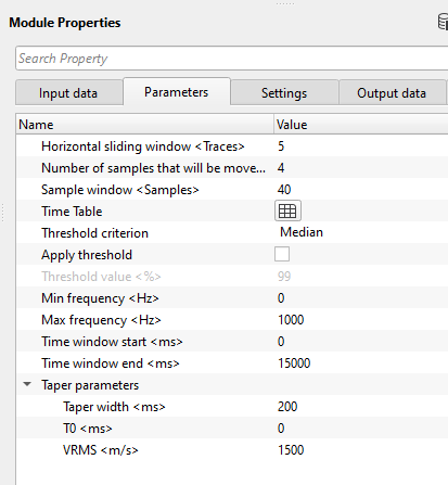
Horizontal sliding window - number of traces to include in the amplitude calculations.
This parameter controls the spatial extent of the detection window: the module looks at this many traces on each side of the current trace when estimating the background amplitude level. A wider horizontal window gives a more robust noise estimate but may smear lateral amplitude variations. Default: 5 traces (half-width). Use a value of 1 to restrict detection to the immediate neighbors, or increase it when spikes are isolated and the surrounding traces are clean.
Number of samples that will be moved - number of samples of the seismic trace that are feasible for suppression
This value sets the step size (in samples) by which the vertical analysis window advances through the trace. It must be an odd number (the module automatically increments an even value by 1). It must also be smaller than the Sample window. Default: 10 samples. Smaller values give finer resolution but increase processing time; larger values are faster but may miss short-duration spikes.
Sample window - number of samples to include in the amplitude calculations
The vertical (temporal) half-window, in samples, over which the reference amplitude level (median, lower quartile, or regression) is computed at each detection step. Default: 40 samples. A larger sample window produces a smoother, more stable reference amplitude but reduces sensitivity to short spikes. The sample window must be larger than the Number of samples that will be moved; otherwise the module returns an error.
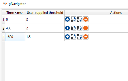
Time Table - amplitude calculation type to use in the requested time/space window. Inside the time table, the user should provide the time and threshold values. It can be a single time with a single threshold value or it can be time variant with different threshold values.
The Time Table is a collection of (Time, Threshold) pairs that define a time-variant spike detection sensitivity. At each time, the threshold multiplier controls how many times larger than the reference level (median, lower quartile, or regression) an amplitude must be before it is classified as a spike. The module sorts the entries by time and applies each threshold from its specified start time until the next entry begins. At minimum, one row must be present. Default: one row with Time = 0 s and User-supplied threshold = 3.
In case the user don't want to apply a harsher parameters in the shallower region, it can be done by providing an higher threshold value.
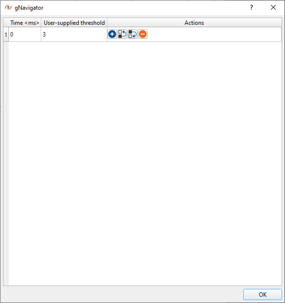
Time - specify the start time against the user-supplied threshold value. This threshold value will be applicable from this time. By default, 0. If this the default time is 0 ms and there are no other time - user supplied threshold pairs are provided then it will apply the same threshold value to the entire trace with user specified Time window end (ms) parameter.
User supplied threshold - this value/coefficient is the maximum amplitude value should be considered. Beyond this value, it consider as spike/higher amplitude and attenuates it.
Threshold criterion { Median, Lower quartile, Regression } - threshold is a useful parameter to differentiate the normal amplitude and higher amplitude spikes. Choose the threshold criterion from the drop down menu.
This setting determines how the module computes the reference (expected) amplitude level within the sliding window. A sample is flagged as a spike when its amplitude exceeds this reference level multiplied by the user-supplied threshold. Default: Median.
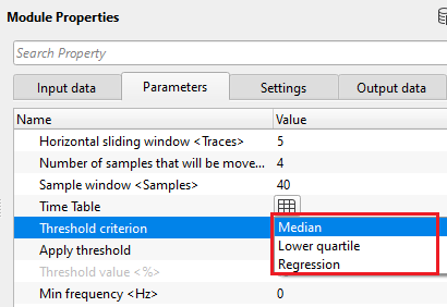
Median - this method works like arranging all the amplitudes from lower to higher values then considers the middle value. If the samples are odd numbers, it will consider the middle value. In case the samples are even numbers then it takes the two number from the middle of all the values and do an arithmetic average and considers that value as median value. Based on the median value, the module checks each and every sample and do the despiking.
Median is the most commonly used and recommended choice. It is robust to outliers by construction, making it well-suited for data that already contains a small number of extreme spikes.
Lower quartile - in this method, it considers the bottom 25% (quarter) of the whole samples and based on the sample values, it attenuates the higher amplitude spikes.
Lower quartile produces a more conservative (lower) reference level, meaning the same threshold coefficient will flag more samples as spikes compared to the Median method. Use this option when spikes are very frequent and the Median estimate is itself influenced by bad amplitudes.
Regression - it is a statistical modeling to find out the optimum threshold value.
Regression fits a statistical model to the amplitude distribution within the window to estimate the expected level. This option can be more adaptive to slowly varying amplitude trends across the gather, but is computationally more intensive than the Median or Lower quartile methods.
Apply threshold - based on the user specified threshold value, it decides whether input seismic trace is a normal or higher amplitude spike.
When enabled, an additional amplitude clipping pre-pass is applied to the data before the main despiking algorithm runs. This pre-pass clips the gather to a specified percentile level, removing the most extreme amplitude outliers first so they do not distort the reference statistics used by the main algorithm. Default: disabled (false). Enable this option when the data contains very large isolated spikes that would otherwise bias the median or regression estimate.
Apply threshold - true - By default, FALSE (Unchecked). If TRUE, it applies the user specified threshold value.
Threshold value - this is the maximum amplitude value that the user wants to considered as primary signal. Anything above this value is considered as higher amplitude or spike. Beyond this value, the module consider it as a spike and do the despiking.
This value is expressed as a percentile fraction (range 0.01 to 0.99). For example, a value of 0.99 clips amplitudes that exceed the 99th percentile of the absolute amplitude distribution in the gather, preserving the remaining 99% of samples untouched. Default: 0.99. Lower values apply more aggressive clipping; set to 0.95 or lower only when extremely energetic spikes are present that dominate the gather. This parameter is only active when Apply threshold is set to true.
Min frequency - specify the minimum frequency of the seismic trace that should be considered in the despiking process
The lower bound of the frequency passband applied to the seismic trace before the spike detection statistics are computed. Restricting the frequency band helps the algorithm focus on the frequency content of interest and avoid reacting to broadband noise. Default: 0 Hz (no low-cut filtering). Units: Hz. Valid range: 0 to 25000 Hz.
Max frequency - specify the maximum frequency of the seismic trace that should be considered in the despiking process
The upper bound of the frequency passband. Spikes are typically broadband (contain all frequencies), but setting an appropriate upper limit prevents the detection window from being dominated by high-frequency noise unrelated to true spikes. Default: 1000 Hz (effectively no high-cut for typical seismic data). Units: Hz. Valid range: 0 to 25000 Hz. Set this to a value near or slightly above the Nyquist frequency of your data to pass the full seismic bandwidth.
Time window start - define the starting time window to do the despiking
The start time (in seconds) of the trace segment to which despiking is applied. Samples before this time are passed through unchanged. Default: 0 s. Valid range: 0 to 100 s. Use this parameter together with Time window end to restrict spike suppression to a specific time interval, for example to protect the shallow zone or to focus processing on a target interval.
Time window end - define the ending time window to do the despiking
The end time (in seconds) of the trace segment to which despiking is applied. Samples after this time are passed through unchanged. Default: 15 s. Valid range: 0 to 10000 s. For typical 2D or 3D land or marine surveys with record lengths of 4–10 s, set this value to match or slightly exceed the maximum record length to ensure the entire usable trace is processed.
Taper parameters - taper parameters are helpful in smooth transitioning and avoid any kind of edge edges.
This group of parameters defines a hyperbolic blend zone near the top of the gather. Below the moveout curve defined by T0 and VRMS, each trace retains the original (input) amplitude unchanged. Above the moveout curve, the output is a linear blend between the original and the despiked amplitude, transitioning over a window of Taper width seconds. This protects shallow first-break energy, direct waves, and refractions from being altered by the despiking filter while still attenuating spikes in the deeper part of the record. This is exactly the approach illustrated in the example workflow that uses an LMO application before despiking.
Taper width - specify the taper width in milliseconds.
The duration (in seconds) of the linear blend transition zone above the hyperbolic mute curve. Over this interval, the output is gradually mixed from 100% original amplitude at the start of the taper to 100% despiked amplitude at the end. Default: 0.2 s (200 ms). A wider taper produces a smoother transition but delays the onset of full spike suppression. A narrower taper may introduce a visible boundary artifact if the despiked and original amplitudes differ significantly at the transition time.
T0 - mention the starting time value of the taper.
The zero-offset intercept time (in seconds) of the hyperbolic mute curve. At zero offset the taper begins at this time; at larger offsets the taper start moves later according to the NMO formula t(offset) = sqrt(T0^2 + offset^2 / VRMS^2). Default: 0 s. Set T0 to the two-way traveltime of the direct wave at zero offset (typically near 0 for land data) to protect the first-break region.
VRMS - specify the replacement velocity.
The RMS velocity (in m/s) used to compute the offset-dependent taper start time. This should be set to an appropriate near-surface velocity that approximates the moveout of the direct wave or refraction across the offset range of the gather. Default: 1500 m/s. For land data with a slower near-surface, use a lower value (e.g., 800–1200 m/s). For marine data, 1500 m/s (water velocity) is typically appropriate.
![]()
![]()
Auto-connection - By default, TRUE(Checked).It will automatically connects to the next module. To avoid auto-connect, the user should uncheck this option.
Bad data values option { Fix, Notify, Continue } - This is applicable whenever there is a bad value or NaN (Not a Number) in the data. By default, Notify. While testing, it is good to opt as Notify option. Once we understand the root cause of it,the user can either choose the option Fix or Continue. In this way, the job won't stop/fail during the production.
Notify - It will notify the issue if there are any bad values or NaN. This is halt the workflow execution.
Fix - It will fix the bad values and continue executing the workflow.
Continue - This option will continue the execution of the workflow however if there are any bad values or NaN, it won't fix it.
Calculate difference - This option creates the difference display gather between input and output gathers. By default Unchecked. To create a difference, check the option.
Number of threads - One less than total no of nodes/threads to execute a job in multi-thread mode. Limit number of threads on main machine.
Skip - By default, FALSE(Unchecked). This option helps to bypass the module from the workflow.
![]()
![]()
Output DataItem
Output gather - generates the output despike gather vector. It can be used as an input for next module or save it internally or externally.
Gather of difference - generates the difference display gather after despiking. This difference is between the input vs output gather.
There is no information available for this module so the user can ignore it.
![]()
![]()
In this example workflow, despike is used in combination with LMO (Linear Move Out) to avoid any primary leakage in the shallower part. Later we reverse back this Linear Move Out to bring it to it's original state. Despike procedure can be performed in any domain like common shot, common receiver or common depth point.
![]()
![]()
There are no action items available for this module so the user can ignore it.
![]()
![]()
YouTube video lesson, click here to open [VIDEO IN PROCESS...]
![]()
![]()
Yilmaz. O., 1987, Seismic data processing: Society of Exploration Geophysicist
 * * * If you have any questions, please send an e-mail to: support@geomage.com * * *