Calculating gain factor to scale the amplitudes
![]()
![]()
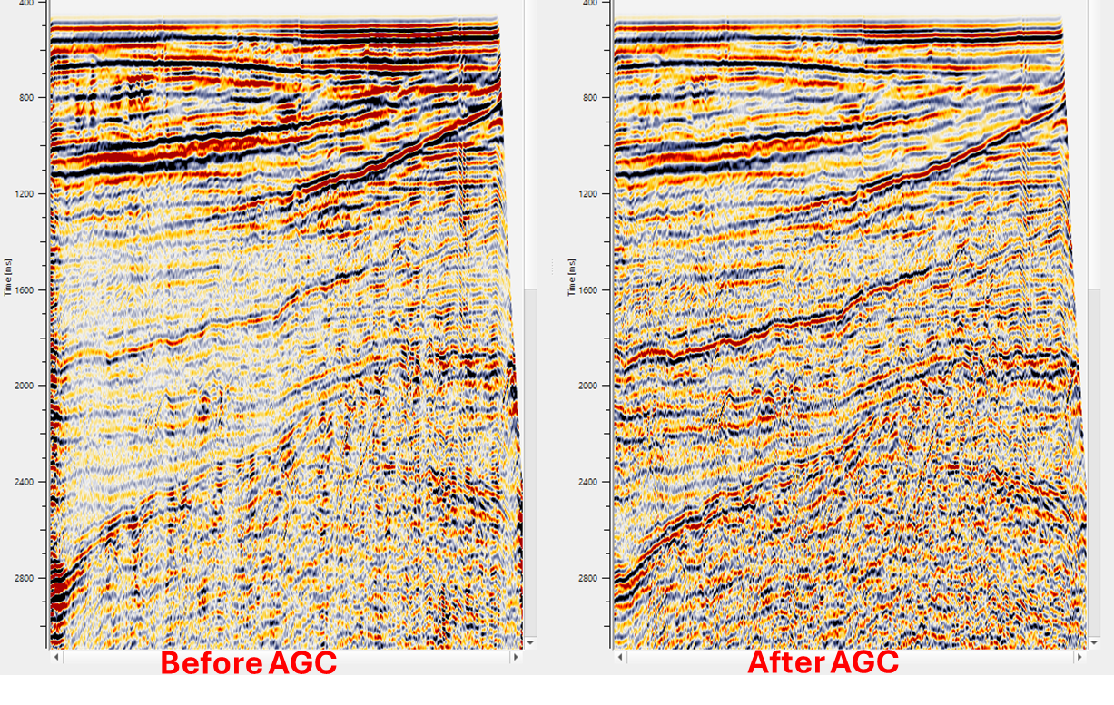
Amplitudes of the seismic data varies due to various factors like the sub-surface properties, source energy dissipation, source and receiver distance etc. Due to the scattering and attenuation of the amplitudes of the seismic data from top to bottom, it is not ideal for seismic data visualization and interpretation.To compensate the amplitude decay we apply an automatic gain control technique. It normalizes the seismic amplitudes and making them more easier to interpret and visualize.
This procedure is used for automatic trace scaling (automatic gain control) of input data.The model computes the average seismic trace amplitude within specified window.The calculated coefficient used to balance the data to constant amplitude.There is also a possibility to preserver the calculated coefficients for derivation of applied gain from the trace.
The purpose of AGC is to adjust the strength of seismic signals so that signals of different magnitudes can be analyzed more easily. It works by boosting weaker signals and reducing the intensity of stronger ones, allowing the entire dataset to be viewed and compared on a more consistent scale.
AGC is applied in different ways. Single window, Time variant and Exponential AGC.
Single window - It calculates the gain factor and normalizes the amplitudes within a user specified window by considering the maximum or average amplitudes.
Time variant - It adjusts the gain function dynamically with the time varying characteristics of seismic data
Exponential - It applies an exponential function to control the gain based on the amplitude variation over time.
Mathematically if we write the equation for the AGC,

G(t) or the Gain factor is calculated in various methods. For single window, it is based on the Root Mean Squared (RMS) sliding window method. In this, it calculates the rms or maximum amplitudes of the seismic signal/trace within the user defined window over a time "t".

![]()
![]()
Input DataItem
Input gather - connect/reference to the input gather. AGC can be applied to pre-stack data like shot/receiver/cmp gather as well as post stack data like stack sections.
![]()
![]()
AGC window - Specify the single window AGC value.
Use AGC gaussian taper - Gaussian function is used for weighed amplitudes calculation of each sample in specified window.
The weight of sample in center of window is “1” and “0” in edges.
Multichannel - By default, Unchecked. If it is checked, it will consider all the seismic channels within the gather and calculate the gain factor individually for each channel however it will boost the weaker signals and reduce/attenuate the higher amplitude signals.
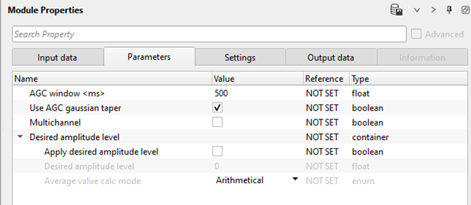
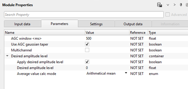
Desired amplitude level - In this section, the user can specify the desired amplitude levels of the seismic signal/trace.
Apply desired amplitude level - By default, unchecked. If it is checked, the user should specify the desired amplitude value in the next parameter. This is the reference or desired amplitude value for which the seismic traces are adjusted.
Desired amplitude level - By default, 0. Define the desired amplitude level of the seismic signal. Usually it is 1.
Average value calc mode { Arithmetical mean, Median } - Choose the methods to calculate the average value.
Arithmetical mean - It calculates the average value of the amplitudes by means of sum of all amplitude values of the seismic traces divided by total number of seismic traces.
Median - In this method, it calculates the average amplitude values by means of nth root of all traces are multiplied with each other.
![]()
![]()
Auto-connection - By default Yes (Checked)
Bad data values option { Fix, Notify, Continue } - This is applicable whenever there is a bad value or NaN (Not a Number) in the data. By default Notify. While testing, it is good to opt as Notify option. Once we understand the root cause of it, the user can either choose the option Fix or Continue. In this way, the job won't stop/fail during the production
Calculate relation - It calculates the amplitude relation and gives as an output.
Number of threads - One less than total no of nodes/threads to execute a job in multi-thread mode.
Skip - By default, No (Unchecked). This option helps to bypass the module from the workflow.
![]()
![]()
Output DataItem
Output gather - Outputs the AGC applied gather (shot/receiver/cmp) or stack section.
Amplitude relation - Outputs the amplitude relation
![]()
![]()
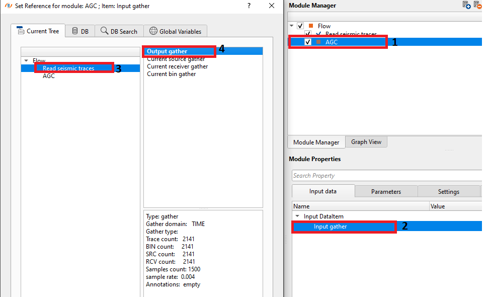
In this below example, we are reading a stack section using "Read seismic traces" and load data to RAM as Yes option. This data doesn't have any AGC applied. Now, we add AGC and reference/connect the Output gather from the "Read seismic traces" module to AGC.
![]()
![]()
There are no action items are existing for this module so the user can ignore it.
![]()
![]()
YouTube video lesson, click here to open [VIDEO IN PROCESS...]
![]()
![]()
Yilmaz. O., 1987, Seismic data processing: Society of Exploration Geophysicist
 * * * If you have any questions, please send an e-mail to: support@geomage.com * * *