PSDM Imaging
Multi-tool for PSDM stage: Stack image in depth and time domains, velocity analysis (DM picking for tomography), gathers and stacks depth to time conversion, horizon picking, horizons & well QC, RMO picking and applying.
Theory
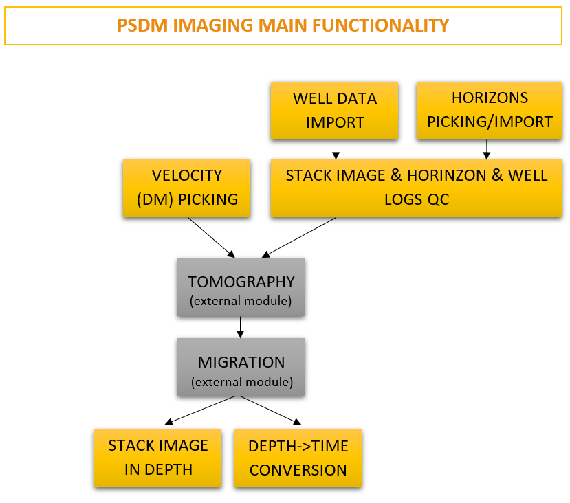
The PSDM Imaging Module is a comprehensive seismic imaging and velocity model refinement tool that integrates multiple functionalities essential for accurate depth migration and subsurface characterization. This module provides an extensive suite of capabilities, allowing geophysicists to perform depth velocity analysis, horizon picking and well logs displaying, seismic gather conditioning, and final imaging within a single workflow in PSDM sequence.
Key Features and Functionalities:
- Depth (Interval) Velocity Analysis and Tomography Integration
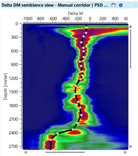
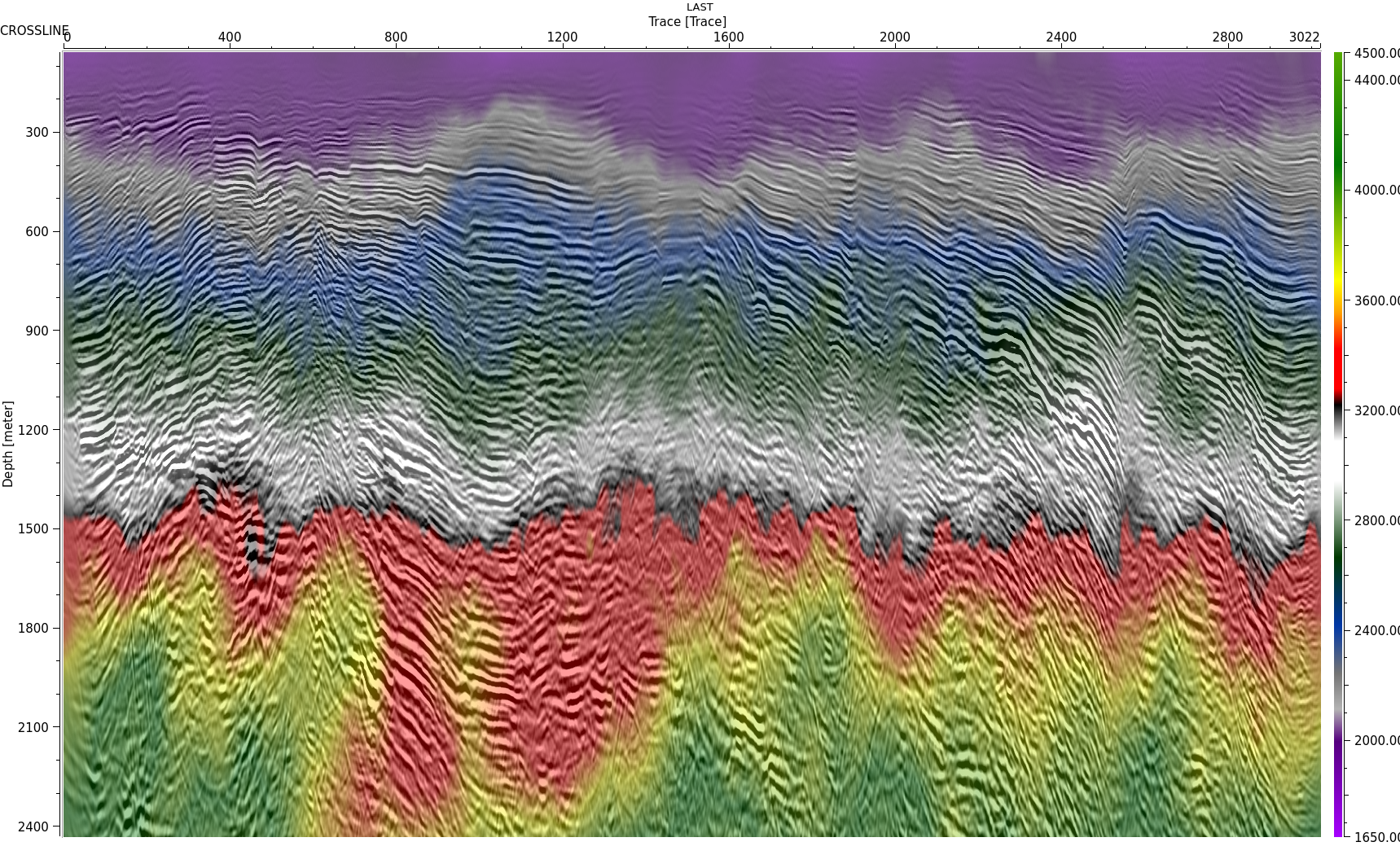
- Interval velocity analysis can be conducted interactively via DM picking, enabling users to refine their velocity model based on seismic gathers.
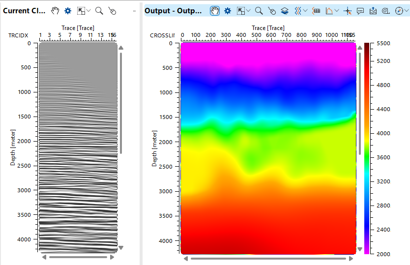
- The iterative velocity update process enhances the accuracy of seismic imaging, ensuring better subsurface interpretation.
- Common Image Gather (CIG) Processing and Conditioning
- Horizon and Geobody Modeling
- Depth-to-Time Conversion
- Optimized Preprocessing and Disk Space Efficiency
Workflow Integration:
The PSDM Imaging Module plays a critical role in the seismic imaging workflow, offering a structured process that includes:
- Data Input: Loading PreSDM Common Image Gathers for velocity analysis and processing.
- Velocity Model Update: Performing depth velocity analysis, picking delta misfits (DM).
- CIG Processing: Applying processing, internal and external mute picking, flattening gathers (RMO applying), and generating output CIGs (depth and time domains).
- Structural Interpretation: Horizon picking, geobody modeling, and well-tie integration.
- Final Imaging: Creating final stacks, performing depth-to-time conversion.
By leveraging these functionalities, the PSDM Imaging Module significantly enhances seismic imaging workflows, enabling geophysicists to achieve higher accuracy in subsurface imaging while optimizing computational resources.
Additional advantage of the PSDM Imaging Module is its ability to operate efficiently without generating excessive temporary files, reducing disk space usage. This is achieved through built-in preprocessing options that allow seismic gathers and stacks to be processed dynamically within the module, eliminating the need for external storage of intermediate datasets. The module's highly interactive interface supports real-time adjustments, ensuring optimal velocity model refinement and imaging accuracy.
Input data
Mandatory inputs:
Input SEG-Y data handle
seismic data after depth migration process, which will be used for velocity analysis (DM picking) or depth stack section creation.
Input data trace headers
trace headers of seismic data after depth migration process, which will be used for velocity analysis (DM picking) or depth stack section creation.
Depth velocity
interval velocity that was used for depth migration of the input seismic data set.
Optional inputs:
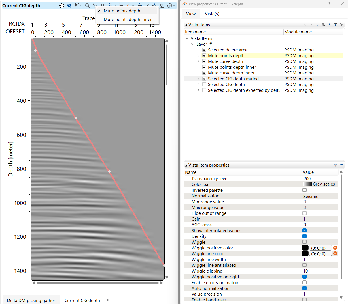
Mute picking item
possibility to use mute internal picking item from another PSDM imaging or import mute function via Load Item module and make connection the this Mute picking item parameter as an input mute. Internal muting function is used for semblance and stack calculation. Select Mute points depth via Set control button on the Vista's instrument panel:
 :
:
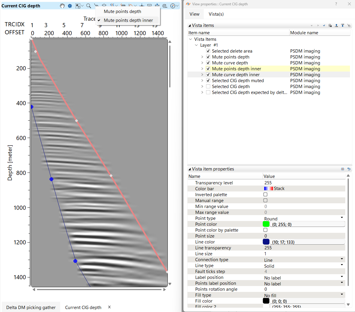
Inner mute picking item
possibility to use external mute picking item from another PSDM imaging or import mute function via Load Item module and make connection the this Mute picking item parameter as an input mute. External function muting function is used for semblance and stack calculation. Select Mute points depth inner via Set control button on the Vista's instrument panel:
:
Delta Vrms picking item
possibility to use to use Delta Vrms picking or import it via Load Item module and make connection the this Delta Vrms picking item parameter as an input mute. External muting function.
Delta Vrms corridor picking item
possibility to use to use Delta Vrms picking or import it via Load Item module and make connection the this Delta Vrms picking item parameter as an input mute. External muting function.
Remote time processing
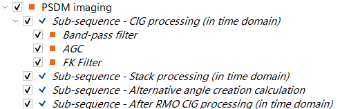
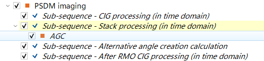
optionally there is an opportunity to use distribution (parallel) mode for sub-sequence calculation,  and for angle stacks calculation. For example if we need to apply some processing for CIGs or for the stack section we can put necessary modules inside the Sub-sequence:
Output file name stack angles
in case Remote time processing option is enabled this field is used to define a name for an output angle stacks data set.
Parameters
Execute options: particular options for execution, so the following outputs will be available from the PSDM Imaging. For example, if it requires only stack calculation we can enable only Create stacks option and save time for calculation.
Create stacks
module calculates stack section (full-stack) and angle stacks (in case Remote time processing is enabled as well).
Auto pick bins - based on the automatic picking parameters of DM module will perform auto-picking for all the bins.
Import horizons from item - an option for make an item connection in the workflow from Load Item module or other modules that have output horizon item.
Current horizon - if there is available horizon, this filed displays the current one.
Output time ratio - specify the output time ratio of output time image gather.
Output time length - specify the output time length of output time image gather.
V0
provide the near surface/replacement velocity.
Output datum - provide the output datum value in meters.
Use mute - Default it is TRUE. If the user picks any mute on the CIG gathers then it will applicable on the output gathers.
Use RMO - By default it is TRUE. If the user prefers to use this option Residual Move Out to correct the gathers.
Use super gather - By default TRUE. It is used in calculating the Delta Vrms semblance, therefore increasing quality of a semblance.
Super gather aperture - define the aperture by considering the bin center to the maximum offset range.
Normalize migration
there are three options of amplitude normalization for the input seismic gathers: none, 2D, 3D.
Accuracy - accuracy [Low, medium, High] of travel time table calculation, for example, if the TT table is more accurate then the time image gathers converted from the depth imaging gathers will be more accurate.
Stack creation bulk size - while creating the stack, it processes the number of traces in a bulk. Provide an appropriate bulk size. Default value works good enough.
Arbitrary line params : arbitrary line can be picked from the location map manually and it will be use for stacking.
Create arbitrary line - create/draw an arbitrary line on the location map and it will create the stack(s) of the arbitrary line.
Arbitrary line step - distance between the neighbor bins from the arbitrary line.
Map interpolation - The interpolation process is used when creating horizons, either through picking or importing:
Interpolation type
select one of two methods: Kriging or ABOS.
Kriging covariance - Defines the spatial correlation model used in Kriging. Available types: Spherical, Gaussian, and Exponential.
Kriging range <meters> - Specifies the range of influence for spatial correlation in the Kriging model. A larger range results in smoother interpolation, while a smaller range captures more local variations.
Kriging max points - Defines the maximum number of data points considered in the interpolation process for estimating unknown values. Increasing this value improves accuracy but may increase computation time.
Interpolation step X - Determines the grid resolution in the X direction for interpolating horizon maps. A smaller step size increases detail but requires more processing power.
Interpolation step Y - Defines the grid resolution in the Y direction for horizon interpolation. Like the X step, a finer resolution provides more detail but demands more computational resources.
Markers options
Marker accuracy - It is the distance between the neighbor bin and the well marker. If the distance between the bin and well marker is greater than the user actual value of the marker and the bin, this well marker won't attach to this bin. However if the distance is close to the well marker and neighbor bin, it will attach to the bin. Usually the bin grid size is sufficient enough for the marker accuracy to consider this well marker to the neighbor bin.
Smooth picking parameters - option for smoothing an output DM gather, for example to remove picking spikes or inversions:
Remove inversions from DM picking - use removing inversion on the DM field.
Type of inversion to remove - Negative or Positive.
Depth start <meters> - start depth value in meters for initial removing inversion.
Depth end <meters> - end depth value in meters for stop removing inversion.
Use smooth for DM picking gather
use smoothing of DM field.
Delta Vrms smooth X
smoothing distance in X direction.
Delta Vrms smooth Y
smoothing distance in Y direction.
Delta Vrms smooth Z
smoothing distance in Z direction.
Delta DM semblance params
: parameters for DM semblance creation and picking settings
Use super semblance
use or not super gather.
Use average semblance from bins of super gather - when the Super Gather option is selected, semblance is calculated based on the super gather aperture. This approach enhances semblance quality by averaging data over multiple bins, reducing noise in the semblance display. A larger super gather aperture helps suppress random noise, leading to a clearer and more reliable semblance representation.
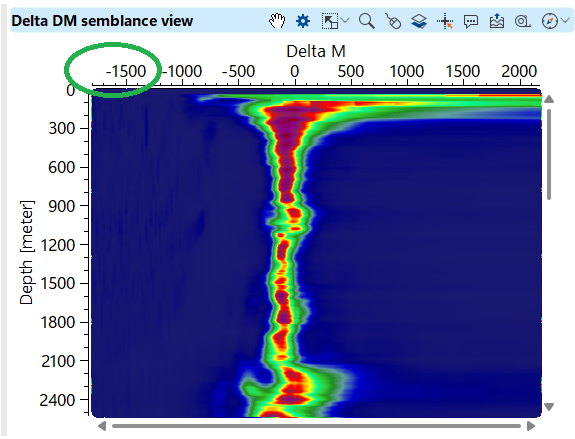
Delta Vrms min
Minimum delta Vrms value:
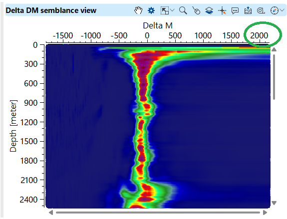
Delta Vrms max
Maximum delta Vrms value:
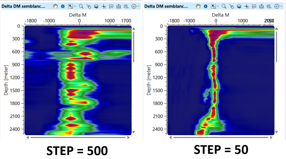
Delta Vrms step
Step value of delta Vrms:
Auto picking edge <meters> - edge area for skipping DM picking, because of low fold area is low S/N ratio.
Start auto-pick depth from topo - By default FALSE. If checked, DM auto picks will start from the topography.
Auto picking start depth - start depth position for auto picking delta Vrms option. Execution button also is available from the action items, as well as double click on the module will do Auto pick bins if it was enabled in the Execute options:

Auto picking end depth - end depth position for auto picking delta Vrms option
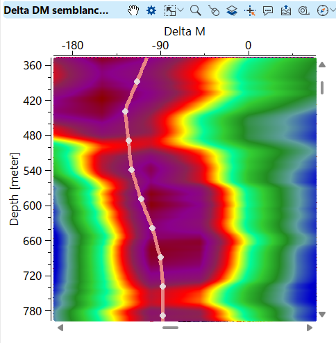
Auto picking depth step - depth interval the auto picking of delta Vrms should pick:
Auto picking inline step - define the trace step size to auto pick the delta Vrms along inline direction.
Auto picking crossline step - define the trace step size to auto pick the delta Vrms along crossline direction (CMP in case of 2D data).
Auto picking threshold - depending on the auto-picking depth step, the auto-picker selects the delta Vrms based on the specified threshold value. If the threshold value exceeds the semblance value, the auto-picker disregards those picks within the defined depth step.
Use corridor for auto picking - The user can pick the corridor and the auto picker will consider the semblance values in this corridor to pick the delta Vrms. The corridor works like constrain for auto picking:
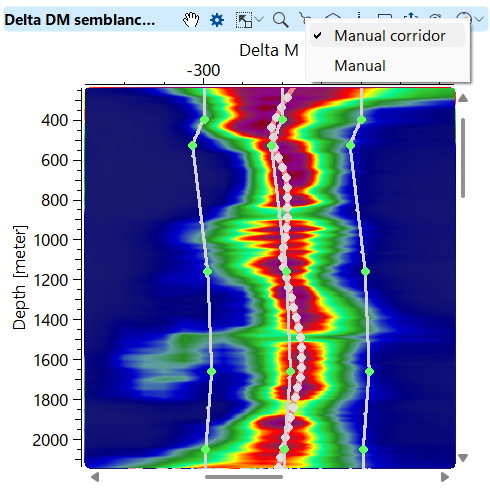
Corridor width on click - the distance from the picking position to both sides of the picking location of the corridor.
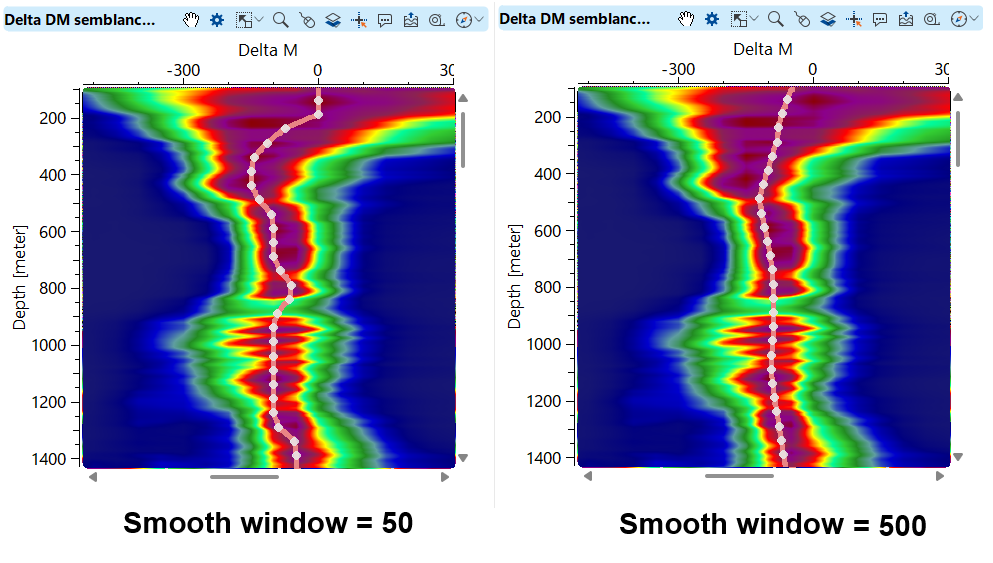
Use smooth for auto picking - provide the smoothing to the auto picking.
Smooth window for auto picking - The more the smooth window the result of the auto picks of the delta Vrms are smooth:
Limit residuals - If checked, an algorithm limits the residual of the time shift in the far offsets to a certain extent as defined by the user.
Max allowed residual on max offset - this value determines how much is the maximum shift allowed in the far offset.
Inversion tolerance for auto picking - By default it is FALSE. If the user checks this option it will calculate the inversion tolerance depending on the Delta V and Delta Z values.
It calculates the ratio of Delta V/ Delta Z for a line segment on the Delta Vrms auto picking semblance window. This ratio should be less than or equal to the Delta V/DeltZ ratio. The objective of this calculation is to avoid the zig-zag pattern of the auto picking.
Delta V - Provide Delta V value as per the semblance.
Delta Z
Specify Delta Z value.
Use semblance normalization - This option is disabled (FALSE) by default. When enabled, the overall semblance panel is divided into overlapping windows, with each window overlapping by half of its length. The maximum amplitude within each window is identified, and all samples within that window are normalized using this value. Finally, the normalized samples from all windows are averaged, producing a balanced and enhanced semblance display.
Semblance normalization window - Defines the interval at which semblance normalization is applied. This parameter determines the length of the overlapping windows used for normalization, influencing the smoothness and accuracy of the normalized semblance display.
Use semblance smooth
Smoothing of the semblance matrix.
Semblance smooth window - provide value for smoothing window for the semblance matrix
Super semblance parameters
: semblance will be calculated in accordance withing gather accumulation parameters:
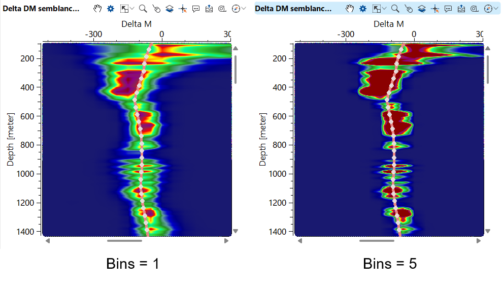
Multiplied super gather radius inline <Bins>
number of bins/gathers for super gather:
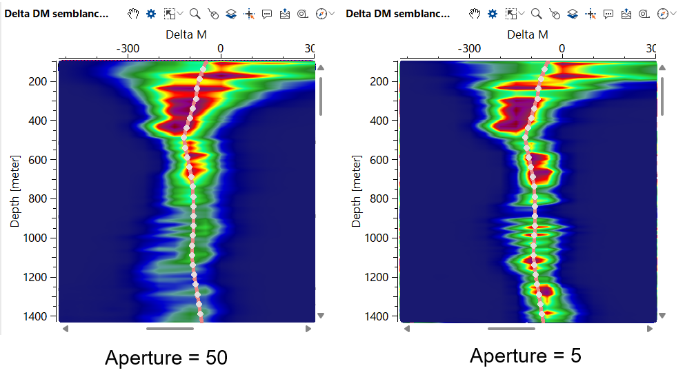
Aperture
distance in meters for gather accumulation:
Import horizons from ASCII params
additional option for horizon QC, or example is we have an ASCII file with horizons from interpreters and we would like to check horizons & stack image & well-tops; make overlaying of seismic image and well tops and horizons.
Input item horizons for input - possibility to make connection with Horizon (if it is already exist) item from Load Item module or another module that has an output Horizon item.
Location - specify whether the horizon is on Topography or Constant Datum.
Datum - if the location is Datum define datum value in meters.
Scalar - scalar for the depth coordinates if necessary (usually it's not).
Add constant shift time - add constant time shift in milliseconds to the horizon during importing.
Add constant shift depth - add constant depth shift in meters to the horizon during importing.
Other import parameters
:
Coordinate scalar
scalar for the coordinates.
Markers type - select MD or TVDSS:
MD (Measured Depth) – The actual length of the wellbore from the surface to a given point, accounting for all deviations and curvature.
TVDSS (True Vertical Depth Subsea) – The true vertical depth relative to sea level. It represents the vertical distance from the mean sea level (or another reference datum) to a specific point in the well.
Build maps on loading markers - scalar for the coordinates.
TT smooth
: smoothing parameters for ray path time table values
Smooth dx <meters>
smoothing along X direction (inline).
Smooth dy <meters> - smoothing along Y direction (crossline).
Smooth dz <meters> - smoothing along Z direction (vertical).
Angle stacks params
: parameters that are related to creation angle stacks
Current angle - this will display the current angle and the corresponding angle stack if the user generated the angle stacks from the action items "Recreate common angle stacks". This will display all the available angle ranges as it is specified in the below parameters.
First angle - starting angle value (degree) for angle stack.
Last angle - end angle value (degree) for angle stack.
Step angle
angle value (degree) step size.
Angle smooth window length - angle smoothing parameter in milliseconds to make angle function more or less smooth.
Alternative - by default it is FALSE however if the user checks this option, it will consider the Vrms velocities for creating the angle stacks.
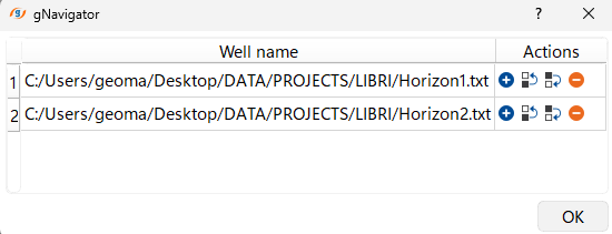
Wells
wells loading interface for importing ASCII files with well tops into the module and use it for QC:
Settings
SegyReadParams
parameters for setting advanced parameters of reading seismic traces from disk:
Thread count (for SSD)
amount of treads for reading seismic traces from disk.
Bulk size (traces)
size of a chunk (data portion) for reading seismic traces from disk.
Execute on { CPU, GPU }
- select which type of processor will be used for calculations: CPU or GPU.
Distributed execution
if enabled: calculation is on coalition server (distribution mode/parallel calculations).
Bulk size
chunk size is RAM in megabytes that is required for each machine on the server (find this information in the Information, also need to click on action menu button for getting this statistics):
Limit number of threads on nodes
limit numbers of of threads on nodes for performing calculations.
Job suffix
add an job suffix.
Set custom affinity
an axillary option to set user defined affinity if necessary.
Affinity
add your affinity to recognize you workflow in the server QC interface.
Number of threads
limit number of threads on main machine.
Run scripts
it is possible to use user's scripts for execution any additional commands before and after workflow execution:
Script before run
path to ssh file and its name that will be executed before workflow calculation. For example, it can be a script that switch on adn switch off remote server nodes (on Cloud).
Script after run
path to ssh file and its name that will be executed before workflow calculation.
Skip - switch-off this module (do not use in the workflow).
Output data
Stack inline time
seismic stack image along inline direction that was converted to time domain (from depth) via input velocity model.
Stack inline depth
seismic stack image along inline direction in depth domain.
Stack inline depth after time processing
seismic stack image along inline direction in depth domain with time processing from Sub-sequences (inside this module):
Inline V depth
interval velocity along inline.
Stack crossline time
seismic stack image along crossline direction that was converted to time domain (from depth) via input velocity model.
Stack crossline depth
seismic stack image along inline direction in depth domain.
Stack crossline depth after time processing
seismic stack image along inline direction in depth domain with time processing from Sub-sequences (inside this module):
Crossline V depth
interval velocity along crossline.
Stack Arbitrary time
seismic stack image along 2D arbitrary line that was converted to time domain (from depth) via input velocity model.
Stack Arbitrary depth
seismic stack image along 2D arbitrary line in depth domain.
Stack Arbitrary depth after time processing
seismic stack image along 2D arbitrary line in depth domain with time processing from Sub-sequences (inside this module):
Arbitrary V depth
interval velocity along 2D arbitrary line.
VRMS from interval cube
RMS velocity was calculated from interval velocity cube.
VRMS from interval datum inline
RMS velocity along inline that was calculated from interval velocity on the datum.
VRMS from interval datum crossline
RMS velocity along crossline that was calculated from interval velocity on the datum.
Selected CIG time expected by delta DM
1 selected CIG in time domain that is expected after DM correction. This is approximate gather, obviously that CIG after migration process will be a bit different in terms of kinematic and amplitudes.
Selected CIG depth expected by delta DM
1 selected CIG in depth domain that is expected after DM correction. This is approximate gather, obviously that CIG after migration process will be a bit different in terms of kinematic and amplitudes.
Selected CIG time
1 selected CIG in time domain that is input seismic, i.e. before DM correction.
Selected CIG depth
1 selected CIG in depth domain that is input seismic, i.e. before DM correction.
Selected CIG depth muted
1 selected CIG in depth domain that is input seismic (i.e. before DM correction) with mute function applied.
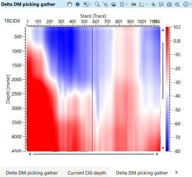
Delta DM picking gather
resulting DM filed in seismic format, after all smoothing if it was enabled. Therefore if it's necessary to save an original (raw) DM filed switch off smoothing and removing inversions.
Output horizons
horizons that were picked or imported in the module.
Angle stack inline
angle stack along inline.
Angle stack arbitrary line
angle stack along arbitrary line.
Angle stack crossline
angle stack along crossline.
Information
There is no any output information.
Actions
Clear mute picking
removes external or/and internal mute from the workspace.
Load mute picking
load mute picking from ASCII file (*.corr is internal g-Platform format).
Save mute picking
save mute picking to ASCII file (*.corr is internal g-Platform format).
--------------------------
Clear horizons - removes all loaded horizons from the workspace.
Save horizons binary
save horizon to binary file (internal g-Platform format).
Load horizons binary
load horizon from binary file (internal g-Platform format).
--------------------------
Import horizon ASCII - imports horizon data from an ASCII file (*.hor is internal g-Platform format).
Export current horizon ASCII - exports the currently selected horizon to an ASCII file (*.hor is internal g-Platform format).
--------------------------
Remove all markers
removes markers from the workspace.
--------------------------
Clear picking
clear delta Vrms picking and/or corridors.
Save picking
save horizon to ASCII file (*.hor is internal g-Platform format).
Load picking
load horizon from ASCII file (*.hor is internal g-Platform format).
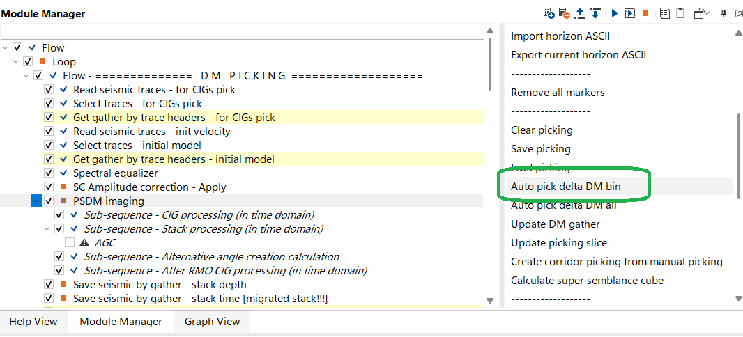
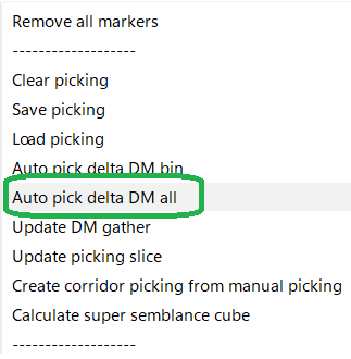
Auto pick delta DM bin - automatically picks delta DM values within a specific bin.
Auto pick delta DM all - automatically picks delta DM values across the entire dataset.
Update DM gather - updates the DM (Depth Model) gathers based on the latest picking.
Update picking slice - updates the picking data for the current slice.
Create corridor picking from manual picking -generates a picking corridor based on manually picked points.
Calculate super semblance cube - computes a super semblance cube for improved velocity analysis.
--------------------------
Create and save full stacks - generates and stores full seismic depth and time stacks.
Create output CIGs - pproduces Common Image Gathers (CIGs) in time domain and depth domain after time processing.
Recreate arbitrary line gather - regenerates gathers along a user-defined arbitrary line.
--------------------------
Recreate common angle stacks
generates angle stacks.
--------------------------
Import well markers V2 - imports well marker data in V2 format (*.hor is internal g-Platform format).
Rebuild maps for well markers
generates map for well markers.
--------------------------
Create average V maps
generate average velocity maps.
Examples
Main task is: DM picking (manual + auto) & stack creation in depth domain.
Workflow example, there are two input data sets: CIG after depth migration and interval velocity model for this migration:
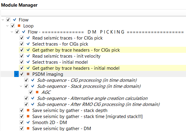
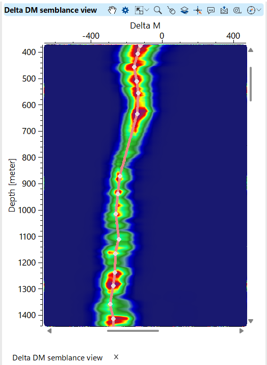
The entire list of parameters, but not all of them we need to define for current task (DM picking and stack creation). Delta DM semblance params tab is the main one for DM semblance and DM picking:

To display the vista items, the user should right click on the PSDM Imaging and select Vista Groups -> not all, but just minimum necessary, as in the example below:
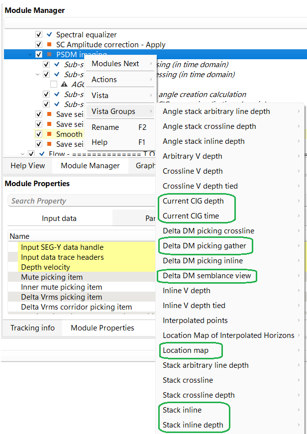
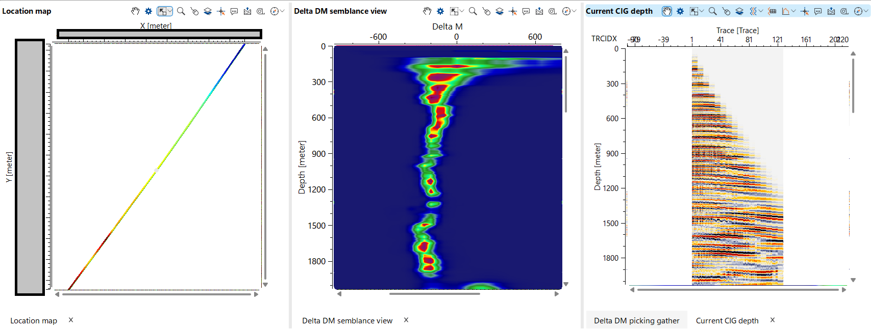
Location map, DM semblance and CIG depth gather (we can do QC picking via CIG time gather as well):
Make a corridor picking for auto picking limitation, it is not necessary to do very CMP (CIG) point, i.e. 50 CMP step is enough: 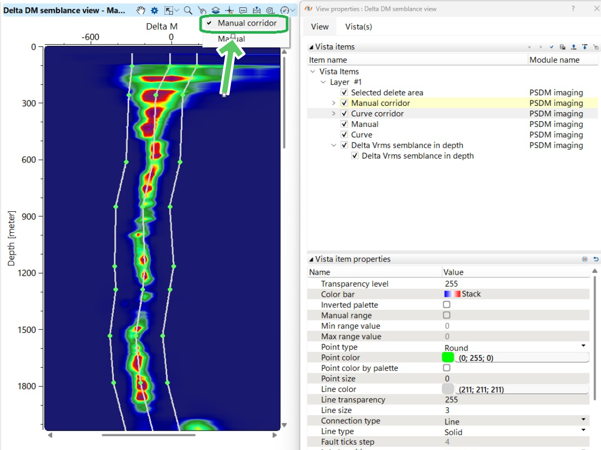
Then we need to test and tune auto picking on several CMP (CIG) points, select any CMP pount and lick on Auto pick delta DM bin button in the action menu as it's shown blow:
There will be a red colored curve live with DM picking:
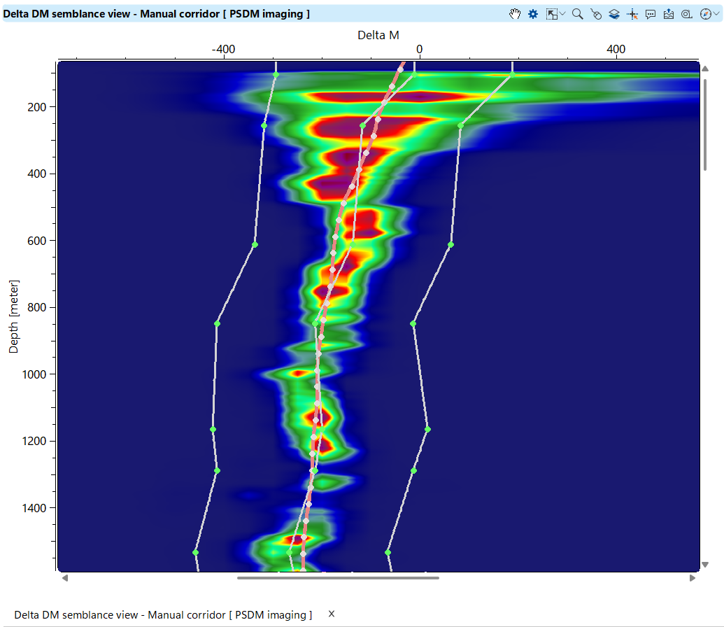
If DM picking is satisfiable press the next button Auto pick delta DM all for performing auto picking for the entire data set in accordance with defined parameters:
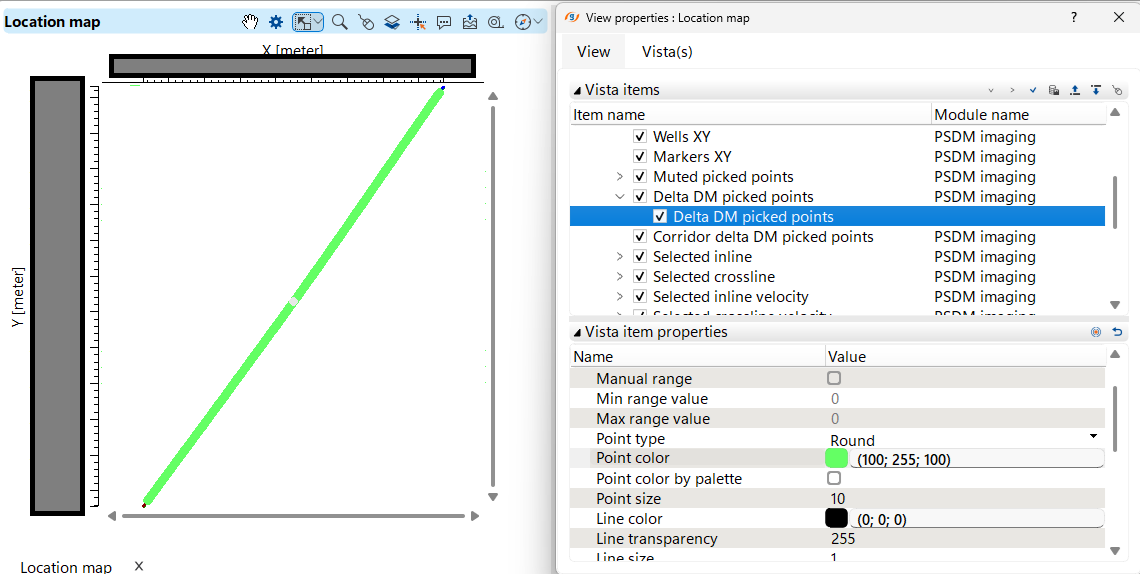
On the location map all picked points re highlighted with green color:
Delta DM gather QC:
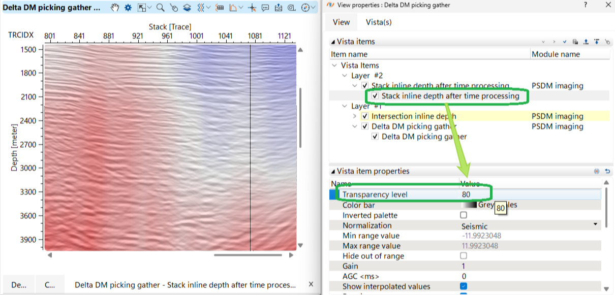
We can create overlay of Stack section + DM by drag'n'drop (via mouse) a stack section from the PSDM imaging:
a) mouse drag'n'drop:
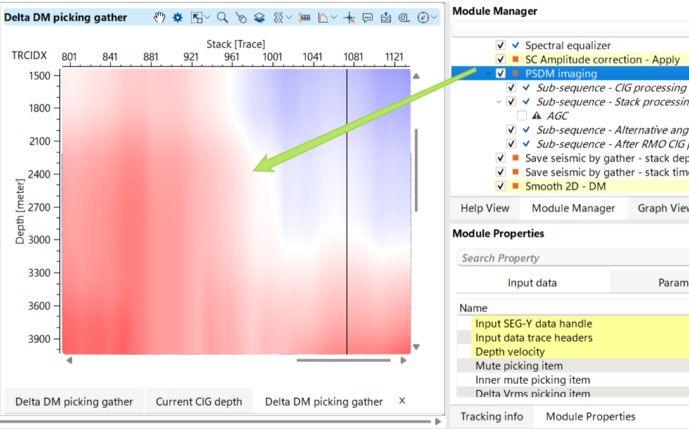
b) Stack selection:
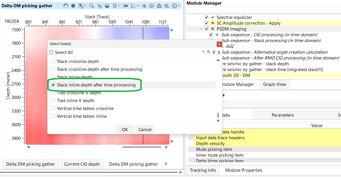
c) Transparency % of a Stack selection:
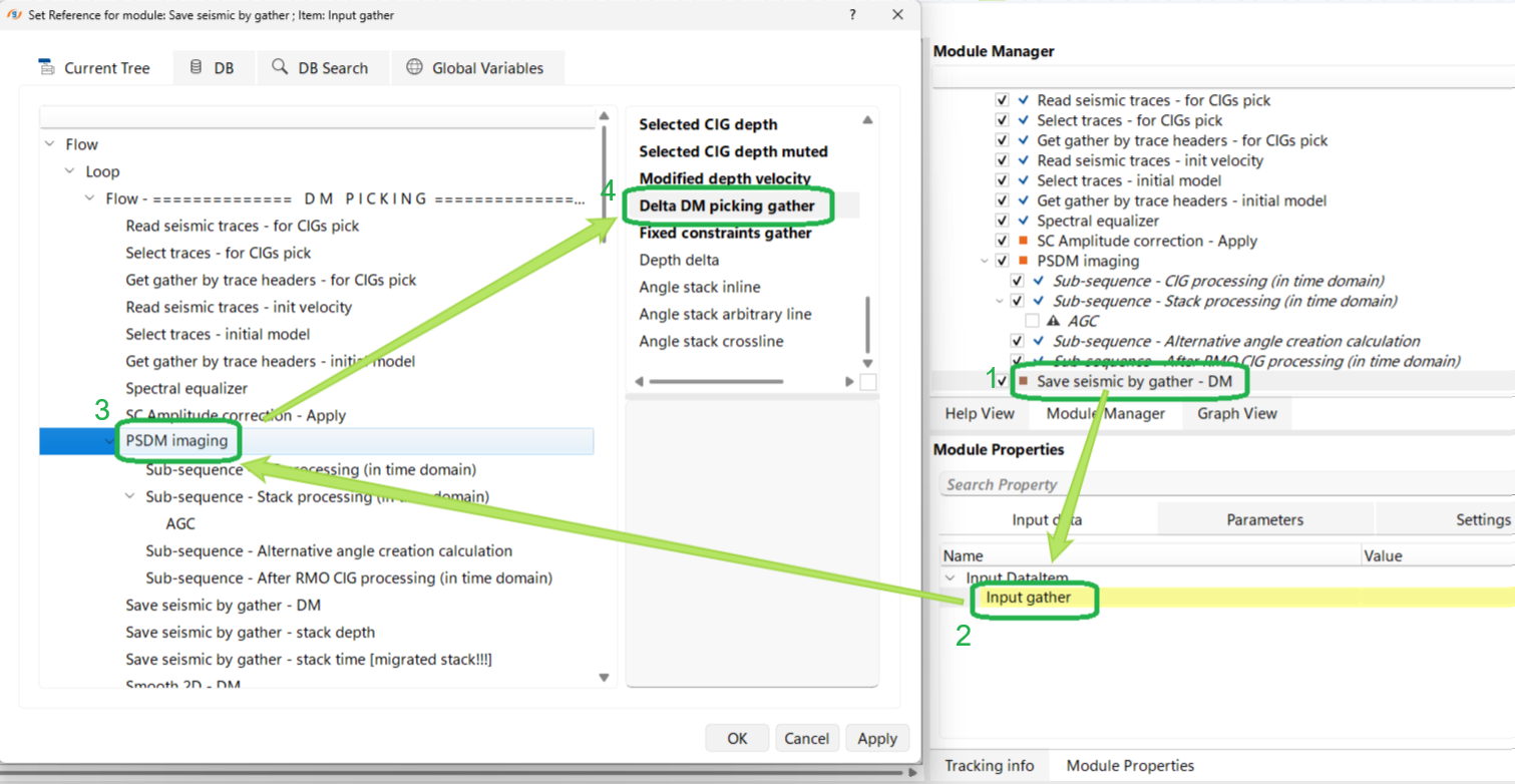
Next step is using DM gather in the tomography process (update velocity model) as input data set, therefore we can save DM gather via Save seismic by gather module or connect it directly to the tomography module Ray tracing velocity updater:
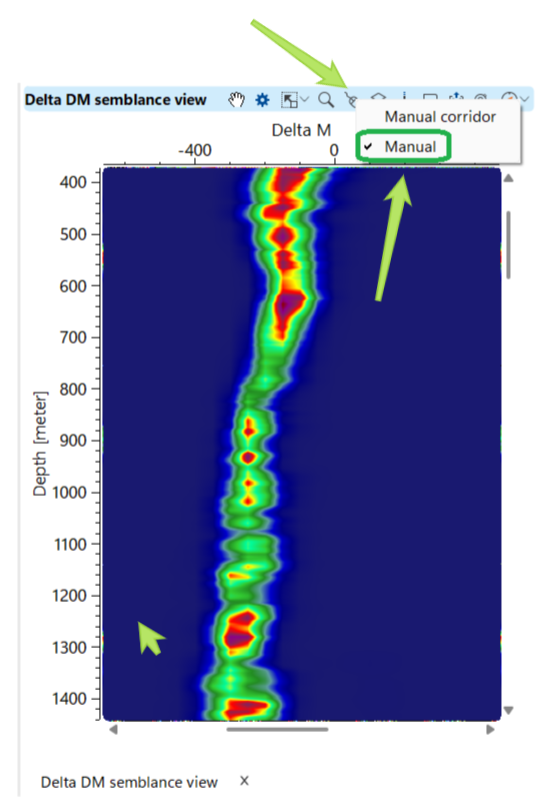
This DM gather was created by auto picking, but we can do manual picking as well, but it is not detailed or time consuming process. In the Delta DM semblance view select Manual action control and use mouse buttons for picking and erasing user DM picks:
Video lesson
YouTube video lesson, click here to open [VIDEO IN PROCESS...]
Related articles
 If you have any questions, please send an e-mail to: support@geomage.com