Description
PSTM Imaging Selector 2D (Velocity/Angle/Offset) module can be used for generating the PSTM Angle stacks, picking vertical Delta Vrms picks, Vertical Vrms velocity picks and Common Image Gathers.
This part of the help manual describes the functioning and generation of Enhanced angle stacks using Eraser/Enhancer tool.
Prior to use the module, user needs to have the input information in the form of storage file(.kdb) (which can be generated by using Velocity Selector-Kirchhoff PreSTM Engine) wherein user creates the PSTM stacks with different velocity factors (for example velocity ranges from 80% to 120% with an increment of 2% step size).
Input the Storage file in the “ Input data ” tab. Inside the Parameters tab user needs to assign Datum (meter) and other required parameters before start of the procedure. For Angle stack generation, user needs to input the “ Angle gathers parameters” to create the angle stacks within the user defined angle range. Once all the parameters are set, user have to generate the common angle gathers from the sub panel by clicking on the “ Recreate Common Angle Gathers ”. Then user needs to generate the angle stacks by selecting the option “ Create stack by angle gathers ” as shown in the figure below.

From the Vista items, user can add Reference Stack (PSTM Stack), Current CIG (to pick mute on Common Image Gather) and finally Angle Stacks.
Following is the processing flow to generate final enhanced angle stack.
Define the angle range and appropriate angle step to generate the common angle gathers
1.By selecting the create stack by angle gathers user can able to generate the individual angle stacks from the defined angle range.
2.Now scan through all the defined angle range and pick the mask mute.
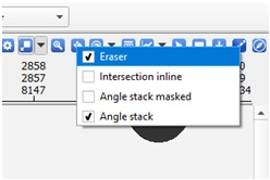
In order to pick the mask, user needs to select the Eraser option as shown below besides selecting the Angle Stack option. We also have the Angle stack masked which is helpful in finding out where the changes were made. So it’s easy to track the changes made to the individual angle stack.
Working with Eraser/Enhancer tool:
By using mouse wheeler, one can scan through all the angle stacks without much effort. Once user scanned through all the individual angle stacks, user is ready to pick the angle mute mask. To pick the angle mute mask, user has to select the Eraser tool on the Angle stack display and hold Shift+MB1 button to enhance or highlight the area of the interest. At any point of time, if user wants to change the mute mask, user can do so by holding the Shift+MB3 button to erase the mute mask at that particular area. At given point of time if user wants to delete/remove the noisy sections of the angle stack, it can be done by simply holding the MB1 and it will remove.
After scanning through all the individual angle stacks and picking the angle mute, user have to save the angle mute mask using “ Clear/Save/Load Mask” option from the sub panel as shown below.

Finally user can generate the Enhanced angle stack from the picked angle mute mask. To get the final stack, select the “ Final angle stack” from the Vista items.
Note: From the Current Velocity Factor in the Parameters tab, user can toggle between different pstm stacks with different velocity factor. Also in the “ Current offset” in the parameters tab, user can see all the common offsets.
Following is an example to enhance any particular reflector using the enhancer tool at the given angle stack.
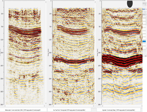
Reference Stack Final Angle Stack Angle Stacks
From the above image, we can see that the reflector at ~ 1700ms was enhanced by stacking angle stack of 20 degree angle only. Likewise, we can scan through the entire angle range and create the final stack by enhancing the reflector with the best S/N ratio using the enhancer tool.
Vertical Vrms Velocity Picking:
PSTM Imaging Selector 2Dmodule can be useful in picking the Vertical Vrms & Delta Vrms velocities. User needs to define the velocity range within the Velocity Analysis Parameters window. After defining the parameters, if user selects the automatic picking option in the Velocity Analysis parameters then the user QC the automatic picks or manually edit these automatic picks either on the Vertical semblance Delta Vrms and/or Vertical semblance Vrms vista items.
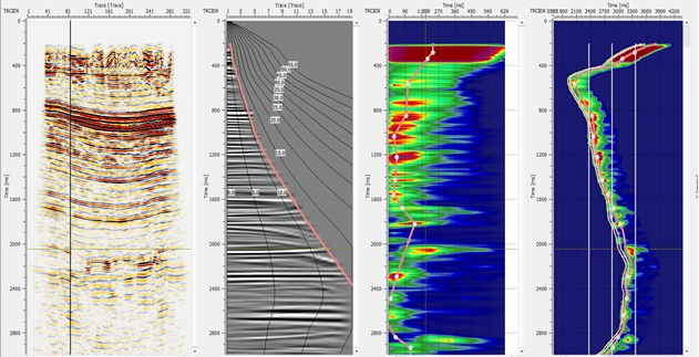
Displays of Reference stack, CIG gather at selected location on reference stack. Vertical Vrms and Delta Vrms (automatic picking)

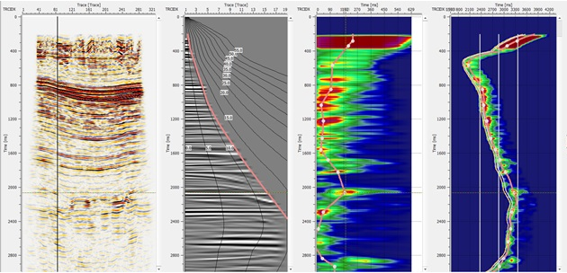
Displays of Reference stack, CIG gather at selected location on reference stack. Vertical Vrms and Delta Vrms (manual editing)
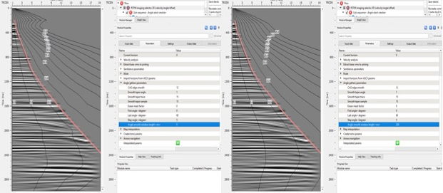
Following image(s) display the angle distribution with angle smooth window length Parameter:
User recommendation:
It is better to input the datum information prior to run the module.
Input data
Storage file
Provide Storage File in the “ Input data” tab
Parameters
Create stack by execute(can take a lot of time)
Current velocity factor
From the storage file provided in the “ Input data ” tab, all the velocity factors based on their step size are available for selection in the “ Value ” field when user selects the respective percentage velocity factor to pick angle mute.
Current angle
Inside the Angle Gathers Parameters , user have to provide the angle range to generate the Common Angle Gather (CAG) and Angle stacks. Based on the Angle step size, all the angle information is available inside the “ Value ” field. For example if an user input angle range from 0 to 60 degrees with an angle step range of 5 then it will generate the angles from 0-5, 6-10 ….56-60. Here user can select specific angle from the value field or can scroll the mouse wheel to scan through all the angles.
Current offset
From the input data tab, user provides the storage file. In the storage file, all the offset information is stored and it will be available under the Current Offset parameter inside the “ Parameter” tab. When user clicks on the “ Value ” field of the Parameters tab, it will show all the offset planes. User can select the Common Offset from this list. By default it’s Zero Offset.
HV to VV time window
HV to VV lateral window
Interpolate horizons
Datum
Provide final datum value