Geometry regularization using Virtual geometry
![]()
![]()
Regularization in 3D seismic processing reorganizes irregularly sampled field data into a uniformly spaced 3D grid (inline, crossline, and time/depth). This ensures data compatibility with processing algorithms (e.g., migration, inversion) that assume regular sampling. Midpoint consistency ensures that traces sharing the same midpoint (midway between source and receiver) are grouped and interpolated spatially and azimuthally without bias.
In this scheme, real coordinate system geometry is regularized by user defined offset and azimuth combinations virtual geometry by using either real (Cartesian) or Polar coordinate system.
![]()
![]()
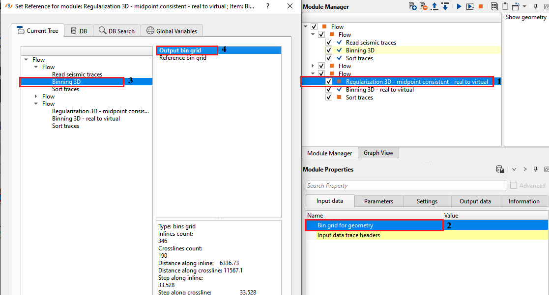
Bin grid for geometry - connect/reference to output bin grid for geometry purpose.
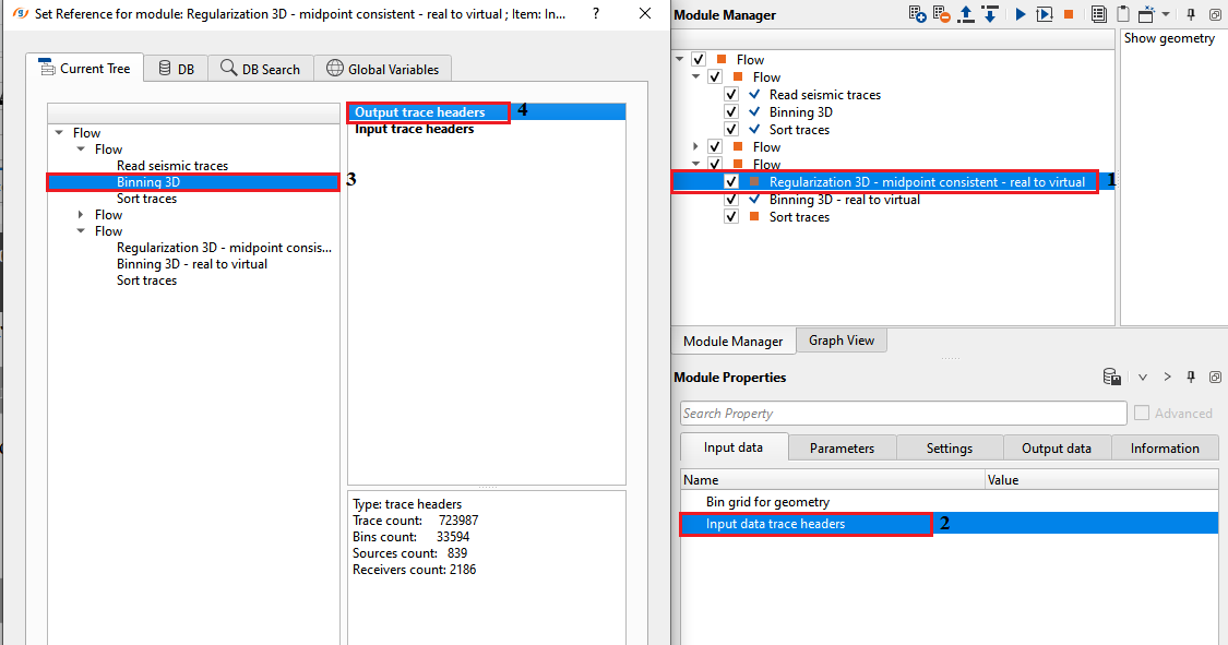
Input data trace headers - connect/reference to Output trace headers for getting the trace headers information.
![]()
![]()
Creation type { Real, Polar } - select the appropriate regularization scheme from the drop down menu. By default, Polar.
Real - it creates the regularization as per the input data or real world coordinate (Cartesian coordinate) system.
Polar - creates the regularization based on the polar coordinate systems
Midpoint aperture - specify the distance from the center of the bin to the maximum distance to look for the source-receiver combinations.
Trace aperture -
Forcibly create zero offset - by default, TRUE (Checked). It will creates the zero offsets by taking considering of the user defined Offset step.
Azimuth step - define the azimuth step to create the azimuth sectors.
Offset step - specify the offset step size.
![]()
![]()
Number of threads - One less than total no of nodes/threads to execute a job in multi-thread mode. Limit number of threads on main machine.
Skip - By default, FALSE(Unchecked). This option helps to bypass the module from the workflow.
![]()
![]()
Trace headers - generates output trace headers as a vista item.
Min fold - displays minimum fold information
Max fold - displays maximum fold information
Average fold - displays average fold information.
![]()
![]()
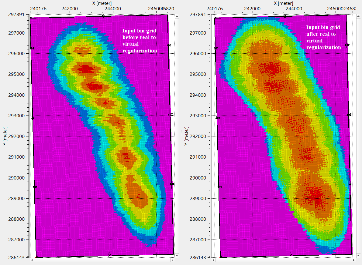
In this example workflow, regularization of the input data is carried out by using real to virtual regularization scheme.
![]()
![]()
Show geometry - click this action item to display the geometry.
![]()
![]()
YouTube video lesson, click here to open [VIDEO IN PROCESS...]
![]()
![]()
Yilmaz. O., 1987, Seismic data processing: Society of Exploration Geophysicist
 * * * If you have any questions, please send an e-mail to: support@geomage.com * * *