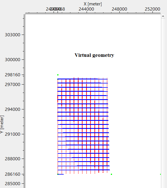
Virtual 3D geometry by common shot
![]()
![]()
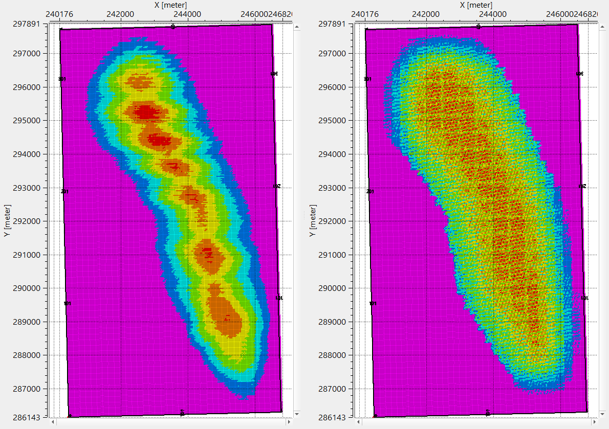
Regularization in 3D seismic processing reorganizes irregularly sampled field data into a uniformly spaced 3D grid (inline, crossline, and time/depth). This ensures data compatibility with processing algorithms (e.g., migration, inversion) that assume regular sampling. Midpoint consistency ensures that traces sharing the same midpoint (midway between source and receiver) are grouped and interpolated spatially and azimuthally without bias. T
This procedure creates regularized geometry based on common shot. For each given common shot, creates virtual regularized geometry.
![]()
![]()
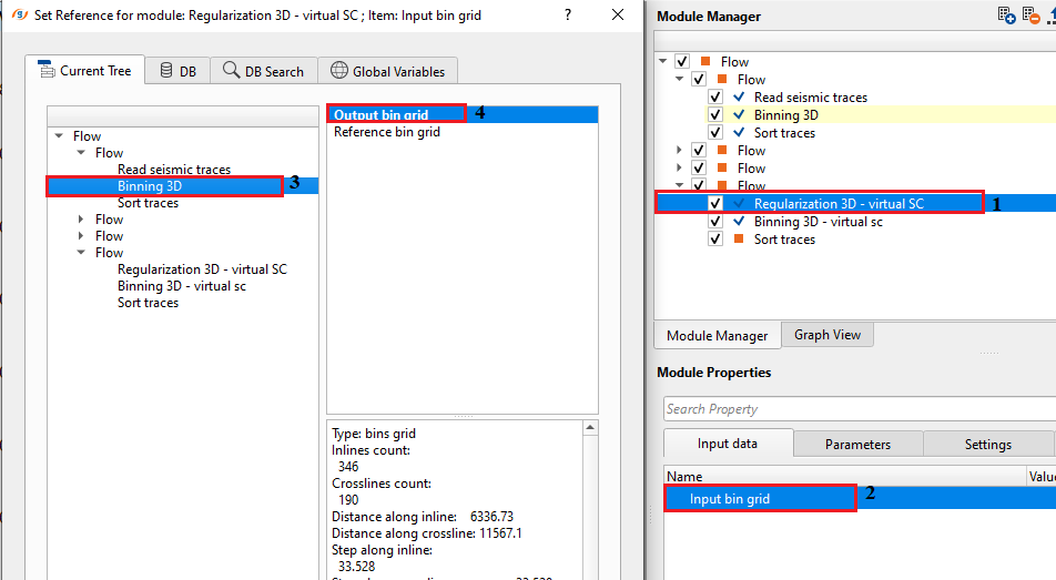
Input bin grid - connect/reference to Output bin grid. This bin grid information is used for creating regularized geometry.
![]()
![]()
Enable GUI - By default, FALSE (Unchecked).
Receiver line length - specify the receiver line length in meters.
Distance between receivers - this is the distance between two adjacent receivers. Also known as Receiver Interval.
Distance between receiver lines - specify the distance between two adjacent receiver lines.
Count of receiver lines - provide the total number of receiver lines in the survey area.
Direction of receiver line - specify the receiver line direction i.e., angle in degree of receiver lines.
1st receiver line - X coordinate of 1st receiver - specify the 1st x-coordinate of 1st receiver of the 1st receiver line
1st receiver line - Y coordinate of 1st receiver - specify the 1st y-coordinate of 1st receiver of the 1st receiver line
Source line length - specify the source line length in meters.
Distance between sources - specify the distance between two adjacent shot points. This is also known as Shot point interval.
Distance between source lines - specify the distance between two adjacent source lines.
Count of source lines - specify the total number of source lines.
Direction of source line relative to receiver line { 90, 270 } - specify the direction of shooting of shot line with respect to receiver line. By default, 90. Angle between source and receiver lines, for orthogonal acquisition system the values are 90 or 270.
1st source line - X coordinate of 1st source - specify 1st x-coordinates of 1st source of the 1st source line
1st source line - Y coordinate of 1st source - specify 1st y-coordinates of 1st source of the 1st source line
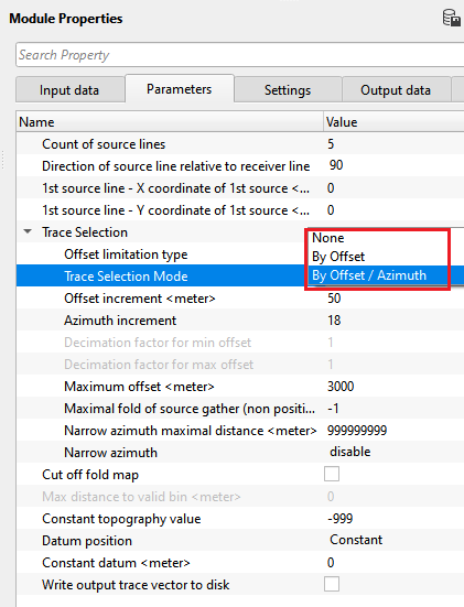
Trace Selection - this section deals with the trace selection, offset and azimuth information
Offset limitation type { Ellipse, Rectangle } - select the offset limitation by Ellipse or Rectangle. By default, Ellipse.
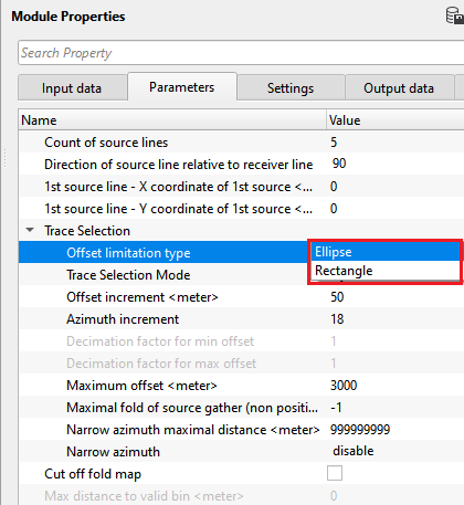
Trace Selection Mode { None, By Offset, By Offset / Azimuth } - no decimation will be used, the coverage depends on acquisition" parameters only
Trace Selection Mode - By Offset - decimation by offset with preserved azimuth distribution
Offset increment - Offset step used for decimation
Decimation factor for min offset - Decimation factor that will be used for near offset decimation
Decimation factor for max offset - Decimation factor that will be used for far offset decimation
Trace Selection Mode - By Offset / Azimuth - decimation by offset and azimuth distribution
Offset increment - see above -
Azimuth increment - Azimuth step used for decimation
Maximum offset - maximum offset for active spread
Maximal fold of source gather (non positive number: do not use) - Maximum number of traces for shot gather, decimation with preserved offset and azimuth distribution
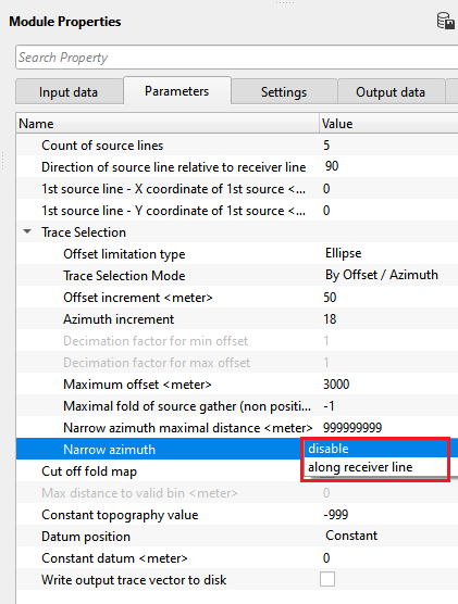
Narrow azimuth maximal distance - Maximum distance in crossline direction fro active spread
Narrow azimuth { disable, along receiver line } - Turn on / off offset limitation in crossline direction for active spread
Cut off fold map - This will produce output geometry only for bins with non zero fold according to the "Bin grid for input data"
Max distance to valid bin -
Constant topography value - Constant topography value for output geometry, -999 use values from "Bin grid for input data"
Datum position { Constant, On topography } - choose the datum position from the drop down menu. By default, On topography.
Constant datum - if datum position is Constant, specify the constant datum value.
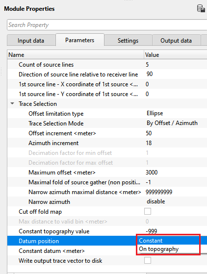
Write output trace vector to disk - this allows the user to write the output trace vector into a file
Output seismic file name - specify the output file name.
![]()
![]()
Number of threads - One less than total no of nodes/threads to execute a job in multi-thread mode. Limit number of threads on main machine.
Skip - By default, FALSE(Unchecked). This option helps to bypass the module from the workflow.
![]()
![]()
Trace headers - generates the output trace headers as a vista
Number of source gathers - displays total number of source gathers of the survey area
Minimal source fold - displays minimum source fold
Source fold - 1st quartile - displays 1st quartile source fold
Source fold - median - displays median source fold
Source fold - 3rd quartile - displays 3rd quartile source fold
Maximal source fold - displays maximum source fold
![]()
![]()
In this example workflow, the user has to define the survey geometry parameters like source and receiver intervals, source and receiver lines, offsets and coordinates etc in the parameters field.
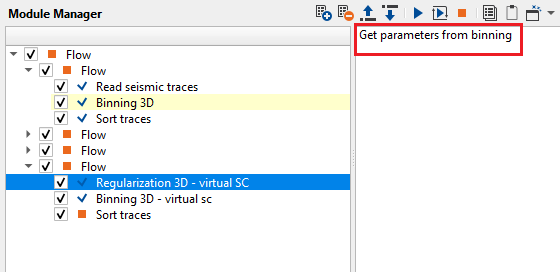
In case the user wants to use the parameters of the input data, click on the action items option "Get parameters from binning". It will automatically fills the parameters however the user MUST pay attention to the automatically filled parameters. It is the user's responsibility to input the correct parameters for creating a virtual surface consistent regularization scheme.
![]()
![]()
Get parameters from binning - this allows the user to get all the parameters required for binning. Click this option and it will automatically fills the parameters information from the trace headers.
![]()
![]()
YouTube video lesson, click here to open [VIDEO IN PROCESS...]
![]()
![]()
Yilmaz. O., 1987, Seismic data processing: Society of Exploration Geophysicist
 * * * If you have any questions, please send an e-mail to: support@geomage.com * * *