Attenuation of coherent noise (ground roll) in radial domain
![]()
![]()
The radial trace transform is a simple transform to map gathers in t-x domain into an apparent velocity and travel time domain. In radial domain, traces are reorganized based on their angle/apparent velocity rather than the conventional source-receiver offset coordinates.
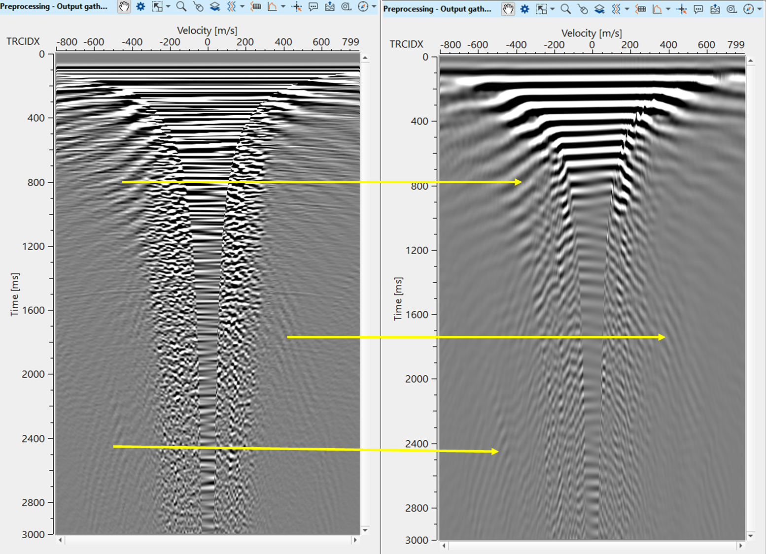
Noise like ground roll and diffractions exhibit strong coherent patterns in the radial domain compared to the time-offset domain. It makes it easier to attenuate in the radial domain than in t-x domain. Ground roll contaminates the near offset traces in the t-x domain with low frequency & high amplitudes. When the ground roll is transformed in to radial domain, it forms a linear or fan like pattern and it is easily distinguishable with hyperbolic reflections/events.
The apparent frequency of the ground roll will also be transformed in the RT domain. Ground roll can be extracted via the use of filters in the RT domain, to generate a noise model. This noise model can then be adaptively subtracted from the original input data. Results show that this method produces better results than an F-K filter, with less reduction in the amplitude spectrum.
The radial transform is defined by:
Where
x - offset (distance between source and receiver)
t - two way travel time
v - apparent velocity
![]()
![]()
Input DataItem
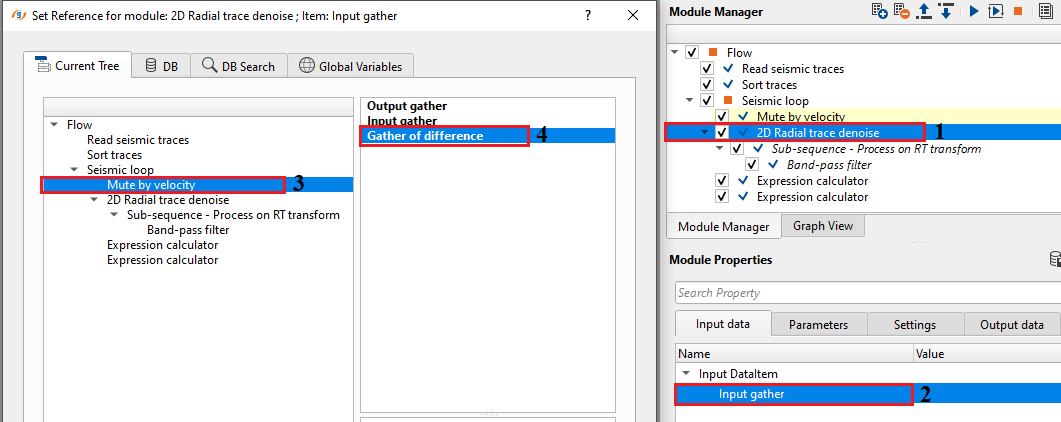
Input gather - connect/reference to input gather that should be transformed to radial domain. Usually shot gather or cmp gather with increasing offset is an ideal as input gather.
![]()
![]()
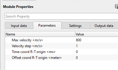
Max velocity - specify the maximum velocity that should be considered in the radial trace domain to align the seismic traces along the radial domain.
Velocity step - a smaller velocity step improves the noise attenuation however increases the computation time. Specify the velocity step size that is used as an interval in the radial trace domain. This determines the resolution of gather in radial(R-T) domain.
Time coord R-T origin - specify the starting time. This value ensures that both seismic wavelet initiation time and radial trace initiation time aligns to better separate the signal and noise based on the coherency of the noise. By default, 0 which should be good.
Offset coord R-T origin - it helps in modeling of the linear (ground roll) and hyperbolic events based on the spatial variation of the seismic data. Ground roll concentrates in the near offset area. By default, 0 and keep the value same.
![]()
![]()
Auto-connection - By default, TRUE(Checked).It will automatically connects to the next module. To avoid auto-connect, the user should uncheck this option.
Bad data values option { Fix, Notify, Continue } - This is applicable whenever there is a bad value or NaN (Not a Number) in the data. By default, Notify. While testing, it is good to opt as Notify option. Once we understand the root cause of it, the user can either choose the option Fix or Continue. In this way, the job won't stop/fail during the production.
Notify - It will notify the issue if there are any bad values or NaN. This is halt the workflow execution.
Fix - It will fix the bad values and continue executing the workflow.
Continue - This option will continue the execution of the workflow however if there are any bad values or NaN, it won't fix it.
Calculate difference - This option creates the difference display gather between input and output gathers. By default Unchecked. To create a difference, check the option.
Number of threads - One less than total no of nodes/threads to execute a job in multi-thread mode. Limit number of threads on main machine.
Skip - By default, FALSE(Unchecked). This option helps to bypass the module from the workflow.
![]()
![]()
Output DataItem
Output gather - generates the radial trace denoise output gather. This can be used as an connection/reference to the next module.
Gather of difference - generates the difference between the input and output gather.
Output gather - generates the R-T transformed output gather as processing output gather.
There is no information available for this module so the user can ignore it.
![]()
![]()
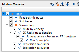
In this example, we use radial trace denoise module along with band pass as a sub-sequence procedure. The idea behind applying a band pass filter inside the radial trace denoise module is to filter out the low frequency ground roll noise in the radial domain. It is easier to distinguish the linear and hyperbolic events in R-T or radial trace domain.
We provide an input along with ground roll to the radial trace domain module however this input majorly consists of the ground roll and bit of primary energy. For this application, we are using Mute by velocity module to prepare the input data for Radial trace denoise module. We consider the difference gather as an input to Radial trace denoise module.
Execute the module 2D radial trace denoise module after setting up the parameters. Launch Vista items. It generates, Input, Output, Difference and Processing Output gather.
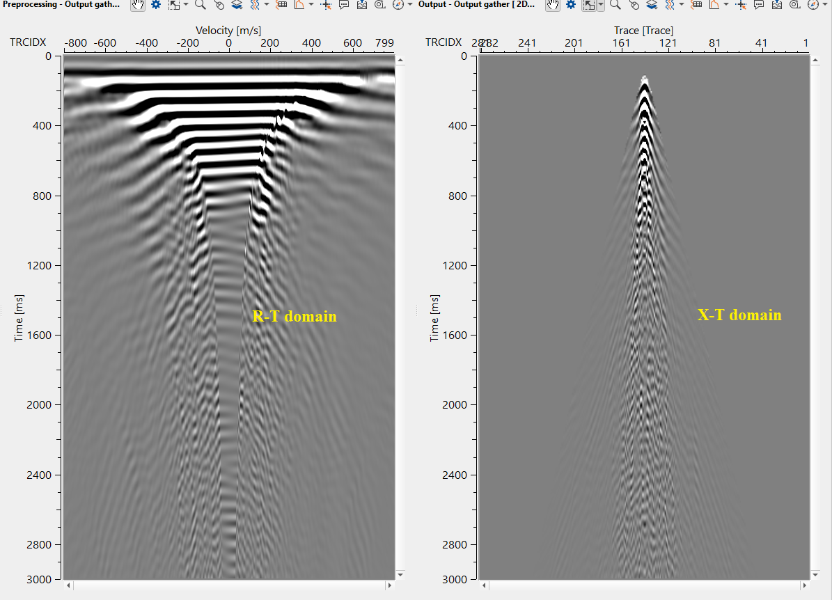
Let's look into Processing - Output gather. This is the output in radial trace (R-T) domain after transformation. We can clearly distinguish between the hyperbolic and linear events in the R-T domain as shown in the below figure.
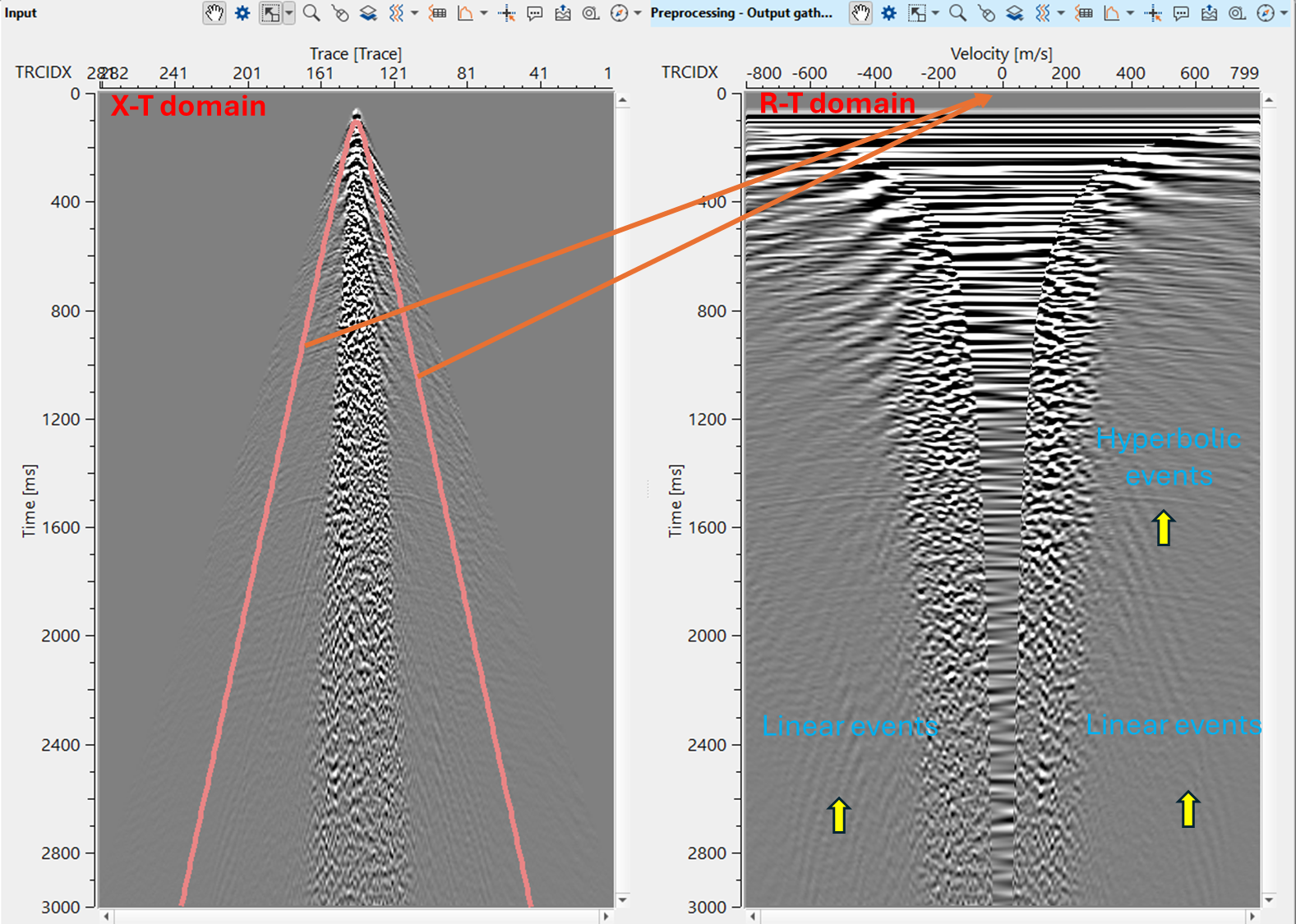
When the data transformed from X-T domain to R-T domain, each trace is aligned along the radial domain with a velocity ranging from 0 to 800 m/s with a velocity step size of 1 m/s. On the horizontal axis, we observe all the ground roll velocities starting from ~400 m/s to 800 m/s in the form of linear events. With the combination of band pass filter, we attenuate these low frequency ground roll in the R-T domain and later transform them back to X-T domain.
After transformed back from R-T domain to T-X domain, final output gather looks as shown below
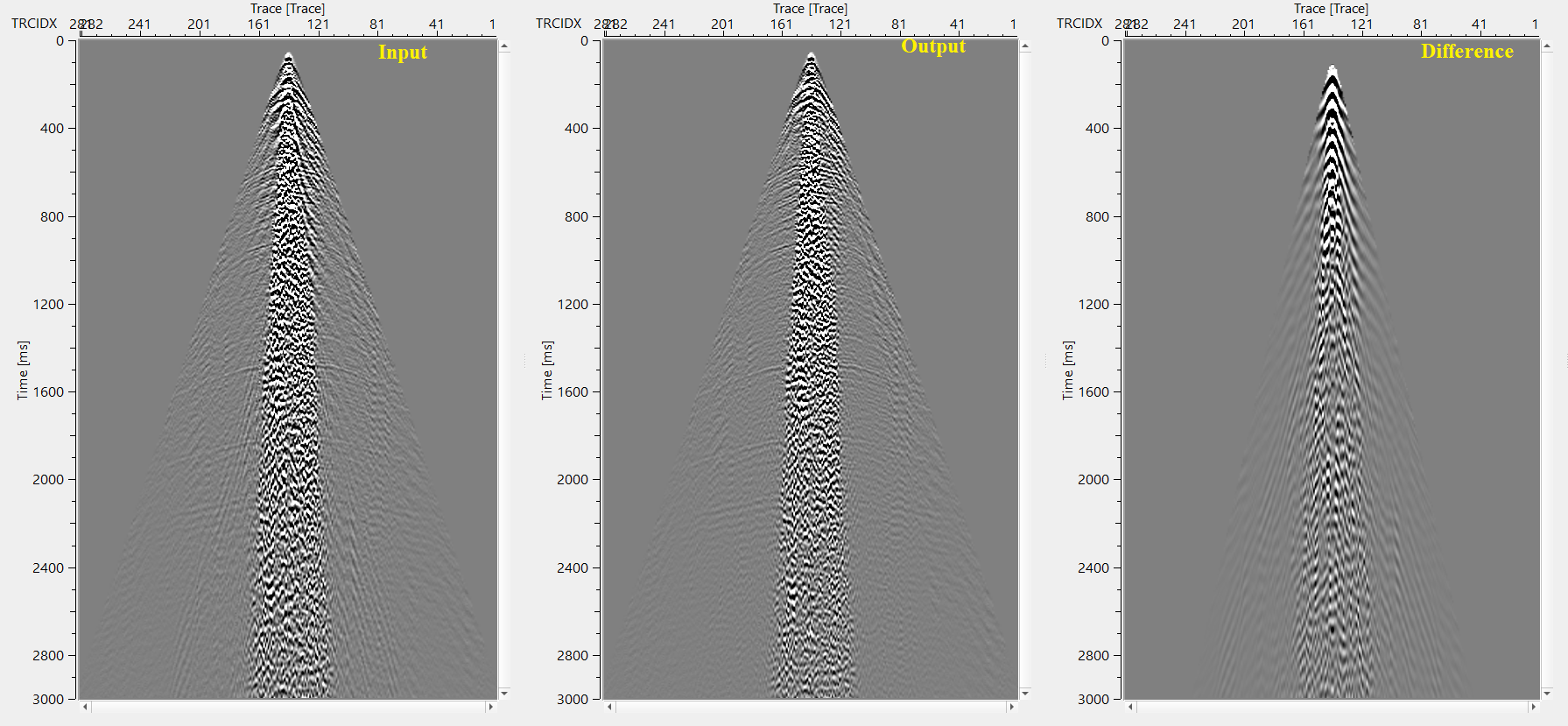
Final output of the full gather should be shown in the below image after applying expression calculator procedure.
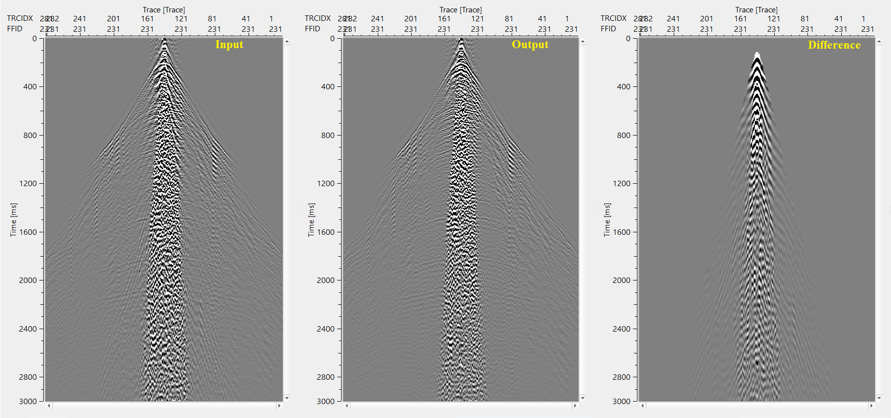
Expression calculator - In the 1st expression calculator, Output gather of Mute by velocity is connected/referenced as Gather A and Difference gather of 2D radial trace denoise as Gather B. In the expression, we added (A+B) these two gathers to get an output. 2nd Expression calculator is used to generate the difference for QC purpose. Input of Mute by velocity is connected/referenced as Gather A and Output from Expression calculator is connected/referenced as Gather B. In the expression field, subtract (A-B) one from the other to generate the difference gather.
![]()
![]()
There are no action items available for this module so the user can ignore it.
![]()
![]()
YouTube video lesson, click here to open [VIDEO IN PROCESS...]
![]()
![]()
Yilmaz. O., 1987, Seismic data processing: Society of Exploration Geophysicist
 * * * If you have any questions, please send an e-mail to: support@geomage.com * * *