Geometry regularization using Spiral coordinate system
![]()
![]()
Regularization in 3D seismic processing reorganizes irregularly sampled field data into a uniformly spaced 3D grid (inline, crossline, and time/depth). This ensures data compatibility with processing algorithms (e.g., migration, inversion) that assume regular sampling. Midpoint consistency ensures that traces sharing the same midpoint (midway between source and receiver) are grouped and interpolated spatially and azimuthally without bias.
![]()
![]()
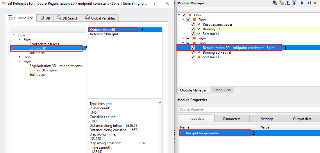
Bin grid for geometry - connect/reference to the Output bin grid.
![]()
![]()
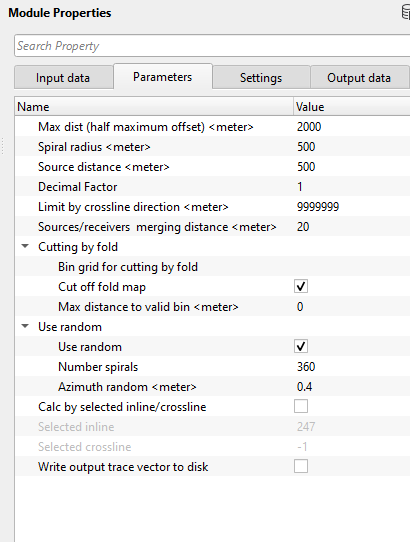
Max dist (half maximum offset) - specify the maximum distance to be considered in the spiral geometry calculation.
Spiral radius - specify the spiral radius from the center of the mid point.
Source distance - specify the source distance between adjacent sources.
Decimal Factor - this parameter decimates the total number of sources and receivers. By default, 1.
Limit by crossline direction - specify the maximum distance along the crossline direction. Keep the default value and no need to change it.
Sources/receivers merging distance - there are many source-receiver combinations associated for each bin. For a selected bin, the source-receiver combination may have many sources and receivers. We assign the same coordinates of a source (associated with the selected bin) for remaining sources falling within user defined source merging distance. Similarly, assign the same receiver (associated with the selected bin) coordinates for the receivers falling within the user defined receiver merging distance.
Cutting by fold - this section takes care of the geometry where the fold is zero or emtpy.
Bin grid for cutting by fold - connect/reference to the output bin grid for not calculating regularization for the empty fold bins.
Cut off fold map - By default, TRUE (Checked). It will not consider the bins with Zero fold.
Max distance to valid bin - specify the maximum distance to valid bin. This value is important in finding the zero fold bins. If there are any bins falling within the user defined distance with zero fold it will not consider any bins in the regularization process.
Use random - this section deals with the spiral randomization.
Use random - By default, TRUE (Checked). It uses spiral randomization during the regularization process.
Number spirals - By default, 360.
Azimuth random -
Calc by selected inline/crossline - it calculates the regularization for a selected inline/crossline.
Selected inline - specify the inline number to do the spiral regularization.
Selected crossline - specify the crossline number to perform the spiral regularization
Write output trace vector to disk - this option allows the user to output the trace vector. This output file saved with an extension of ".gsdl"
Output seismic file name - specify the output file name of the selected inline/crossline after spiral regularization.
![]()
![]()
Number of threads - One less than total no of nodes/threads to execute a job in multi-thread mode. Limit number of threads on main machine.
Skip - By default, FALSE(Unchecked). This option helps to bypass the module from the workflow.
![]()
![]()
Trace headers - generates the regularized (spiral) output traces as a vista item.
Nominal traces count - displays total number of nominal traces for selected bin (as per user defined spiral parameters). It changes the value if the selected bin is somewhere near the edge of the survey.
![]()
![]()
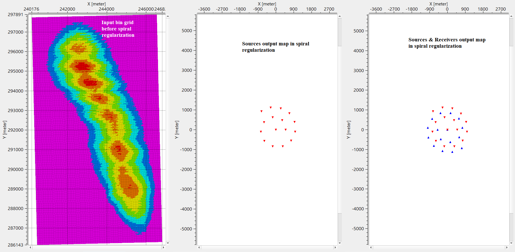
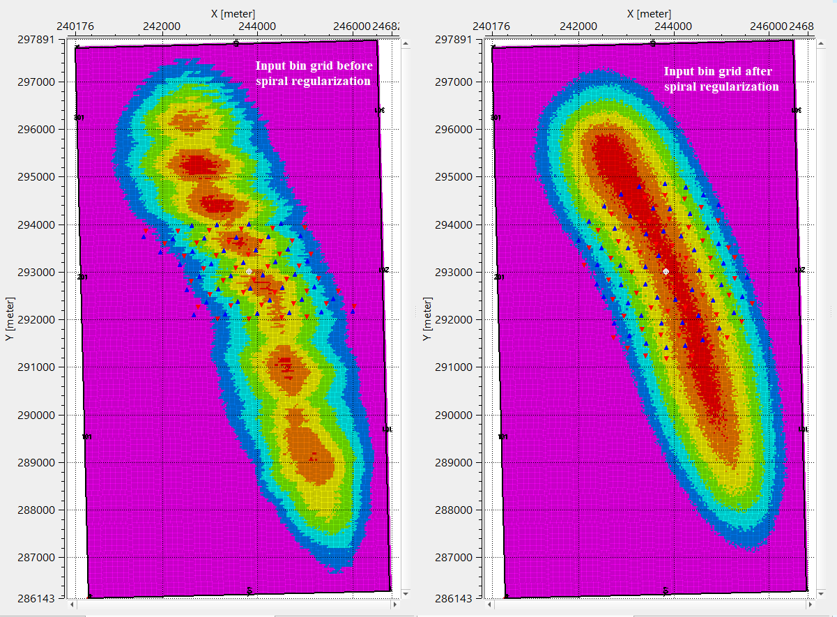
In this example workflow, regularize the input data by using Spiral coordinate system.
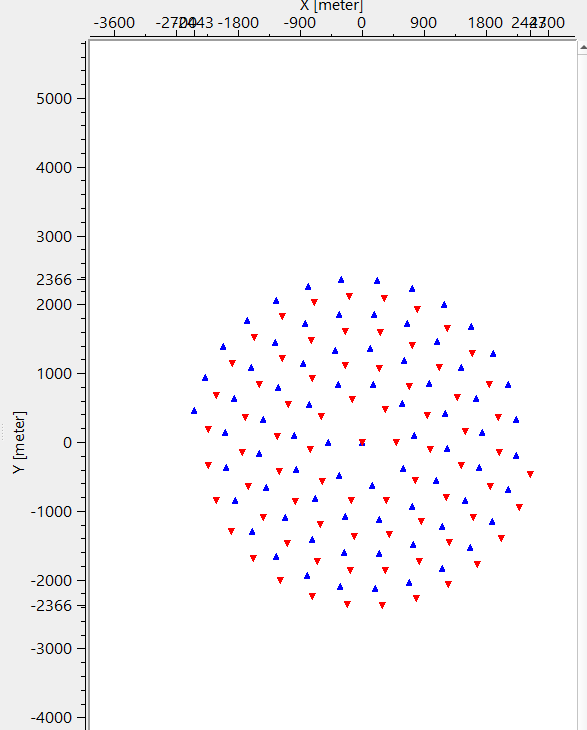
Assign the parameters as per the input data requirement and execute the module. This module generates Location map & Output map. To generate the Output map, the user should click on "Show geometry" option in the Action items menu. It will show the Spiral geometry of Sources & Receivers in the Output map.
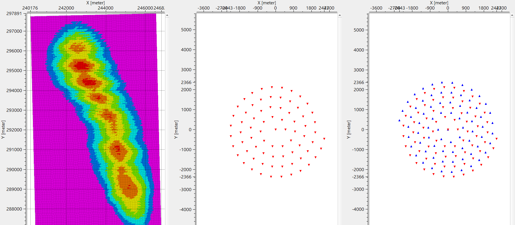
After the regularization, compare the results before and after Spiral regularization by binning the output trace headers from Regularization 3D - mind point consistent - Spiral module. Look at the location maps before and after spiral regularization.
![]()
![]()
Show geometry - this option allows the user to generate/display the output spiral geometry of sources and receivers of the selected bin. 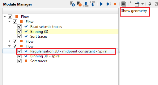
![]()
![]()
YouTube video lesson, click here to open [VIDEO IN PROCESS...]
![]()
![]()
Yilmaz. O., 1987, Seismic data processing: Society of Exploration Geophysicist
 * * * If you have any questions, please send an e-mail to: support@geomage.com * * *