Virtual 3D geometry by common offsets
![]()
![]()
Regularization in 3D seismic processing reorganizes irregularly sampled field data into a uniformly spaced 3D grid (inline, crossline, and time/depth). This ensures data compatibility with processing algorithms (e.g., migration, inversion) that assume regular sampling. Midpoint consistency ensures that traces sharing the same midpoint (midway between source and receiver) are grouped and interpolated spatially and azimuthally without bias.
This procedure creates regularized geometry based on midpoint. For each given midpoint, virtual geometry with regularized offsets will be created. In this method, the data is transformed from Cartesian coordinate system to Polar coordinate system. In the polar coordinate system, it considers the radii(r , distance from the center point or CMP), azimuth (θ) and vertical distance (z). This regularization method is useful for circular geometry like borehole VSP, Ocean Bottom Node (OBN) and land seismic surveys with radial geometry set up.
In this method, the user provides the minimum & maximum offsets to be considered for the regularized geometry with an offset step size. Similarly, azimuths should be mentioned and they are divided into different azimuth sectors with a step size.
![]()
![]()
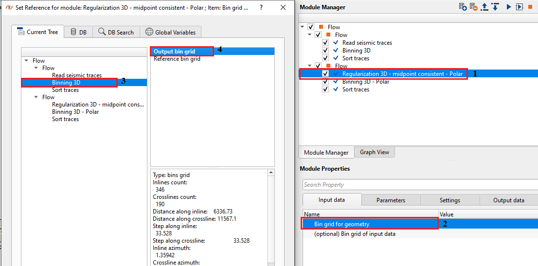
Bin grid for geometry - connect/reference to Output bin grid. This bin grid is used for the geometry
(optional) Bin grid of input data - this is optional however if the user wants to assign a different bin grid connect to the output bin grid.
![]()
![]()
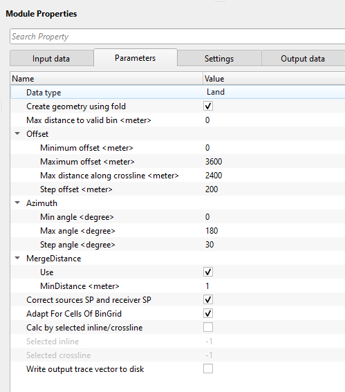
Data type { Land, Marine } - choose the input data type from the drop down menu. By default, Land.
Create geometry using fold - This will produce output geometry only for bins with non zero fold according to the "Bin grid for input data"
Max distance to valid bin -
Offset - Offset parameters for output geometry
Minimum offset - Minimum offset value to be calculated
Maximum offset - Maximum offset value to be calculated
Max distance along crossline - Maximum offset in crossline direction
Step offset - Offset step used for geometry calculation
Azimuth - Azimuth parameters for output geometry. Azimuths are divided into different azimuth sectors starting from 0 to 180 with a user defined step size.
Min angle - Minimum angle (from inline direction) value to be calculated
Max angle - Maximum angle (from inline direction) value to be calculated
Step angle - Angle step used for geometry calculation
MergeDistance - Merging of created source/receivers decrease the number of unique sources and receivers
Use - By default, TRUE (Checked).
MinDistance - Maximum distance between sources/receivers that will be merged
Correct sources SP and receiver SP - For the created sources and receivers will be assigned source/receiver station number according to the following expression:
Rec station = 10000*Inline number + Crossline number
Source station = 10000*Crossline number + Inline number
merging of created source/receivers decrease the number of unique sources and receivers.
Adapt For Cells Of BinGrid - The coordinates of the created sources and receivers will be set to center of the nearest bin
Calc by selected inline/crossline - this option allows the user to calculate the geometry by selected inline or crossline.
Selected inline - specify an inline number to do the geometry calculation. By default, -1 which means all inlines will be calculated.
Selected crossline - specify a crossline number to do the geometry calculation. By default, -1 which means all crosslines will be calculated.
Write output trace vector to disk - By default, FALSE (Unchecked). This will output the trace vector as .gsdl file
Output seismic file name - specify the output file name.
![]()
![]()
Number of threads - One less than total no of nodes/threads to execute a job in multi-thread mode. Limit number of threads on main machine.
Skip - By default, FALSE(Unchecked). This option helps to bypass the module from the workflow.
![]()
![]()
Trace headers geometry - generates the regularized output trace headers geometry for further use.
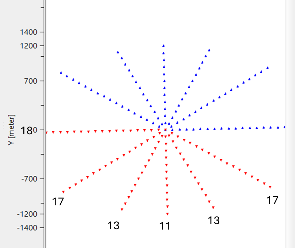
Nominal traces count - total number of nominal traces. Based on the user provided inline, crossline offsets and offset step size, it generates the nominal trace count. For example, minimum(0) and maximum(3600) offsets are defined with a offset step size of 200m & maximum distance along Crossline as 2400 and azimuth sectors from 0 to 180 with an azimuth step of 30 gives 6 sectors. For maximum offset it creates 18 sources , 17 (twice) sources, 13 (twice) sources and 11 sources (maximum distance along crossline) so in total ((18+17+13+11+13+17)+1 = 90).
![]()
![]()
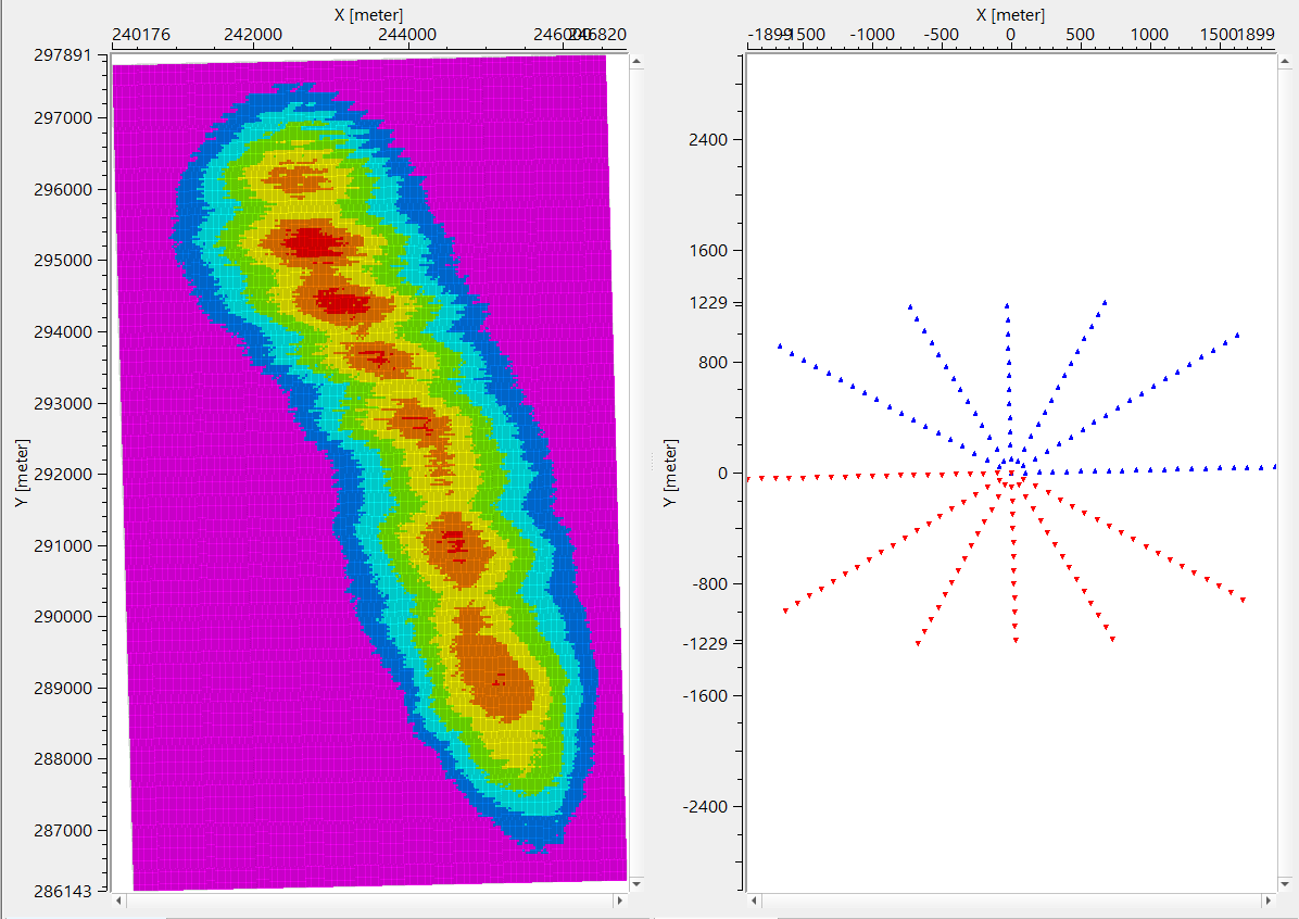
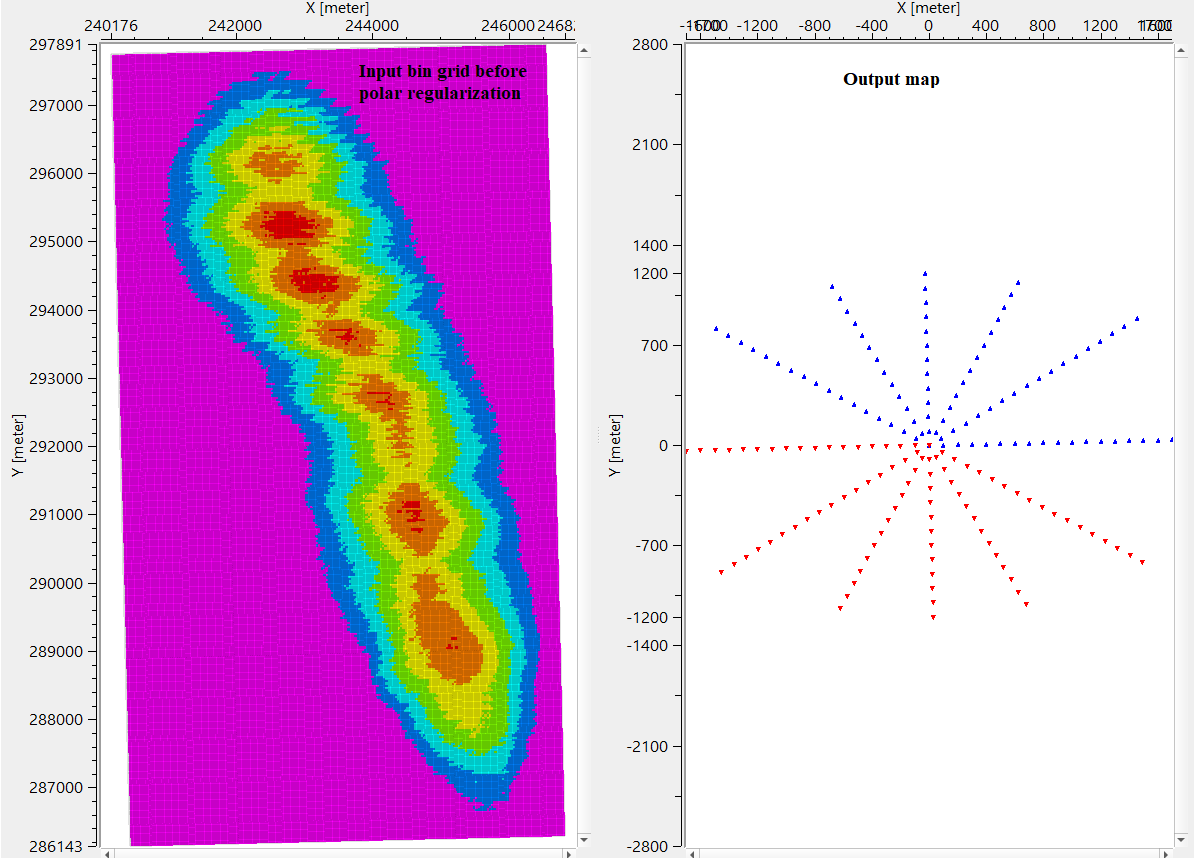
In this example workflow, we regularized the geometry using Polar regularization method.
Provide required parameters and execute the module. It generates the location map along with the Output map of regularized offset distribution.
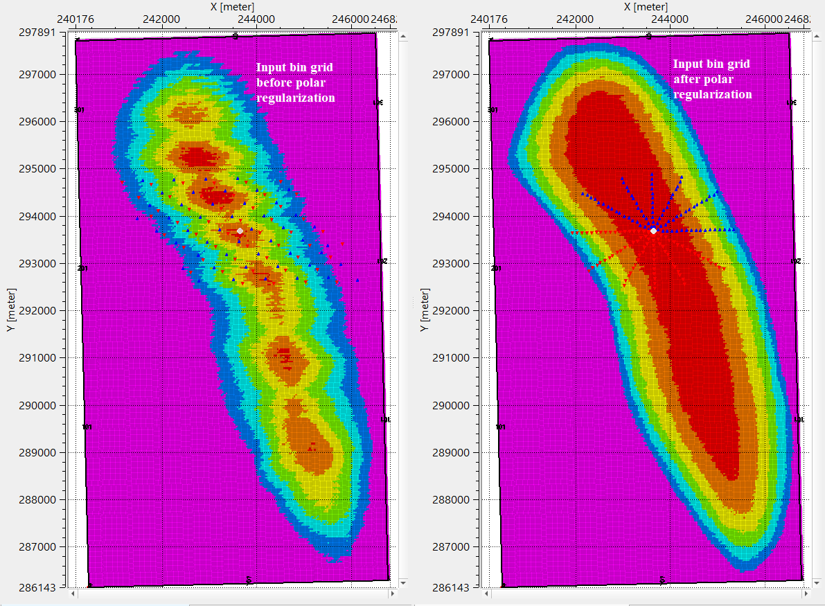
After the regularization, take the output trace headers from Regularization 3D - mid point consistent - Polar module and do binning using Binning 3D module. Compare the location maps of both.
![]()
![]()
There are no action items available for this module so the user can ignore it.
![]()
![]()
YouTube video lesson, click here to open [VIDEO IN PROCESS...]
![]()
![]()
Yilmaz. O., 1987, Seismic data processing: Society of Exploration Geophysicist
 * * * If you have any questions, please send an e-mail to: support@geomage.com * * *