Polarization detection
Finding the direction and wave pattern of the seismic data
Theory
What is Polarization Detection?
Polarization detection (or polarization analysis) is a method used to determine the direction and type of particle motion of seismic waves recorded at a receiver.
In simple terms:
Polarization tells you how the ground is moving — in which direction and with what pattern — when a seismic wave arrives.
It is mainly used in:
- Microseismic monitoring
- Earthquake seismology
- VSP (Vertical Seismic Profiling)
- Multicomponent (3-C / 3-D) seismic surveys
- Fracture and anisotropy analysis
- Noise suppression using directional filters
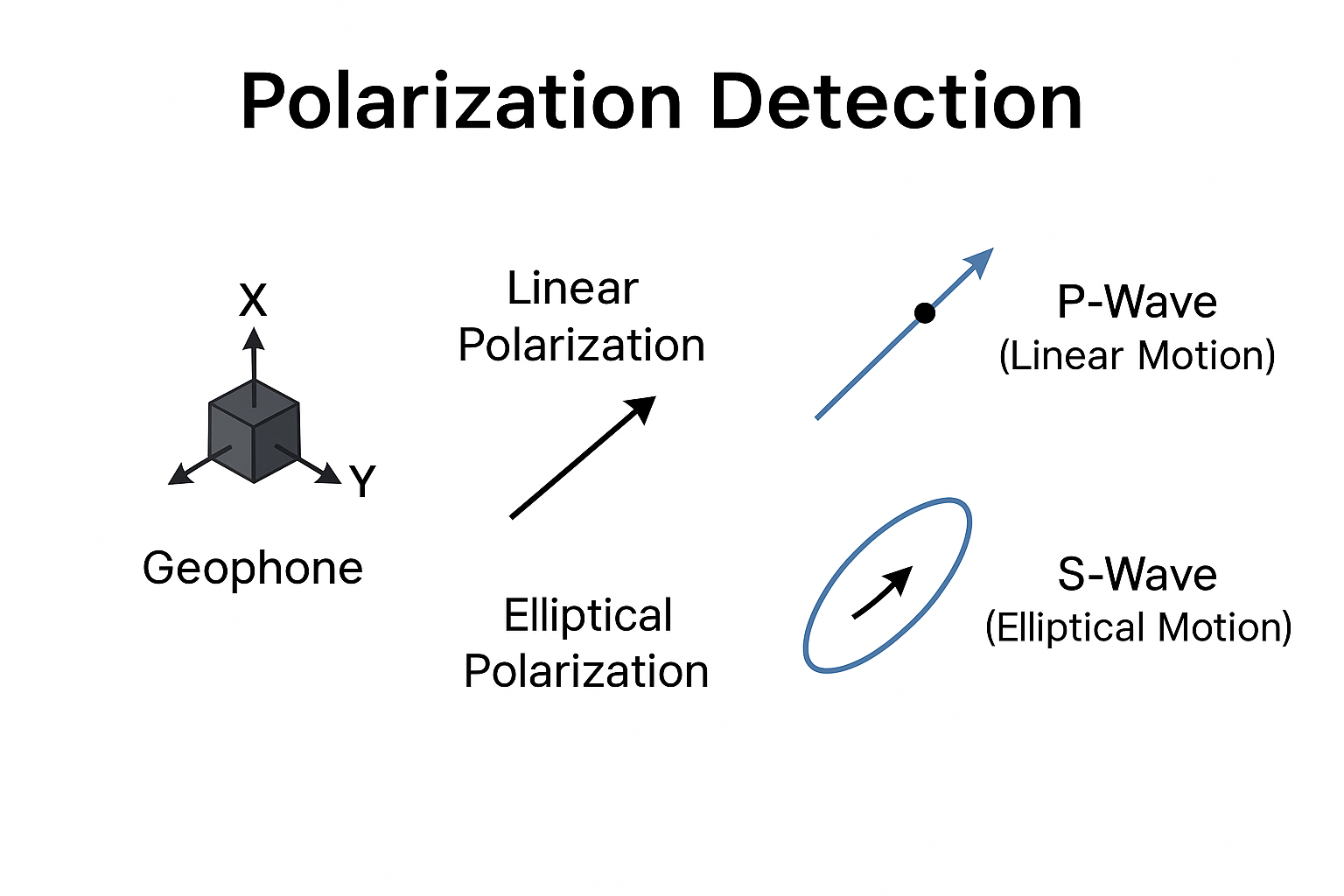
Polarization helps identify:
- P-wave arrivals (mostly linear motion)
- S-wave arrivals (often elliptical or linear depending on mode)
- Surface waves (often elliptical or retrograde motion)
- Noise direction (wind noise, traffic noise)
- Wave propagation direction to the receiver
How Polarization Detection Works ?
A receiver records particle motion in three components:
- X = East–West
- Y = North–South
- Z = Vertical
Polarization algorithms analyze the covariance of these components over a short time window.
Typical results include:
- Azimuth (direction of incoming wave)
- Dip (vertical angle of arrival)
- Linearity (is motion straight-line or curved?)
- Ellipticity (shape of particle motion ellipse)
- P vs S wave identification
Example:
- Linear motion → likely P-wave
- Horizontal elliptical motion → S-wave
- Retrograde elliptical → Rayleigh wave
Why is Polarization Detection Used?
- Identify wave types (P, S, surface waves)
- Detect direction of arrival (azimuth + dip)
- Suppress noise using directional filters
- Improve first-break picking
- Locate microseismic events
- Analyze rock anisotropy / fractures
It is very useful when processing multicomponent seismic or VSP data.
Input Data Requirements for Polarization Detection
Polarization detection requires vector data, not scalar data.
1. Three-Component Data (Mandatory)
You need 3-component geophones:
- Vertical (Z)
- Horizontal 1 (X)
- Horizontal 2 (Y)
Single-component (vertical-only) seismic cannot be polarized.
2. Synchronized Components
All 3 components must have:
- Same time sampling
- Same number of samples
- Same instrument response
3. Properly Oriented Sensors
Sensor axes must be:
- Calibrated
- Correctly oriented (true North, East, vertical)
- Corrected for tilt if necessary
4. Clean, high SNR data
Polarization works best when:
- There is a clear wave arrival
- Noise is not overwhelming
5. Window Length Selection
A proper time window must be chosen (e.g., 20–60 ms) around each event.
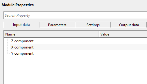
Input data
Z component
connect/reference to Z component data
X component
connect/reference to X component data
Y component
connect/reference to Y component data
Parameters
Vertical window
it is used to calculate the multi component data attributes like azimuth, angle, ellipticity etc.,. Provide the vertical window size in milliseconds.
Settings
Skip
By default, FALSE(Unchecked). This option helps to bypass the module from the workflow.
Output data
Angle gather
generates the angle gathers which measures the horizontal directions of the seismic wave arrivals
Azimuth gather
generates the azimuth gathers which measures the vertical directions of the seismic wave arrivals
Output gather
generates the output gathers
Information
There is no information available for this module.
Examples
Actions
There are no action items available for this module so the user can ignore it.
Video lesson
YouTube video lesson, click here to open [VIDEO IN PROCESS...]
Related articles
Yilmaz. O., 1987, Seismic data processing: Society of Exploration Geophysicist
 * * * If you have any questions, please send an e-mail to: support@geomage.com * * *
