Creates Depth velocity model by using BMP image
![]()
![]()
This procedure converts Grey scale ".BMP" image into the velocity depth model.
Input data – Grey scale BMP image
Output data – Velocity depth gather
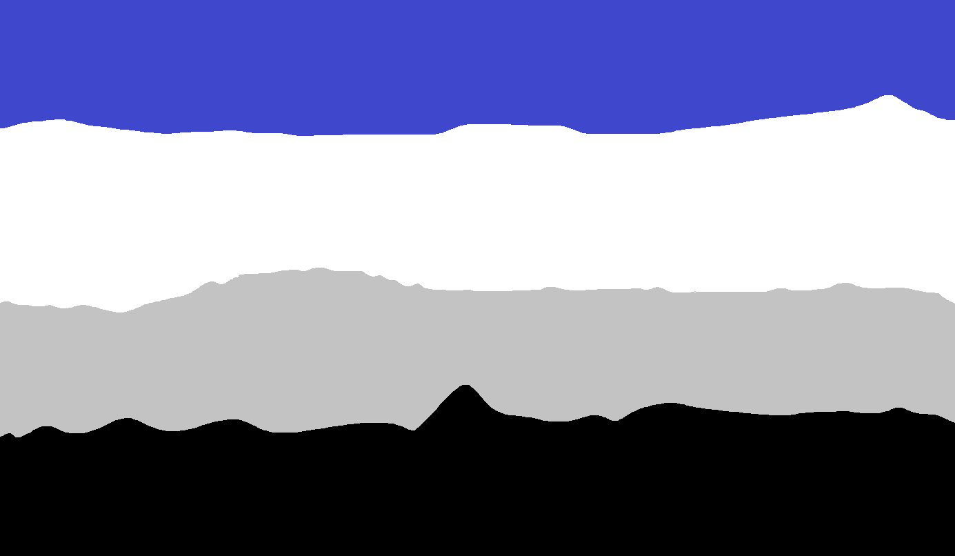
Visual – Velocity depth model
![]()
![]()
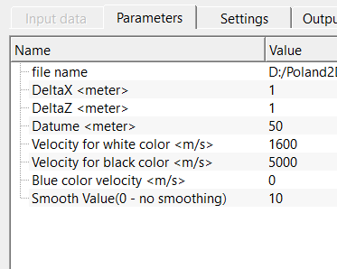
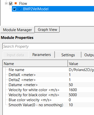
Input file should be provided in the Parameters tab.
![]()
![]()
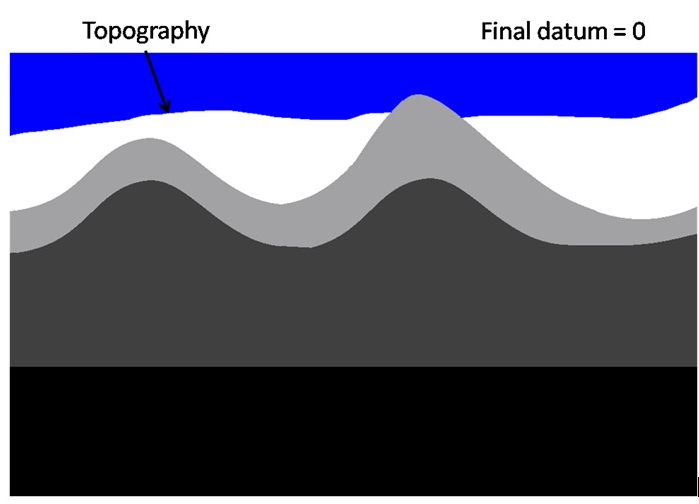
file name - provide 256 color Grey scale ".BMP" image file. In order to produce the model from final datum, the layer above surface must be filled with blue (RGB: 0:0:255) color
Specify the full path to the input BMP image file. The image must be a greyscale BMP (each pixel described by equal red, green, and blue channel values from 0 to 255). The width of the image (number of pixel columns) determines the number of output traces (CDPs), and the height (number of pixel rows) determines the number of depth samples per trace. If any region of the image above the topographic surface needs to be treated as an above-datum zone, paint those pixels pure blue (RGB 0:0:255) before using the file. Non-grey, non-blue pixels are automatically converted to grey by using the red channel value, so artefacts from colour conversion are possible — prepare the image as a true greyscale BMP for best results.
DeltaX - horizontal size of one pixel of the image. By default, 1
The lateral (horizontal) distance in metres that each pixel column represents in the real earth model. This value controls the x-coordinates assigned to output traces: trace i is placed at x = i * DeltaX metres. Set this to match the spatial scale of your model — for example, if the image is 500 pixels wide and the model covers 5000 m, set DeltaX to 10. Default: 1 m.
DeltaZ - vertical size of one pixel of the image. By default, 1.
The vertical (depth) distance in metres that each pixel row represents in the real earth model. This value sets the depth sampling interval of the output velocity gather. For example, if the image has 300 rows and the model must span 3000 m of depth, set DeltaZ to 10. Accurate calibration of DeltaZ is critical: an incorrect value will stretch or compress the entire depth axis of the resulting velocity model. Default: 1 m.
Datum - provide the datum value. By default, 1000 m/sec.
The elevation of the processing datum in metres above sea level (or above any consistent vertical reference). This value is stored in the output trace headers and is used to calculate the actual surface elevation at each trace location: the elevation below the datum is computed as Datum minus the depth of the topography boundary detected from the blue region. If your data was processed with a flat datum of 500 m, enter 500 here. Note that the unit label in the interface may show "m/sec" but the parameter is a depth/elevation value in metres. Default: 1000 m.
Velocity for white color - velocity that corresponds to the white color of the image. Default, 1600 m/sec.
The seismic velocity in m/s assigned to pure white pixels (brightness = 255) in the BMP image. White typically represents slow, near-surface or shallow formations such as unconsolidated sediments or water. Together with the Velocity for black color, this value defines the two endpoints of the linear velocity-to-brightness mapping. All intermediate grey shades receive proportionally interpolated velocities. Set this to the minimum expected velocity in your model. Default: 1600 m/s (approximately the velocity of water).
Velocity for black color - velocity that corresponds to the black color of the image. The velocities corresponding to the colors differs from white/black will be interpolated. By default, 5000 m/sec.
The seismic velocity in m/s assigned to pure black pixels (brightness = 0) in the BMP image. Black typically represents fast, deep, consolidated formations such as carbonates or basement rocks. The velocity mapping formula is: V = VelocityWhite + (255 - brightness) / 255 * (VelocityBlack - VelocityWhite). Set this to the maximum expected interval velocity in your model. Default: 5000 m/s.
Blue color velocity - velocity that corresponds to the blue (RGB 0:0:255) color of the image. This velocity will be used to fill model above the topography level, the topography will be determined as top of the layer below blue. The elevation below the final datum equals to zero will be written in to the output SEG-Y trace header as positive number. By default, 0 m/sec.
The velocity in m/s assigned to all pixels identified as pure blue (RGB 0:0:255) in the BMP image. The blue region represents the zone above the topographic surface or the above-datum replacement layer. Setting this to 0 m/s flags those samples as invalid or above-surface. Alternatively, set it to the replacement velocity (e.g., 1500 m/s for a water-replacement datum) so that the output model is fully populated and ready for use in depth migration. The bottom of the continuous blue region in each column is detected and used to extract the topography line, which is then smoothed and stored in the trace headers. Default: 0 m/s.
Smooth Value(0 - no smoothing) - specify whether smoothing should be applied to the output velocity model or not. By default, 10. If this value is Zero (0) which means no smoothing of output velocity gather.
Controls the amount of lateral smoothing applied to the detected topography line (the boundary between the blue above-surface region and the velocity model below). This parameter does not smooth the velocity field itself — it smooths the topography curve that is stored in the output trace headers. A value of 0 disables smoothing entirely and the raw pixel-by-pixel topography is used. Larger values produce a progressively smoother topography curve, which is useful when the blue boundary in the image has a ragged or pixelated edge that should represent a geologically smooth surface. Use low values (1–5) to preserve sharp topographic features, and higher values (10–30) for regional-scale smooth surfaces. Default: 10.
![]()
![]()
Skip - By default, FALSE(Unchecked). This option helps to bypass the module from the workflow.
When checked, the module is bypassed and performs no processing. This allows you to temporarily disable the BMP2VelModel step in a workflow without removing or reconfiguring it. Default: unchecked (module is active).
![]()
![]()
Gather - OUT - outputs velocity gather as an output gather.
The output depth-domain interval velocity gather derived from the BMP image. Each trace in the gather corresponds to one pixel column of the input image, and each sample represents the interval velocity at a specific depth, sampled at the DeltaZ interval. Trace x-coordinates are spaced at DeltaX intervals, and the topography elevation derived from the blue region is stored in the trace headers. This gather can be visualised as a 2D velocity-depth model, connected to the Translate velocities module for format conversion, or passed to a depth migration module as the velocity field.
BMP2VelModel converts a greyscale BMP image into a depth-domain interval velocity model that can be used directly in migration, model building, and depth-to-time conversion workflows. Each column of pixels in the image becomes one vertical velocity profile (one trace in the output gather), and each row of pixels becomes one depth sample. Pixel brightness is mapped linearly to velocity: white pixels receive the lowest velocity and black pixels receive the highest velocity, with intermediate grey shades interpolated proportionally between these two end members.
A special pure-blue region (RGB 0:0:255) in the image marks the zone above the topographic surface or water bottom. All blue pixels are assigned the Blue color velocity (typically 0 m/s or the replacement velocity), and the transition from blue to non-blue pixels is used to detect the topography line. The detected topography is smoothed according to the Smooth Value parameter and written into the output trace headers as elevation below the final datum. The output velocity gather is in the depth domain and can be fed into the Translate velocities module to obtain RMS, interval-time, or other velocity formats.
Note: This module is deprecated. It is retained for backward compatibility with existing workflows. For new projects, consider building velocity models through dedicated model-building tools available in g-Platform.
![]()
![]()
In this example workflow, we are reading a .BMP file and convert that file into depth velocity gather/model. This input file should provided to the parameters tab.
Input BMP file looks like the below image. The BMP2VelModel module converts this image into a Depth velocity model.
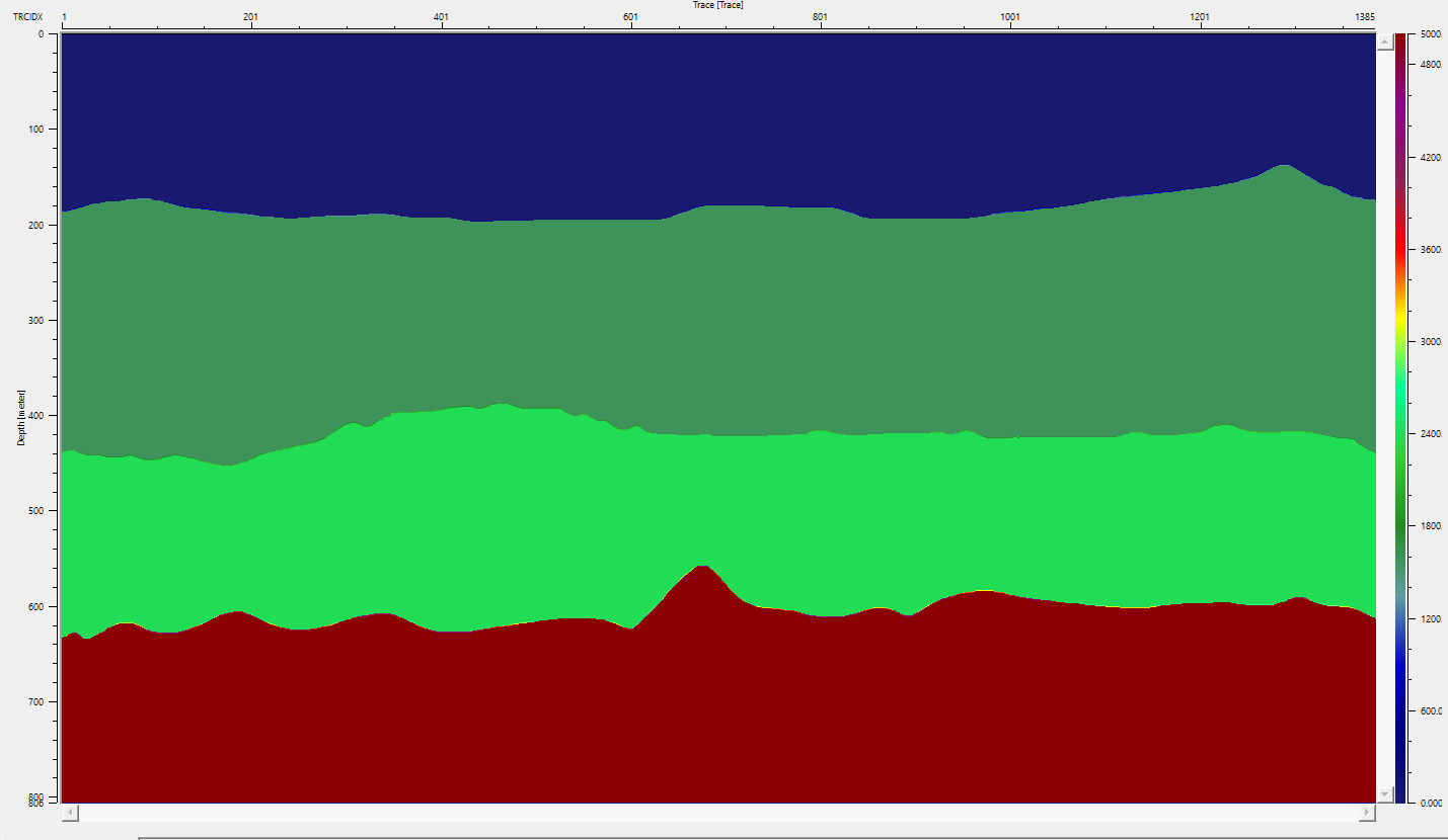
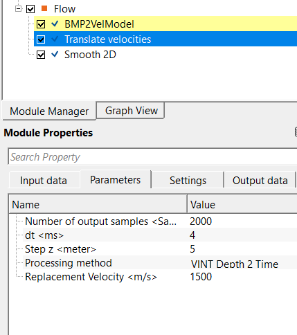
Further, the user can use "Translate velocities" module to translate this Depth velocity model into different velocity formats like RMS, Interval (Time) etc.
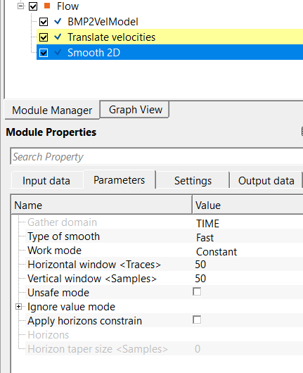
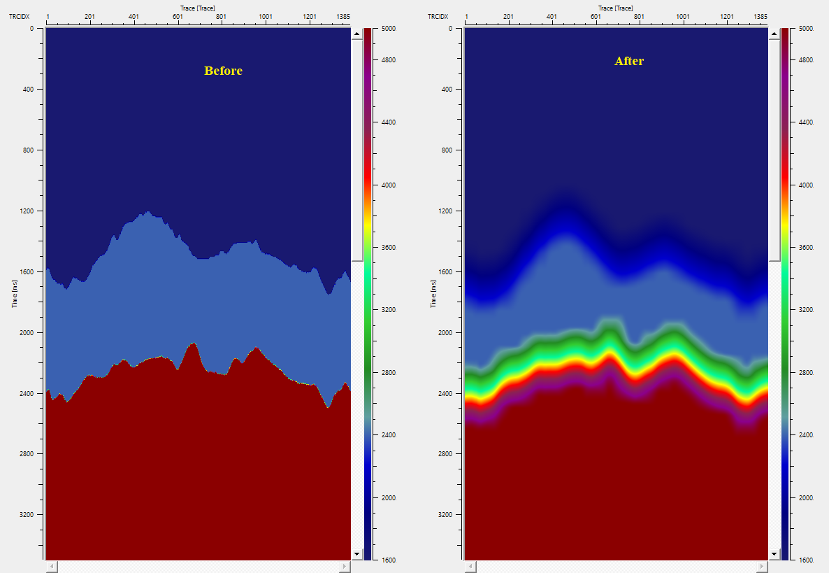
Later, this converted velocity model can be smoothed using Smooth 2D or any other module.
![]()
![]()
There are no action items available for this module so the user can ignore it.
![]()
![]()
YouTube video lesson, click here to open [VIDEO IN PROCESS...]
![]()
![]()
Yilmaz. O., 1987, Seismic data processing: Society of Exploration Geophysicist
 * * * If you have any questions, please send an e-mail to: support@geomage.com * * *