Merging/combining two seismic gathers (pre & post stack)
![]()
![]()
Merging seismic gathers requires matching geometry, sampling, amplitude, and phase so two datasets behave like a single continuous volume in both pre- and post-stack domains.
Pre-Stack Seismic Gathers (Shot / Receiver / CMP Gathers)
Purpose
•Combine acquisition patches
•Merge surveys from different vintages
•Create continuous coverage before processing
•Restore missing or incomplete gathers
Requirements / Steps
1.Match geometry
oRebuild or reorganize headers
oEnsure consistent SP, RP, CMP numbers
oEnsure identical coordinate reference system (CRS)
2.Match sampling parameters
oSame sample interval (dt)
oSame record length
oSame number of samples
3.Match trace headers
oSequence numbers
oOffset
oSource & receiver positions
oCDP (CMP) locations
oAzimuth, fold, channel numbers
4.Match amplitude & phase
oApply amplitude scaling
oPhase rotation if needed (phase comparison QC)
5.Sort to common domain
Example: sort both datasets to CMP gathers or shot gathers before merging.
6.Concatenate gathers
oAppend in the correct order
oRebuild trace sequence numbers
oCheck for duplicates or missing traces
7.QC
oFold map
oOffset distribution
oTrace continuity
oPhase and amplitude consistency
Post-Stack Seismic Gathers (2D/3D Volumes)
Purpose
•Splicing two seismic lines
•Merging 3D volumes from different surveys
•Extending survey coverage
•Time-lapse comparisons
Key Requirements
1.Coordinate alignment
oSame CRS / projection
oSame bin size (inline & crossline spacing)
oSame grid orientation / azimuth
oSame starting inline/crossline numbers
2.Vertical consistency
oSame sample rate (dt)
oSame time/depth domain
oSame datum and static corrections applied
oSame filter phase (zero-phase / minimum-phase)
3.Amplitude balancing
oAGC / RMS balancing
oSpectral balancing
oMatch energy between volumes
oPhase matching if needed
4.Phase consistency
oUse phase comparison
oApply global or local phase rotation
oEnsure interpretable continuity across merge zones
5.Blending or Feathering
oSmooth transitions in overlapping areas
oReduce boundary artifacts
oUse weighted averaging in overlaps
6.Grid Resampling
oResample both datasets onto the same grid
oUse interpolation (nearest, bilinear, spline)
7.Final merge
oMosaic the two volumes into one consistent cube
3. Common Problems When Merging Gathers
•Different CRS (UTM/WGS/Everest)
•Different bin size or survey azimuth
•Time shift mismatch
•Phase mismatch
•Amplitude mismatch
•Different processing sequences
•Overlapping zones with seams
•Trace misalignment or geometry conflicts
4. QC After Merge
•Check continuity of reflectors
•Examine amplitude and phase consistency
•Inline/crossline continuity
•Histogram match
•Spectrum match
•Fold & coverage maps (pre-stack)
![]()
![]()
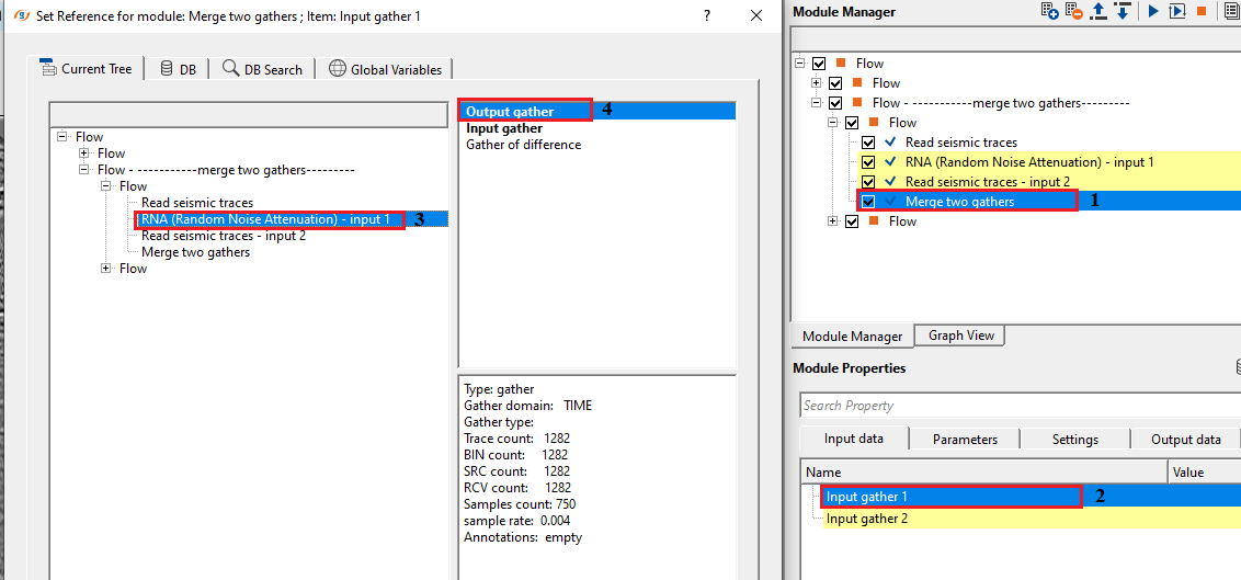
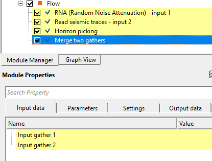
Input gather 1 - connect/reference to the Output gather of 1st input gather
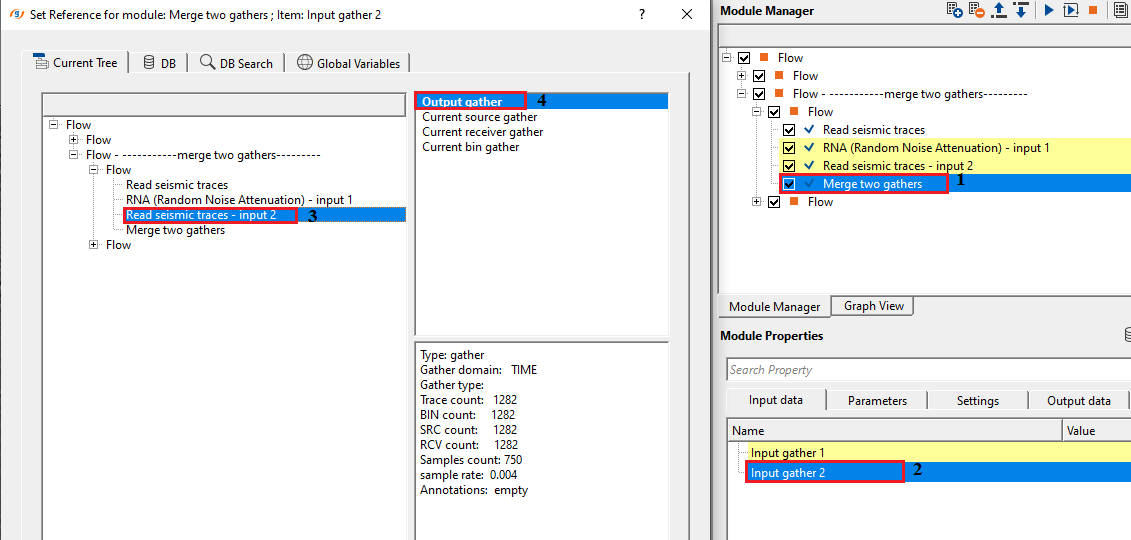
Input gather 2 - connect/reference to the Output gather of 2nd input gather for merging
![]()
![]()
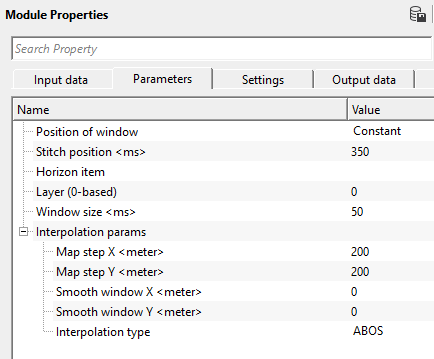
Position of window { Constant, Variable } - select the options from the drop down menu.
Stitch position - provide the position where it should be merged.
Horizon item - in case the position of window is variable, then the user should provide the horizon. Connect/reference to the output horizon(s).
Layer (0-based) - by default, 0.
Window size - specify the position of the window size. By default, 100.
Interpolation params - this section deals with the horizon interpolation.
Map step X - provide the step size in x direction
Map step Y - provide the step size in y direction
Smooth window X - provide the smoothing window size in x direction
Smooth window Y - provide the smoothing window size in y direction
Interpolation type { ABOS, Kriging } - choose the interpolation type from the drop down menu. By default, ABOS.
Interpolation type - ABOS - Artificial Bounded Object Structure or ABOS is a specialized interpolation method where it uses an artificial bounded structure like network of polygons to model and interpolate the elevations information to create the topography map.
Interpolation type - Kriging - is a statistical interpolation method based on the assumption that the spatial data points are correlated. It creates an optimal surface that minimizes prediction errors by considering both the distance between data points and their spatial correlation.
Kriging covariance type { Exponential, Spherical, Gaussian } - select the kriging covariance type from the drop down menu.
Exponential - This can be used where the subsurface properties change abruptly over small distances.
Spherical - The Spherical model is useful when the data exhibits a more gradual spatial correlation up to a certain range and then behaves independently beyond that range. When subsurface structures have coherent properties within a certain distance but lose coherence at greater distances.
Gaussian - The Gaussian model is often applied in cases where there is a long-range, gradual spatial dependence between data points. It’s suitable for data where the spatial dependence does not drop off abruptly, such as when seismic properties gradually change over larger distances or in homogenous subsurface areas.
Kriging range - If two data points are closer than the kriging range, they are considered spatially correlated and will influence each other's estimated values. If the distance is greater than the range, their influence on each other will be ignored. If the distance between two data points is more than 500 then it assumes that the data beyond that limit there is no correlation
Kriging number of points - Total number of data points used to estimate/interpolate the unknown point/sample. The more the kriging points the better result however the computation time also increase with this.
![]()
![]()
Skip - By default, FALSE(Unchecked). This option helps to bypass the module from the workflow.
![]()
![]()
Output gather - generates the merged output gather.
There is no information available for this module so the user can ignore it
![]()
![]()
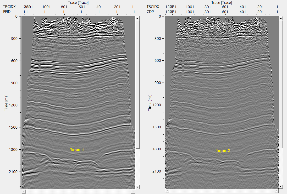
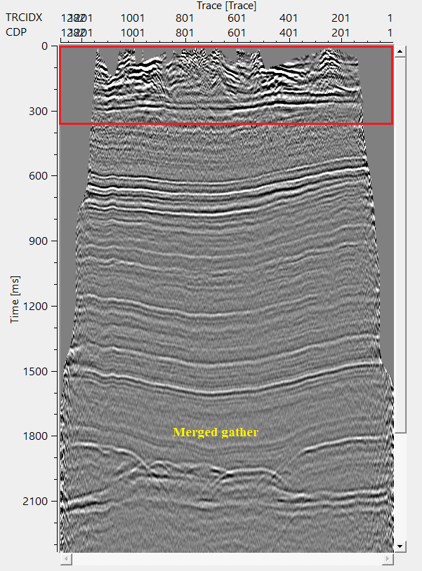
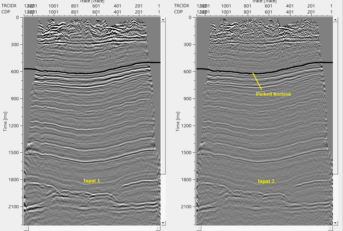
In this example workflow, we are working on two post stack data sets. Both the datasets must have same number of channels/fffid/sps/, record length, sample interval etc.
In this exercise, we are applying a random noise attenuation procedure on one of the dataset and the 2nd dataset is having little noise in the shallow region. We would like to merge the random noise attenuated output with the 2nd input data at a certain time.
Also, in this workflow, we are covering both the options of constant and variable Position of the window. In case of the constant, it is a standard procedure of providing the time at which the merge takes place. In case of the variable, the user needs to provide the horizon information. Based on the horizon, it will perform the merging.
Constant
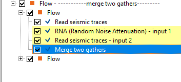
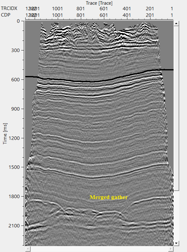
In the above example workflow, RNA output gather is considered as Input 1 & Read seismic traces module output gather is considered as Input 2.
Make the necessary references/connections to Merge two gathers modules.
Setup the parameters as per the requirement and execute the module.
Variable
In case of the variable position of the window, the user MUST provide the horizon information. If the user has an existing horizon then it can be called by using load item. Otherwise, the user has to pick the horizon using "Horizon picking" module and provide the output horizon to the Horizon item parameter.
Make the necessary reference/connections as mentioned in the previous section (Constant). Next go to parameters, and change the position of the window from Constant to Variable. Later, connect/reference the Horizon item to Output horizons of Horizon picking module.
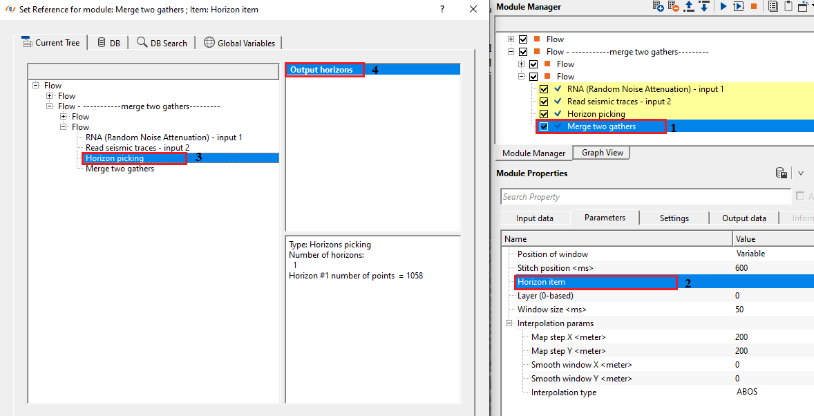
In this exercise, we are merging both the gathers at 600 ms with horizon as a control item.
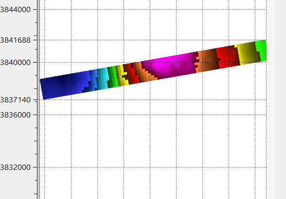
After executing the workflow, it will generate a interpolated horizon map.
![]()
![]()
There are no action items available for this module.
![]()
![]()
YouTube video lesson, click here to open [VIDEO IN PROCESS...]
![]()
![]()
Yilmaz. O., 1987, Seismic data processing: Society of Exploration Geophysicist
 * * * If you have any questions, please send an e-mail to: support@geomage.com * * *
![]()
Description
This module is used for merging tow gathers.
Parameters
Position of window
Choose the options of Constant or Variable window.
If the Position if window is Variable then the user should provide the horizon file information.
Stitch position
Provide the position where it should be merged.
Window size
Provide the window size.