Matched conversion uses cross-correlation to measure misalignment and convolution to apply the computed operator that matches the target to the reference.
![]()
![]()
Matched Conversion is a process used to align the phase, timing, and amplitude of one seismic dataset with another. It ensures two seismic volumes behave like they came from the same processing sequence, even if they originally did not.
We use matched conversion when:
•Merging two vintage seismic surveys
•Aligning near-angle, mid-angle, and far-angle stacks
•Matching baseline vs monitor (4D time-lapse)
•Matching seismic to a synthetic
•Comparing pre- and post-processed volumes
•Aligning legacy and reprocessed seismic
Matched conversion outputs:
•Time-aligned traces
•Phase-aligned signals
•Amplitude-balanced wavelets
Matched conversion adjusts one volume so that it “matches” another in phase, time, and amplitude.
How Matched Conversion Works?
1.Select a reference seismic volume (the trusted dataset).
2.Select the target dataset (the one to be modified).
3.Compute:
oCross-correlation
oWavelet difference
oPhase errors
oTime shift errors
4.Solve for the best filter + time shift that makes the target match the reference.
5.Apply the correction to the entire target dataset.
The principle uses cross-correlation to estimate the required time shift and wavelet operator, and convolution to apply the operator to the target data.
First - Cross-Correlation (for estimating time shifts)
Before applying any filter, the algorithm must determine:
•How much the target trace is shifted in time
•Whether the target needs upward/downward vertical shift
•Rough phase differences
This is done using cross-correlation, because, Cross-correlation tells us how similar two signals are as we shift one over the other.
It finds the time lag at which the two traces match best. This is controlled by the parameters:
•Min vertical shift
•Max vertical shift
Second - Solve for Matching Operator (Inversion)
Now the algorithm must compute a filter that transforms the target wavelet into the reference wavelet. This is a linear inversion, usually solved by:
•SVD
•Cholesky
•LSQR
The inversion solves:
![]()
Where:
•x = target trace
•y = reference trace
•h = filter/operator
This step requires a matrix equation. This is where λ (lambda) is used for regularization (stability).
Final - Convolution (to apply the filter)
Once the operator h is computed, the target trace is convolved with the operator.
![]()
The computed operator (wavelet correction filter) is convolved with the target seismic data to match phase, amplitude, and time characteristics.
![]()
![]()
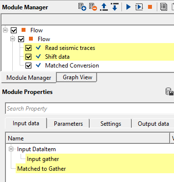
Input DataItem
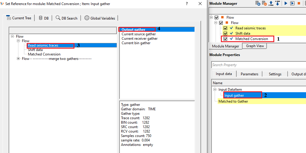
Input gather - connect/reference to the input gather that needs to be matched.
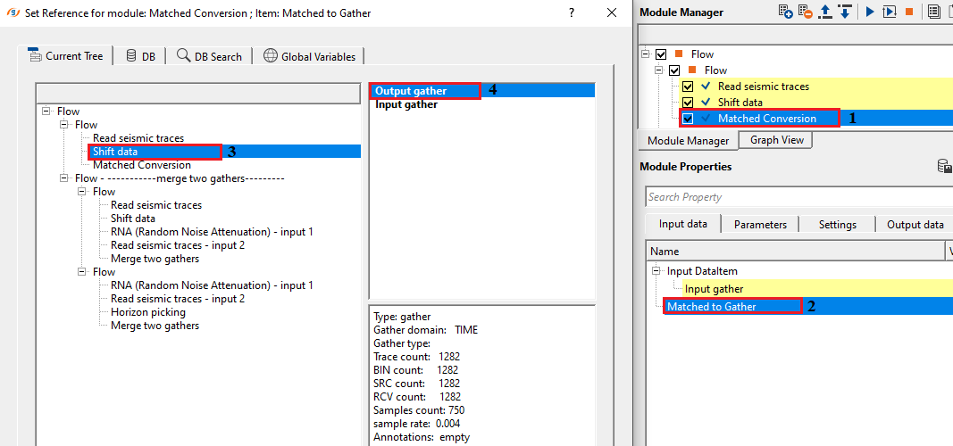
Matched to Gather - connect/reference to the matched gather that will be used as a matched gather for input gather.
![]()
![]()
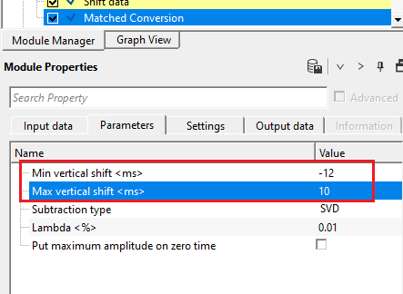
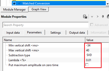
Min vertical shift - provided the minimum vertical shift for the data matching
Max vertical shift - providing the maximum vertical shift limit for the data matching
Subtraction type { SVD, Cholesky, Lsqr } - select the appropriate subtraction type from the drop down menu. By default, Cholesky.
Singular Vector Decomposition (SVD): This method in adaptive subtraction works by decomposing the seismic data matrix into singular vectors and values, then separating the primary signal (high-rank components) from unwanted noise or multiples (low-rank components). By removing or filtering out the low-rank components and reconstructing the data, SVD helps to enhance the primary signal while suppressing multiples or noise .
Cholesky - Cholesky Decomposition: In the Cholesky subtraction method, the primary idea is to use the Cholesky decomposition of the auto-correlation matrix of seismic data to model and subtract multiples from the observed data. The method leverages the correlation structure between seismic traces to isolate and remove these unwanted noise/multiples, thus enhancing the clarity of the primary reflections for further interpretation.
Lsqr - Least Square method is an adaptive filtering technique used to estimate and subtract unwanted signals such as multiples or noise. It involves solving a least squares optimization problem to find the best-fit unwanted signal model, which is then subtracted from the observed data to recover the primary seismic signal. The method is flexible, data-driven, and effective for removing complex unwanted components, but it can be computationally demanding and dependent on the quality of the input data.
Lambda - This is a regularization parameters where it is used to control the balance between fitting the data and suppressing the noise/multiple data.
When the estimated multiples are less sensitive to the small variations, a large Lambda value gives more weight to the regularization term which leads to smoother solution. Whereas in the case of lesser Lambda value, the estimated multiples are closely fitted/matched with the input data however this will increase the noise levels also.
Put maximum amplitude on zero time - specify the maximum amplitude value to be considered at the time zero. By default, FALSE (Unchecked).
![]()
![]()
Auto-connection - By default, TRUE(Checked).It will automatically connects to the next module. To avoid auto-connect, the user should uncheck this option.
Bad data values option { Fix, Notify, Continue } - This is applicable whenever there is a bad value or NaN (Not a Number) in the data. By default, Notify. While testing, it is good to opt as Notify option. Once we understand the root cause of it,
the user can either choose the option Fix or Continue. In this way, the job won't stop/fail during the production.
Notify - It will notify the issue if there are any bad values or NaN. This will halt the workflow execution.
Fix - It will fix the bad values and continue executing the workflow.
Continue - This option will continue the execution of the workflow however if there are any bad values or NaN, it won't fix it.
Number of threads - One less than total no of nodes/threads to execute a job in multi-thread mode. Limit number of threads on main machine.
Skip - By default, FALSE(Unchecked). This option helps to bypass the module from the workflow.
![]()
![]()
Output DataItem
Output gather - generates output gather as well as output gather as a vista item
Output operator - generates output matched operator as a vista item
There is no information available for this module
![]()
![]()
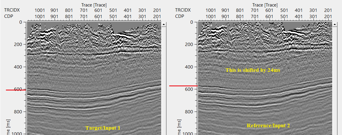
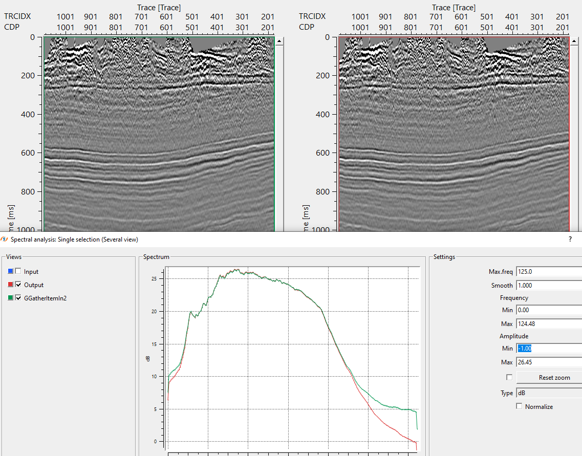
In this example workflow, we've two datasets with different characteristics. One input dataset (target) needs to be matched with a second input dataset (reference).
Input dataset 2 (reference) is shifted by a constant value and having a better signal to noise ratio. Our objective is to match the input dataset 1 with input dataset 2.
In the above example workflow, Input gather is shifted by a constant value of 24ms. Shifted gather is considered as reference gather.
Input gather is considered as a target.
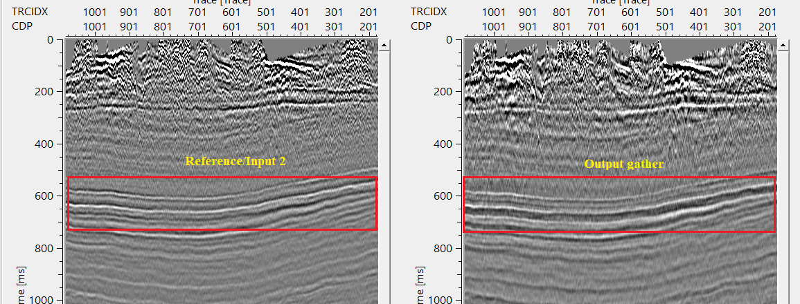
If we look at both the input(s) gathers, i.e. target and reference. Reference is shifted by 24ms marked as RED line on both the sections.
Adjust the cross-correlation parameters to find out the suitable time shifts by providing the minimum and maximum vertical shift values in the parameters tab.
This is the range that is allowed to check for the correlation.
If the minimum and maximum vertical shift values are less than the actual shift applied to the reference gather then it will work on the phase and try to match/change the phase of the input data.
In case the minimum and maximum vertical shift is equal or greater than the shift applied to the reference data then it will work with the time shift and try to match the target with the reference gather by calculating the Operator.
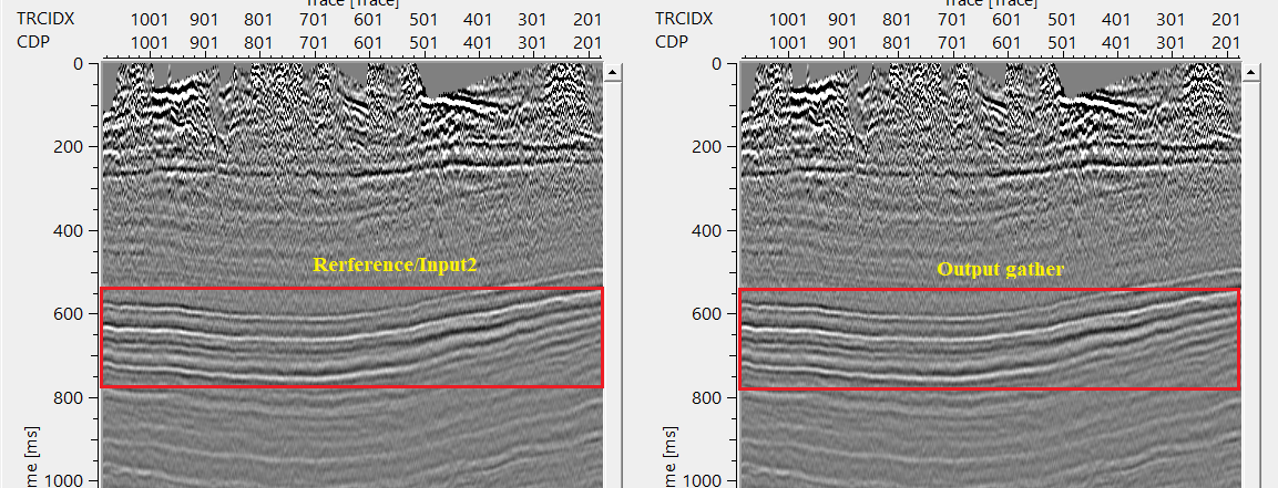
So the user has to pay attention to the minimum and maximum vertical shift values to get the correct matched output gather. In the above image, Output gather is matching with frequency, amplitude etc.
![]()
![]()
There are no action items available for this module
![]()
![]()
YouTube video lesson, click here to open [VIDEO IN PROCESS...]
![]()
![]()
Yilmaz. O., 1987, Seismic data processing: Society of Exploration Geophysicist
 * * * If you have any questions, please send an e-mail to: support@geomage.com * * *
![]()