Thomsen anisotropic parameter Epsilon picking (PSDM stage)
![]()
![]()
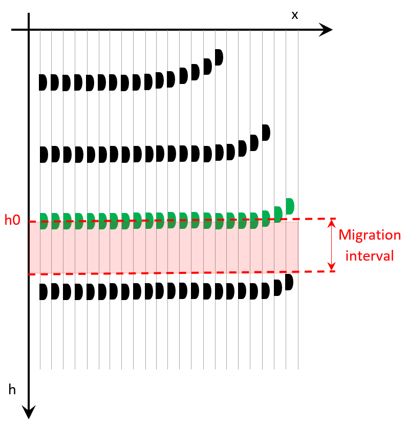
The primary function of this module is to estimate and manually pick the Epsilon attribute, a key parameter in evaluating rock anisotropy, specifically within the Vertical Transverse Isotropy (VTI) model. Epsilon, as defined by Thomsen’s anisotropy parameters, describes the difference between the horizontal and vertical velocities of Primary (P-Wave) seismic waves and plays a crucial role in refining seismic interpretations.
To support the manual picking of the Epsilon attribute, the module performs the calculation of seismic wave travel times based on input interval velocities and conducting a migration process for selected points (grid) with adjustments to the velocity model. The migration process involves varying the velocity law by applying percentage changes above and below 100% of the initial velocity model, helping to assess the impact of these variations on the seismic data. While these tasks are important for accurately estimating Epsilon, they serve as supporting functions to the core objective of Epsilon evaluation.

Epsilon is a key Thomsen parameter used to characterize anisotropy in rocks. In g-Platform, the VTI epsilon estimation module is specifically designed to calculate and facilitate the manual picking of this anisotropic parameter. The Epsilon attribute has a significant impact on far-offset velocities and is integral in understanding the anisotropic properties of the subsurface. By manually picking the Epsilon values, users can refine the velocity model, which in turn enhances the accuracy of seismic imaging and interpretation in anisotropic environments.
Module performs 3 steps: time table calculation, pre stack depth migration for grid (analysis points), manual picking.
![]()
![]()
Input requirements for estimating Epsilon:
1. Input vertical velocity model - this is should at final datum, from Delta and V vertical calculation module;
2. Delta model - this should also be at final datum, from Delta and V vertical calculation module;
3. Well tied horizons - output horizons from Delta and V vertical calculation module.
Depth velocity in - connect input interval velocity (V-vertical) gather that was used after well-tie process.
Delta param in - connect input Delta Thomsen parameter gather that was used for depth migration process.
Initial epsilon param in - connect input initial Epsilon Thomsen parameter gather, if it was already picked previously, or usually it is ZEROed gather (for example modify Delta = 0 via Expression calculator module).
Depth horizons - connect input horizon for migration only the interval around this horizon up/down in accordance with parameters (Shift up from layer to analyze, Shift down from layer to analyze). For example, this input horizon item can be created by Convert time horizons to depth horizons module.
Input SEG-Y data handle - connect input seismic data set, it's gather before migration (because this module does migration process).
Input data trace headers - connect input trace headers of the seismic data set, it's gather before migration (because this module does migration process).
Input trace data handle - optionally, in case Use trace vector on disk is enabled (avoid uploading trace headers into RAM, so it's not so quick, but it saves RAM), connect input trace headers of the seismic data set, it's gather before migration (because this module does migration process).
EPS picking item - pay attention it is an output epsilon picking item.
Use trace vector on disk - use this option in case trace header data (vector) is large for unloading it to the RAM. Therefore all trace headers will be uploaded directly from the disk without using necessity to use RAM.
![]()
![]()
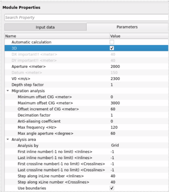
Automatic calculation - calculation all horizons and automatic picking of Epsilon values.
3D - enable in case input seismic data is 3D.
DX important!! - bin size X distance (CMP interval) in meters, it is better to define it manually in accordance with read value from the seismic data (without big number of decimal places, for example 12.5 is good, 12.49002345 is bad). Also, this value is updated automatically when you connect input velocity in the Input data tab (be careful if you would like set distance manually!).
DY important!! - bin size Y distance (CMP interval) in meters, it is better to define it manually in accordance with read value from the seismic data (without big number of decimal places, for example 12.5 is good, 12.49002345 is bad). Also, this value is updated automatically when you connect input velocity in the Input data tab (be careful if you would like set distance manually!).
Aperture - migration aperture (half of the distance!).
Datum - datum plane in meters. Note that the datum plane for depth velocity model will be set above the maximum elevation of the topography. This means that ray tracing will begin from this constant (horizontal) line, then pass through the topography, and continue further.
V0 - provide the replacement velocity m/s.
Depth step factor - 1 means no depth scale coefficient. A value greater than 1 enables depth scaling, which minimizes time consumption for timetable calculation. That is, the deeper the depth, the more sparse the travel time points are in the timetable:
Migration analysis - parameters for migration process:
Minimum offset CIG - minimum offset for migration, in meters.
Maximum offset CIG - maximum offset for migration, in meters.
Offset increment of CIG - increment offset for migration, in meters.
Decimation factor - minimum offset for migration.
Anti-aliasing coefficient - is a parameter used to prevent aliasing artifacts during the migration process, particularly when data is sampled at a resolution that is insufficient to accurately represent high-frequency wavefields. Aliasing occurs when higher-frequency components are incorrectly reconstructed as lower frequencies due to undersampling, which can distort the final seismic image. The anti-aliasing coefficient helps mitigate this issue by applying frequency-dependent filtering during the migration process. Choose between 0 and 1. Zero means no anti-aliasing.
Max frequency - the maximum frequency to include the imaging process.
Max angle aperture - the maximum angle (limits) for migration operator.
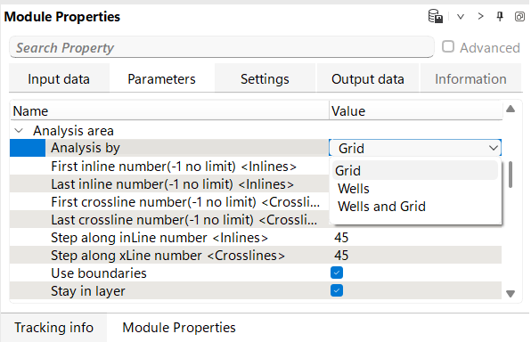
Analysis area - analysis point definition:
Analysis by - select option for point creation by: grid, wells, grid + wells. Grid means that only the following parameters will be used for analysis point creation first inline and last inline numbers, first xline and last xline numbers as well as their steps. Well creates analysis points only in well locations, i.e. 1 well in the project 1 analysis point will be created. Grid + wells obviously creates mix of two options: grid points + well's points together:
First inline number(-1 no limit) - first inline number of the points for ray path initializations. Starts from 1. Use Visual vista item for QC.
Last inline number(-1 no limit) - last inline number of the points for ray path initializations. Starts from 1. Use Visual vista item for QC.
First crossline number(-1 no limit) - first xline number of the points for ray path initializations. Starts from 1. Use Visual vista item for QC.
Last crossline number(-1 no limit) - last xline number of the points for ray path initializations. Starts from 1. Use Visual vista item for QC.
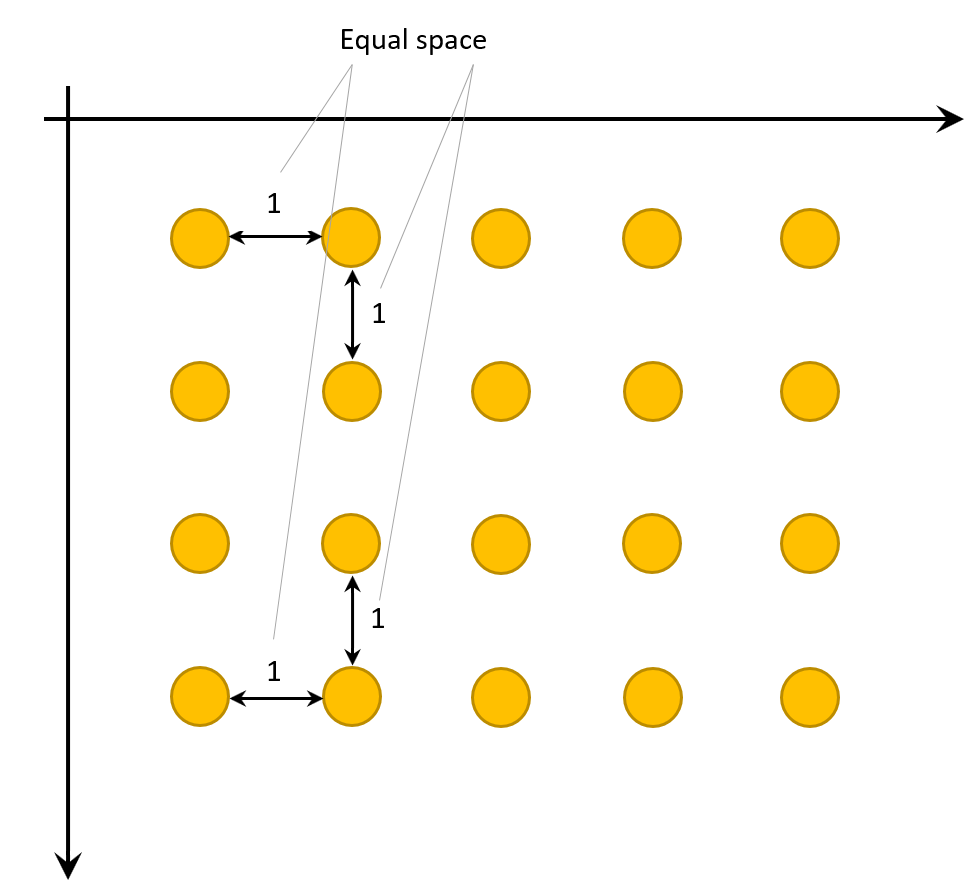
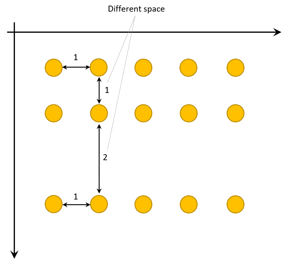
Step along inLine number - decimation step in inline numbers.
Step along xLine number - decimation step in xline numbers.
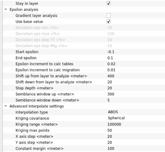
Epsilon analysis - types of epsilon analysis (Gradient layer analysis and Use base value), limits, deviations:
Gradient layer analysis - flexible type of epsilon perturbation, i.e. multivariate parametrization.
Deviation eps min - percentage of epsilon deviation or perturbation to the minimum direction from 100%, i.e. 95, 90, 85, ...
Deviation eps max - percentage of epsilon deviation or perturbation to the maximum direction from 100%, i.e. 105, 110, 115, ...
Deviation eps step TT - percentage step for travel time table calculation/perturbation.
Deviation eps step Mig - percentage step for migration calculation/perturbation.
Use base value - simple type of epsilon perturbation, i.e. basic parametrization.
Start epsilon - value of epsilon for perturbation start.
End epsilon - value of epsilon for perturbation end.
Epsilon increment to calc tables - percentage step for travel time table calculation/perturbation.
Epsilon increment to calc migration - percentage step for migration calculation/perturbation.
Shift up from layer to analyze - depth interval in meters that will be calculated, i.e. migration perturbation from the current horizon above (up):
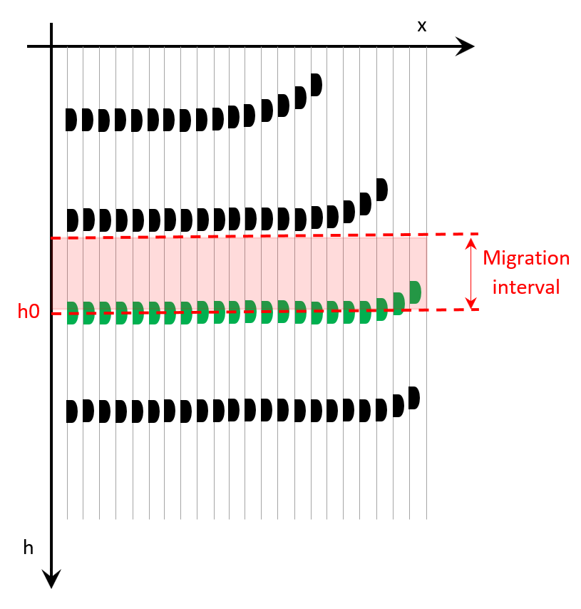
Shift down from layer to analyze - depth interval in meters that will be calculated, i.e. migration perturbation from the current horizon below (down):
Step depth - depth interval in meters of the resulting common image gather.
Semblance window up - depth interval in meters that will be calculated for epsilon semblance, i.e. migration perturbation from the current horizon above (up).
Semblance window down - depth interval in meters that will be calculated for epsilon semblance, i.e. migration perturbation from the current horizon below (down).
Advanced interpolate settings - explanation:
Interpolation type - minimum offset for migration.
Kriging covariance - defines the spatial correlation model used in Kriging. Available types: Spherical, Gaussian, and Exponential.
Kriging range <meter> - specifies the range of influence for spatial correlation in the Kriging model. A larger range results in smoother interpolation, while a smaller range captures more local variations.
Kriging max points - defines the maximum number of data points considered in the interpolation process for estimating unknown values. Increasing this value improves accuracy but may increase computation time.
X axis step - determines the grid resolution in the X direction for interpolating horizon maps. A smaller step size increases detail but requires more processing power.
Y axis step - defines the grid resolution in the Y direction for horizon interpolation. Like the X step, a finer resolution provides more detail but demands more computational resources.
Constant margin - expand map for picket creation; recommendation is use default value.
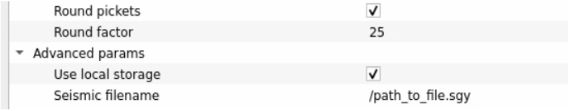
Round pickets - enable option for round pickets; recommendation is use default value.
Round factor - common round number; recommendation is use default value.
Advanced params - additional parameters for saving perturbation gathers on disk:
Use local storage - path to the file for direct reading seismic data from nodes in case of distributed execution (parallel mode). It will make data transfer faster.
Seismic filename - if Use local storage is enabled, define a name of seismic file.
![]()
![]()
SegyReadParams - parameters for setting advanced parameters of reading seismic traces from disk:
Thread count (for SSD) - amount of treads for reading seismic traces from disk.
Bulk size (traces) - size of a chunk (data portion) for reading seismic traces from disk.
Execute on { CPU, GPU } - select which type of processor will be used for calculations: CPU or GPU.
Distributed execution - if enabled: calculation is on coalition server (distribution mode/parallel calculations).
Bulk size - chunk size is RAM in megabytes that is required for each machine on the server (find this information in the Information, also need to click on action menu button for getting this statistics):
Limit number of threads on nodes - limit numbers of of threads on nodes for performing calculations.
Job suffix - add an job suffix.
Set custom affinity - an axillary option to set user defined affinity if necessary.
Affinity - add your affinity to recognize you workflow in the server QC interface.
Number of threads - limit number of threads on main machine.
Run scripts - it is possible to use user's scripts for execution any additional commands before and after workflow execution:
Script before run - path to ssh file and its name that will be executed before workflow calculation. For example, it can be a script that switch on adn switch off remote server nodes (on Cloud).
Script after run - path to ssh file and its name that will be executed before workflow calculation.
Skip - switch-off this module (do not use this module in the workflow).
![]()
![]()
Epsilon param out - output epsilon Item.
Current CIGs in raw - current common image gather without epsilon.
Selected CIG gather - selected common image gather with epsilon.
V depth inline - velocity field (gather) section along inline direction.
V depth crossline - velocity field (gather) section along xline direction.
Delta depth inline - output Delta filed (gather) section along inline direction.
Delta depth crossline - output Delta filed (gather) section along xline direction.
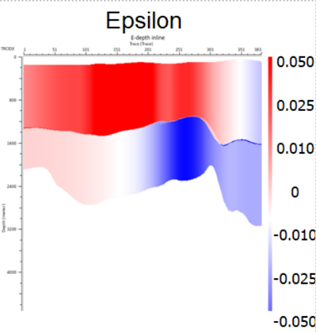
Epsilon depth inline - output Epsilon filed (gather) section along inline direction.
Epsilon depth crossline - output Epsilon filed (gather) section along xline direction.
Epsilon base depth inline - output Epsilon base filed (gather) section along inline direction.
Epsilon base depth crossline - output Epsilon base filed (gather) section along xline direction.
![]()
![]()
Reinit input data - use this function for re-initialization input data in case of some of input data sets were changed.
Update layer and velocity - press this button when the first layer is ready to update epsilon and velocity.
---------------------
Clear current layer epsilon picking - clear current epsilon layer.
Clear all epsilon picking - clear all epsilon layers.
Reset epsilon gather - reset epsilon gather.
---------------------
Move up - move up to the neighbor gather perturbation that is located on the northern part from the current one.
Move down - move down to the neighbor gather perturbation that is located on the southern part from the current one.
Move left - move left to the neighbor gather perturbation that is located on the western part from the current one.
Move Right - move right to the neighbor gather perturbation that is located on the eastern part from the current one.
![]()
![]()
At the input, the initial epsilon parameter receives the Delta attribute, which is used as the initial value for scanning the Epsilon values.
Read seismic data set before migration, velocity model, depth horizons, delta and initial (zeroed) epsilon.
![]() Pay attention!!! Use initial delta gather is zeroed gather, that can be created via Expression calculator module (input gather is Delta -> mathematical expression = 0)
Pay attention!!! Use initial delta gather is zeroed gather, that can be created via Expression calculator module (input gather is Delta -> mathematical expression = 0)

Steps in case of 2 layers (horizons):
1.Exec calculation for the 1st layer;
2.Pick CIGs – Epsilon 1;
3.Click on the verb Update layer and velocity for the 1st layer freezing and velocity update;
4.Exec calculation for the 2nd layer;
5.Pick CIGs – Epsilon 2.
Use sub-sequence for gather filtering.
The resulting CIGs are not the same as it is from PSDM module, so we can use light migration parameters for epsilon scanning (i.e. aperture, angle, …) for fast calculation.
Gather perturbations Visual Vistas:
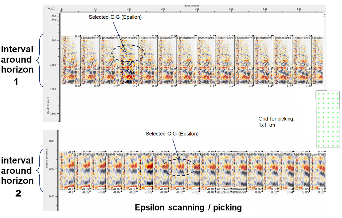
Final epsilon attributes with layers:
![]()
![]()
YouTube video lesson, click here to open [VIDEO IN PROCESS...]
![]()
![]()
 If you have any questions, please send an e-mail to: support@geomage.com