Description
High resolution radon spectrum multiple wave attenuation based on actual velocity field.
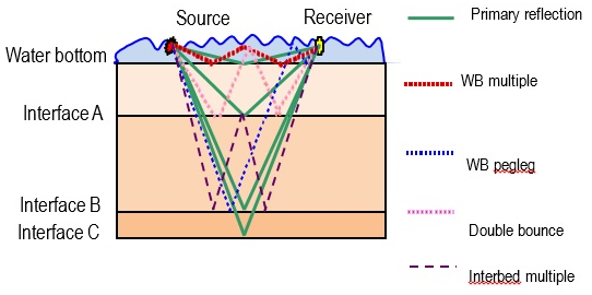
The presence of multiples in data can give false information to the interpreter, either by mis-stacking or as erroneous events in prestack gathers. To attenuate the multiples we need an algorithm which can predict the multiples from the input data and then subtract the multiples to provide multiple attenuated data. It can be accomplished using two different approaches:
1.Periodicity based
2.Move out base

Interbed multiples can have a large velocity difference as compared to the primary reflections at the same recorded time. That move out difference can be used for multiple attenuation with a Tau-P transform approach.
This module is used for multiple attenuation in unstacked NMO (normal move out) corrected seismic gathers.
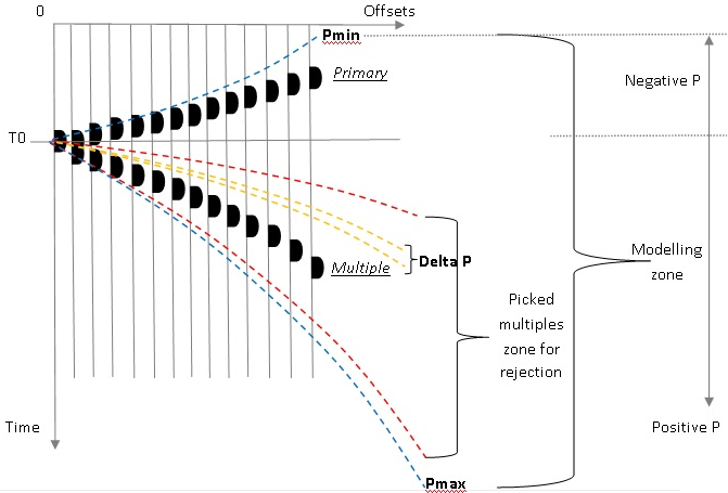
An unstacked seismic common-midpoint gather can be described in terms of slope dt/dx = P and intercept time t0, where t gives the two way time of a sample in the gather, x is the source – receiver offset distance, and t0 is the zero offset time of a particular event. The transform process used to model and remove multiples is called the Radon transform. The Radon transform distinguishes between primaries and multiples based on the residual move out from near to far offset on NMO corrected gathers. NMO corrected gathers will align all of the primary energy near P=0, that is with increasing offset x the observed t values are near t0. Multiple energy should be expected to have more variation in the value of t as compared to the t0 values, the observed P-values should be differentiable as compared to the primary energy by the Radon transform. Larger move out differentials will lead to a more effective Radon filter as it is easier to differentiate the primary data from the multiple data.
The module computes a multiple model and a primary model. This procedure is based on decomposing the input seismic gathers into user-defined parabolas using an anti aliasing least-squares method with high resolution. Events with a higher slope value (larger t values as compared to t0) are treated as multiples. Events with a smaller slope (t values close to t0) are identified as primary reflections. The user defines the boundary between multiple and primary data as a percentage of the primary velocity.
Input data
Input DataItem
Geometry assigned CMP Gathers
Sort the data in cmp/offset or cmp/abs_offset
Input gather
Velocity model
External velocity model
Parameters
Time-Velocity factor
Time/Percent of primary velocity table defines border between primary and multiple
Enable QC windows
Create velocity spectra & Tau-P domain visualization before/after multiple attenuation. Useful for testing & QC but takes more machine resources
Radon params

P min
Minimum p-value for transform data from t-x into tau-p domain
P max
Maximum p-value for transform data from t-x into tau-p domain. This parameter is end for modeling multiple waves.
Delta P
Amount of modeling waves. Should be approximately equal signal response time interval.
Taper P
Taper zone between P min/mid/max-values
Taper Tau
Taper zone between start time - filtered - end time
Velocity
Stretch factor
Stretch factor for gathers & semblances
Smoothing parameter Y velocity
Semblance smoothing over the y axis, in number of samples
V0
Replacement velocity value used for accurate NMO implementation
Normalization window
Normalization for semblance
Semblance start velocity
Beginning of velocity range covered by the semblance
Semblance ending velocity
End of velocity range covered by the semblance
Semblance velocity step
Velocity resolution for the semblance
Semblance smooth window
Smoothing parameter for semblance display
Optional
Frequency min
Minimum frequency for filtering
Frequency max
Maximum frequency for filtering
Pre-Whitening Factor
Pre-whitening factor for stabilizing tau-p to t-x transformation.
Use AGC
Apply automatic gain control pre radon filtering and remove after radon filtering
AGC Window
Window for automatic gain control
First arriving cut protection length
Length above first arriving by velocity model to prevent data cancellation