Description
Data Enhance - 3D CO-MF enhances 3D pre-stack seismic data by performing partial stacking within a spatial and offset-class aperture, guided by Common Offset MultiFocusing (CO-MF) kinematic parameters stored in a pre-computed database (.kdb file). Each output trace is formed by coherently summing nearby input traces whose traveltimes are corrected using the optimal MultiFocusing operator for that imaging point, improving signal-to-noise ratio while preserving offset and azimuth information.
Because the MultiFocusing approach does not require CMP symmetry, this module can also regularize irregularly sampled 3D data: output traces can be placed at any target imaging point within the acquisition area, even at locations not occupied by actual CMP midpoints. This makes it well-suited for both noise attenuation and trace interpolation on land and marine 3D surveys.
This module requires a 3D CO-MF database (.kdb) previously computed by the Engine - 3D CO-MF workflow. The input pre-stack data must be in g-Platform internal format (SEG-Y handle). The output is a new pre-stack dataset in g-Platform internal format (.gsd), with geometry defined by the output sorted headers and bin grid.
Input data
Output file name
Path to the output file that will receive the enhanced pre-stack data. The file is written in g-Platform internal format (.gsd). If the file already exists, the module can either overwrite it (Direct mode) or append new traces to it (Append mode), depending on the Write mode parameter. Choose a descriptive name that identifies the offset class, aperture settings, or processing pass used.
Storage file 3D-CO
Path to the 3D CO-MF database file (.kdb) produced by the Engine - 3D CO-MF module. This binary database contains all pre-computed MultiFocusing kinematic parameters — wavefront curvatures, emergence angles, and mute functions — organised by imaging point and offset class. The quality and spatial coverage of this database directly determine the quality of the enhancement. The database geometry (bin grid) must be compatible with the input seismic data geometry.
SEG-Y data handle
Connect the g-Platform data handle that provides access to the input pre-stack seismic data. This is the raw or pre-processed 3D dataset on which enhancement will be performed. The number of samples in this dataset must not exceed the number of time samples stored in the CO-MF database; if it does, the module will report an error at startup.
Input sorted headers(of seismic data)
Sorted trace header index (gather index vector) describing the geometry of the input pre-stack data — that is, the actual acquisition geometry of the raw seismic dataset. This must be sorted as a 3D CMP gather. The module uses this index to locate source and receiver positions of input traces that will be summed into each output bin.
Output sorted headers (of synthetic acquisition)
Sorted trace header index describing the target output geometry — the synthetic acquisition grid for which enhanced traces will be produced. This defines which CMP locations and offset classes will appear in the output dataset. It can be identical to the input geometry for noise attenuation, or it can specify a regularised, denser grid for data interpolation. Must be sorted as a 3D CMP gather.
Input BinGrid
The 3D bin grid defining the inline/crossline coordinate system of the input pre-stack dataset. This grid is used to translate CMP indices into real-world XY coordinates when searching for input traces within the specified distance apertures.
Output BinGrid
The 3D bin grid defining the inline/crossline coordinate system of the output enhanced dataset. This grid provides the XY positions of the target output bins listed in the Output sorted headers. It may have a different bin spacing or orientation from the Input BinGrid when the module is used for regularisation onto a new acquisition grid.
G3DPickingItem
Optional velocity picking constraint item (G3DPickingItem) that restricts the MultiFocusing parameters used during enhancement to those falling within a user-defined velocity corridor. When connected, only MF kinematic parameters whose associated stacking velocities fall within the picking corridor are accepted for each time sample, which prevents the summation from using physically unreasonable moveout corrections. If not connected, all parameters in the database are used without velocity filtering.
V0 Map
Optional 2D map (GMatrixItem) providing a spatially varying near-surface velocity V0 value. When connected, this map overrides a constant V0 for the MultiFocusing traveltime correction across the survey area, which improves enhancement quality in areas with strong lateral near-surface velocity variation. If not connected, the V0 value stored in the CO-MF database is used.
Parameters
Create NMO corrected gathers
When enabled, the output pre-stack dataset is produced in NMO-corrected form: each output trace has its traveltime moveout removed so that reflections appear flat across offsets. Default: off. Enable this option if you intend to use the output data for NMO-based stacking or for AVO analysis that requires flattened gathers.
MF emulation mute
When enabled, the module applies a mute that emulates the MultiFocusing stretch mute applied during the original MF engine calculation. This ensures that the enhanced data has the same muted zones as the stacked MF output, which is useful when the enhanced gathers will be compared directly to the MF stacked section. Default: off.
Image creation parameters
A group of parameters controlling how the MultiFocusing partial stack image is formed. These are the same parameters used in the MF Engine and govern how the azimuthal directions are handled, how many directions are used, and whether signal-to-noise enhancement is applied during the summation. The sub-parameters include:
Directions — number of azimuthal sectors into which the trace aperture is divided for the partial stack. Default: 1 (no azimuthal splitting). Increase this value for azimuth-sensitive processing such as fracture characterisation.
From Angle / To Angle — azimuthal range (degrees) within which input traces are accepted for the partial stack. Default: -90° to 90°. Narrow this range to isolate specific acquisition azimuths.
SN Enhance — when enabled, applies an additional signal-to-noise enhancement step within each azimuthal sector during the partial stack. Default: off.
Correlation Threshold — minimum inter-trace correlation coefficient (0–100%) required for a trace to be included in the SN-enhanced partial stack. Default: 10%.
Mute type
Selects how the MultiFocusing stretch mute is applied during the partial stack. The mute removes heavily stretched or distorted portions of the MF traveltime correction that would degrade stacking quality. Two options are available:
•Use mute factor– Will be used single value of MF mute function (see Parameterization-MF Engine)
•Use mute function–MF mute function will be taken from database and will be same as was used during MF calculation
Default: Use mute factor. Use Use mute function when you want the enhancement output to be fully consistent with the original MF engine run, using the spatially variable mute that was computed per imaging point.
MuteFactor
The single mute threshold value (in ms) applied when Mute type is set to Use mute factor. Traces for which the MultiFocusing time correction exceeds this value are excluded from the partial stack. Default: 1000 ms. Reduce this value to apply a stricter mute that protects short-period data from large MF stretches; increase it to allow more input traces to contribute at the cost of potentially including more stretched signal.
CO aperture mode
Controls how the common-offset aperture for trace selection is defined. Two modes are available:
XY aperture — input traces are selected based on their CMP midpoint distance to the output bin location, using the Max Distance to CS-CR parameter. This is the standard mode for most surveys.
Offset aperture — input traces are selected based on their source-receiver offset relative to the target offset class, rather than by XY distance. Use this mode for surveys with strong azimuthal offset variation where offset proximity is more meaningful than XY proximity.
Default: XY aperture.
Kill empty traces
When enabled, output traces that contain no contributing input data (all-zero traces resulting from an empty aperture) are suppressed and not written to the output file. Default: off. Enable this option to reduce output file size when the output geometry is sparser than the actual data coverage.
Interpolation properties
A group of parameters controlling the spatial interpolation method used to estimate MultiFocusing kinematic parameters at output bin locations that fall between stored CO-MF database imaging points. The interpolated parameters are then used to compute the traveltime correction applied to input traces during the partial stack.
Interpolation method
Selects the algorithm used to spatially interpolate the CO-MF kinematic parameters from database imaging points to output bin locations. Two options are available:
Triangulation — linear interpolation within Delaunay triangles formed by neighbouring imaging points. Fast and exact at data points; recommended for regularly-sampled CO-MF databases.
Kriging — geostatistical interpolation that honours the spatial covariance structure of the MF parameters. Produces smoother results than Triangulation in areas of irregular or sparse database coverage, at the cost of longer computation time.
Default: Triangulation.
Kriging covariance type
Selects the variogram model used when Interpolation method is set to Kriging. Options are Exponential, Spherical, and Gaussian. Default: Exponential. The Exponential model is appropriate for MF parameter fields that vary gradually with distance; the Spherical model suits datasets with a well-defined range of spatial correlation; the Gaussian model produces the smoothest interpolation and is best when the parameter field is very smooth.
Kriging range
The spatial correlation range (m) of the Kriging variogram model. Neighbouring CO-MF imaging points within this distance from the target output bin are used to estimate the interpolated MF parameters; points beyond this distance have negligible influence. Default: 100000 m. Set this to a value comparable to the typical spatial scale of MF parameter variation in your survey — typically several times the bin spacing of the CO-MF database grid.
Kriging number of points
The maximum number of nearest CO-MF database imaging points used in the Kriging interpolation for each output bin. Default: 15. Increasing this number improves interpolation stability in areas of sparse database coverage at the cost of computation time. Decreasing it speeds up processing in dense databases where nearby points are closely spaced.
Distance For Trace Selection
A group of parameters controlling which input traces (both raw seismic data and CO-MF database entries) are selected for processing each output bin. Proper tuning of these distances is critical for enhancement quality: too small an aperture reduces fold and may produce noisy output; too large an aperture may include traces from structurally unrelated areas and degrade lateral resolution.
MF Trace Selection
Sub-group of parameters that control which CO-MF database imaging points are accepted as sources of kinematic parameters for a given output bin. These parameters define the search radius in CMP space and offset space within the CO-MF database.
Max Distance To MF CMP
Maximum lateral distance (m) from the output bin CMP location to a CO-MF database imaging point for its kinematic parameters to be used in the enhancement. Default: 50 m. This controls how far the module looks into the MF database for applicable parameters. Set this value to approximately half the bin spacing of the CO-MF database grid to ensure that at least one database imaging point is always found near each output bin.
Max Distance To MF CO Trace
Maximum difference in source-receiver offset (m) between the output trace and a CO-MF offset class for the parameters of that offset class to be applied. Default: 1000 m. Set this to approximately half the offset-class step used in the CO-MF engine calculation to ensure the correct offset class is matched for each output trace. Narrowing this value enforces stricter offset matching; widening it allows parameters from adjacent offset classes to be used when the target offset falls in a gap.
Maximum number of used MF Bins
The maximum number of CO-MF database imaging points (bins) whose kinematic parameters are used in the interpolation for each output bin. Default: 8. Only the closest database imaging points (within Max Distance To MF CMP) up to this count are considered. Increasing this value improves interpolation accuracy at the cost of computation time; decreasing it speeds up processing in densely computed databases.
Raw Data
Parameters for selection of pre-stack seismic data that will be used for partial summation. There are 2 stages of data selection first in CMP domain and second in offset:
Decimation Factor
•Factor for data decimation with preservation of offset-azimuth distribution
An integer decimation factor applied to the input traces before the partial stack, while preserving the offset-azimuth distribution of the selected traces. Default: 1 (no decimation). Increasing this value reduces the number of input traces used per output bin, which speeds up computation on very dense 3D datasets at the cost of lower fold in the partial stack. A value of 2 uses every other trace; 3 uses every third trace, etc.
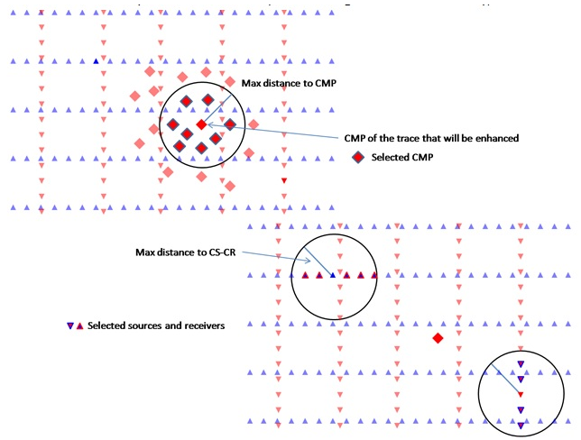
Max Distance To CMP
•Maximum distance from CMP location of the enhanced trace to the CMP that will be used for partial summation (first stage of trace selection)
Maximum lateral distance (m) from the output bin CMP location to the CMP midpoint of input raw traces in the first stage of trace selection. Default: 150 m. This is the primary spatial aperture for the enhancement. Set this value based on the expected lateral coherence length of the target reflectors — larger values increase fold and smooth the output more aggressively, while smaller values preserve finer lateral detail.
Max Distance To CS-CR
•Maximum distance from source and receiver of the enhancing trace to the source-receivers that will be used in partial summation (second stage of trace selection)
Maximum distance (m) between the source (and separately, receiver) position of the output trace and the source-receiver positions of input traces in the second stage of selection. Default: 100000 m (effectively unconstrained). Reducing this value enforces that only input traces recorded with sources and receivers physically close to those of the output trace contribute to the partial stack — useful for preserving azimuthal fidelity on wide-azimuth 3D surveys.
Symmetrical aperture
When enabled, the spatial aperture used for selecting input raw data traces is applied symmetrically around the output bin location — both updip and downdip azimuths are treated equally. Default: on. Disable this option only if you need to enforce asymmetric aperture constraints along a specific acquisition direction, such as when shooting in one direction only.
Use dynamic window
When enabled, the interpolation window length is applied dynamically: it starts from zero and is increased incrementally until the first non-zero amplitude value is found within the window. This prevents the module from computing zero-filled output traces when the static window misses valid data. Default: on. Disable this option only when a fixed interpolation window length is required for consistency testing or benchmarking.
Interpolation Window Length
The half-length (ms) of the time window used for the MultiFocusing coherency computation during the partial stack. Input traces are accepted for summation only if their MF-corrected time sample falls within this window of the target output sample. Default: 10 ms. Use larger values when the MF parameters are less accurate (coarse database grid, poor convergence) so that more input samples contribute; use smaller values when the database is well-constrained and high resolution is required.
Stabilisation Window Length
The half-length (ms) of the stabilisation time window applied after the partial stack to smooth amplitude discontinuities at the edges of the interpolation window. Default: 10 ms. This window reduces ringing artifacts that can appear at sample boundaries when input traces enter or leave the interpolation aperture. Increase this value if you see high-frequency noise introduced at the top or bottom of reflection events in the enhanced output.
Write mode
Controls how traces are written to the output file. Two options are available:
Direct — the output file is created from scratch (or overwritten) at the start of the run. Use this for a fresh enhancement run.
Append — new enhanced traces are appended to an existing output file. Use this when resuming a partially completed run or when merging results from multiple offset-class passes into a single output dataset.
Default: Direct. For more information on file writing behaviour, see the Save SEG-Y documentation.
Custom Actions
The following custom actions are available from the module context menu:
Show MF bins in storage — displays the set of CO-MF imaging points that are present in the connected database (.kdb file) as a point overlay in the 2D/3D viewer. Use this to verify the spatial coverage of the database before running the enhancement.
Show MF bins for calculation — displays only those CO-MF database imaging points that will actually be used given the current distance and aperture parameter settings. Use this to confirm that the trace selection parameters are reasonable before running the full enhancement.
Create stack — exports a zero-offset (stacked) section of the enhanced data to a SEG-Y file. This provides a quick quality-control view of the enhancement result without running a separate stack module.
Create output fold map — generates a 2D fold map showing how many input traces contribute to each output bin in the current aperture configuration. Review this map to identify under-illuminated areas where trace selection aperture may need to be widened.