Description
Data Enhance - 2D ZO-MF improves the signal-to-noise ratio of 2D pre-stack seismic data using the Zero-Offset MultiFocusing (ZO-MF) method. For each output bin location, the module reads the optimal MF wavefield parameters from the ZO-MF database, time-corrects nearby pre-stack traces using those parameters, and coherently sums them into an enhanced output gather. Because the MultiFocusing time correction does not require CMP symmetry, the output bin can be placed at any imaging point within the acquisition aperture — making this module equally useful for noise suppression and for data regularization and interpolation onto a new output geometry.
The module requires a ZO-MF database (.kdb) created by the Engine - 2D ZO-MF module. The raw pre-stack data is supplied via a SEG-Y handle together with real acquisition geometry (source-receiver index vectors). The output geometry defines where the enhanced gathers are placed. Velocity-constraint pickings and spatial polygons may optionally be provided to restrict or guide the enhancement process.
Execution is multi-threaded and supports distributed (remote) and GPU-accelerated processing.
Input data
Storage file 2D
The 2D ZO-MF database file (.kdb) generated by the Engine - 2D ZO-MF module. This binary database stores the MultiFocusing wavefield parameters — including semblance values, reflection times, and MF parameter indices — for every imaging point along the 2D line. The module reads these parameters to compute the time corrections applied during the partial stacking. This field is mandatory.
File with polygons
An optional polygon file (.polygon) that spatially restricts the area where data enhancement is performed. Only imaging points that fall within the defined polygon boundaries will be processed; all other output bins are skipped. Use this to limit computation to a region of interest or to exclude noisy zones from contributing to the enhanced output.
File with picking
An optional velocity-constraint picking file (.corr) that restricts which MF parameters are accepted during the partial summation. Only events whose MF parameters fall within the picked velocity corridors are included in the stack. This allows the user to suppress ground roll, multiples, or other coherent noise by excluding them from the enhancement aperture. If both this file and the G3DPickingItem connector are provided, the connector takes precedence.
Output file name
The path and file name for the output enhanced gather file (.gsd). The module writes one enhanced CMP gather per output bin to this file. The Write mode parameter controls whether an existing file is overwritten (Direct) or appended to (Append). This field is mandatory.
SEG-Y data handle
The input pre-stack seismic data connector. Connect the SEG-Y data handle from the project's pre-stack dataset. The sample interval and trace count are read from this handle and validated against the ZO-MF database to ensure compatibility. The raw traces from this dataset are used as the source data for the partial stacking process.
GRealGatherIndexVectorItem
The real acquisition geometry index vector. This connector carries the CMP-sorted index of the actual recorded data — it tells the module which physical source-receiver pairs exist in the dataset and where they are located. The module uses this geometry to assemble the super-gather of nearby traces for each output imaging point. The geometry must be sorted in 2D CMP order.
GVirtualGatherIndexVectorItem
The output (virtual) geometry index vector. This defines the set of bin locations to which the enhanced gathers will be written. For noise suppression on the original geometry, connect the same geometry as the real acquisition. For data regularization or interpolation, connect a regularly sampled output geometry that differs from the real acquisition. The geometry must be sorted in 2D CMP order.
G3DPickingItem
An optional velocity-constraint picking item connected directly from another module in the processing flow. When connected, this picking overrides any picking file specified in the File with picking field. The picking defines velocity corridors that constrain which MF events participate in the partial stack, allowing selective enhancement of specific wavefield components.
V0 Map
An optional near-surface velocity map (GMatrixItem) providing the reference velocity V0 used internally by the MultiFocusing kinematic corrections. When provided, the map spatially varies the reference velocity along the line, improving time-correction accuracy in areas with significant near-surface velocity variations. If not connected, V0 is taken from the ZO-MF database parameters.
Parameters
Create NMO corrected gathers
When enabled, the output pre-stack gathers are NMO-corrected using the MultiFocusing velocity parameters, so that reflections appear flat across offset. Enable this option when the enhanced gathers will be used directly for stacking, amplitude-versus-offset analysis, or other workflows that require moveout-corrected data. Default: disabled.
Image creation parameters
This parameter group controls how MF events stored in the ZO-MF database are selected and combined during the partial stacking. Each imaging point in the database may contain multiple events (reflectors arriving from different directions), each characterized by a semblance value, reflection time, and MF parameter indices. The following sub-parameters control which events are admitted and how they are weighted.
Directions — Maximum number of MF events (wavefield directions) included in the summation per imaging point and time sample. Increasing this value allows more complex multi-event wavefields to be preserved, but may also include weaker, noisier events. Default: 1.
From angle — Lower bound of the dip-angle range (in degrees) within which MF events are accepted. Events whose apparent dip angle falls below this threshold are excluded from the stack. Use this together with To angle to restrict enhancement to a particular angular sector of the wavefield. Default: -90°.
To angle — Upper bound of the dip-angle range (in degrees) within which MF events are accepted. Default: 90°.
SN enhance — When enabled, traces are weighted by their semblance values before summation, so higher-semblance (more coherent) events contribute more strongly to the output. This improves the signal-to-noise ratio of the enhanced gather but may reduce amplitude fidelity. Default: disabled.
Correlation threshold — Minimum semblance value (expressed as a percentage of the maximum semblance at that time sample) that an event must have to participate in the summation. Raising this threshold suppresses weak, low-coherence events and reduces noise leakage into the output. Default: 10%.
Min angle distance selection — Minimum separation (in semblance-grid cells along the angle axis) required between two events for both to be included in the stack. When two events are closer than this distance in angle space, only the stronger one is retained. This prevents double-counting of essentially the same wavefield event. Default: 1.
Min radius distance selection — Minimum separation (in semblance-grid cells along the radius/velocity axis) required between two events for both to be included in the stack. Analogous to Min angle distance selection but applied in the curvature/velocity dimension of the MF parameter space. Default: 100.
MF emulation mute
When enabled, the module applies an infinite MF mute — physically unrealizable events (those that would require a source or receiver position outside the actual acquisition aperture) are completely removed from the calculation. Enable this option to prevent artifacts caused by MF parameters that correspond to imaging geometries that cannot be observed in the real data. Default: disabled.
Mute type
Selects how the MF mute function is applied when computing the maximum offset aperture for each event:
Use mute factor — A single constant mute value (set by the MuteFactor parameter below) is applied uniformly across all time samples. This is the simpler option and is suitable when a constant offset aperture is appropriate for the data.
Use mute function — The time-varying mute function stored in the ZO-MF database (the same function used during the MF search) is applied. This ensures that the offset aperture used during enhancement is identical to the one used during parameter estimation, maintaining physical consistency. Use this option when the mute function varies significantly with time.
Default: Use mute factor.
MuteFactor
The constant mute value (in ms) used when Mute type is set to Use mute factor. This value limits the maximum allowable MF time correction: any event whose required time correction exceeds this threshold is excluded from the stack. A large value (the default of 1000 ms) effectively disables the mute and allows all events to contribute. Reduce this value to suppress events with large, potentially inaccurate time corrections. Default: 1000 ms, minimum: 0.
CO aperture mode
Controls how the spatial aperture is defined when selecting contributing raw traces for the partial stack:
XY aperture — Traces are selected based on the physical distance from their CMP midpoint to the output bin location (controlled by Max Distance To CMP). Use this mode for standard noise suppression and regularization.
Offset aperture — Trace selection is also constrained by the source-receiver offset, enabling common-offset data enhancement. Use this mode when preserving offset content is important for subsequent AVO or amplitude analysis.
Default: XY aperture.
Kill empty traces
When enabled, output traces that contain no contributing data (all-zero result traces due to absence of nearby raw data or insufficient fold) are removed from the output file rather than being written as blank zero traces. Enable this option to reduce output file size when the output geometry extends beyond the real acquisition aperture. Default: disabled.
Distance For Trace Selection
This container group defines the spatial search radii used to identify which MF parameter records and which raw pre-stack traces are used to enhance each output bin. It contains two sub-groups: MF Trace Selection and Raw Data.
MF Trace Selection
Parameters that control which MF database imaging points are used to derive the time corrections for each output bin.
Max Distance To MF CMP
Maximum distance (in metres) from the output bin location to the nearest ZO-MF imaging point in the database from which MF parameters are read. If no MF imaging point falls within this radius, the output bin is skipped. Set this value approximately equal to the MF search grid spacing used during the Engine - 2D ZO-MF run. Increasing this value allows parameters from more distant imaging points to be used, which can fill gaps in sparse databases but may degrade accuracy. Default: 50 m, valid range: 0–2000 m.
Raw Data
Parameters for selecting which pre-stack raw traces are admitted into the super-gather used for partial summation. Trace selection is performed in two stages: first by CMP proximity, then by source-receiver proximity.
Max fold type — Controls whether the maximum number of contributing traces per output trace is constant across all times or varies with time. Options:
Constant — A single maximum fold value (Max fold for trace) applies at all times. Default: 50000 (effectively unlimited).
Time variant — The fold limit is defined by a time-fold table (Time-fold factors) interpolated between defined time-fold pairs. This is useful when you want to restrict the aperture at shallow times (to avoid over-mixing) while allowing a larger fold at depth. Default table: (0 s, 200), (0.5 s, 100), (1.5 s, 50), (4 s, 10).
Default mode: Constant.
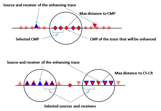
Max Distance To CMP
Maximum distance (in metres) from the output bin CMP location to the CMP midpoint of a raw input trace, for that trace to be included in the partial summation. This is the first stage of trace selection. Larger values gather more traces from a wider spatial aperture, which improves stacking fold and noise suppression but may reduce spatial resolution. Set this value consistent with the expected lateral coherence length of the target reflectors. Default: 150 m.
Max Distance To CS-CR
Maximum distance (in metres) between the source of the output trace and the source of a candidate raw trace, and simultaneously between the receiver of the output trace and the receiver of the candidate raw trace. This is the second stage of trace selection, applied after the CMP distance filter. It ensures that the selected traces have similar source-receiver configurations to the desired output trace, preserving the offset character. Default: 150 m.
Symmetrical aperture
When enabled, the source-receiver selection is performed using a symmetric search: candidate traces are accepted only when both their source AND their receiver fall within the Max Distance To CS-CR radius of the corresponding output-trace source and receiver respectively. When disabled, a less strict criterion is applied. Enable this mode to produce output traces with strictly controlled source-receiver geometry, which is important for amplitude-preserving workflows. Default: disabled.
Use dynamic window
When enabled, the interpolation time window starts at zero and is dynamically expanded up to the value of Interpolation Window Length until at least one non-zero sample is found. This avoids summing all-zero intervals at the top of a gather, which would degrade the output amplitude. Disable this option only if you need a fixed window size regardless of data content. Default: enabled.
Interpolation Window Length
The half-length of the time window (in seconds) centred on the MF-corrected event time within which samples from the input traces are summed. A larger window captures more energy per event but also increases the risk of including neighboring events or noise. Set this to approximately half the dominant period of the target reflection wavelet. Default: 0.010 s (10 ms), minimum: 0, maximum: 1000 s.
Stabilization Window Length
The half-length of the stabilization time window (in seconds) used to compute the normalization energy for the stacked output. A larger stabilization window averages the amplitude over a broader time interval, providing more stable amplitude estimates in the presence of irregular fold. Should be set greater than or equal to the Interpolation Window Length for best results. Default: 0.010 s (10 ms), minimum: 0, maximum: 1000 s.
Write mode
Controls how the output file is opened when the module starts:
Direct — Creates a new output file or overwrites the existing one. The user is prompted for confirmation if an existing file is detected.
Append — Adds results to an existing output file without overwriting previously calculated bins. Use Append mode together with the Calculation area parameters to process large datasets in segments or to resume an interrupted run. Default: Direct.
Max time shift
The maximum allowable MF time correction (in seconds) that may be applied to a raw trace sample before it is admitted into the partial stack. Events requiring a time correction larger than this value are rejected. The default value of 99999 s is effectively unlimited. Reduce this value to exclude events with anomalously large moveout, which may indicate erroneous MF parameter picks or cycle-skipping artifacts. Default: 99999 s, valid range: 0–100000 s.
Calculation area
This group limits which output bins are computed during a given run. It is particularly useful for processing a large 2D line in segments, or for re-running only a portion of the output geometry without reprocessing the entire line.
First bin to calc(-1 no limit)
The sequential index (1-based) of the first output bin to be enhanced. All bins before this index are skipped. Set to -1 to start processing from the very first bin in the output geometry. Default: -1 (no lower limit).
Last bin to calc(-1 no limit)
The sequential index (1-based) of the last output bin to be enhanced. All bins after this index are skipped. Set to -1 to process through the very last bin in the output geometry. The value of Last bin must be greater than or equal to First bin when both are set. Default: -1 (no upper limit).