Assigning Geometry to seismic data
![]()
![]()
The module is designed to assign geometry on land and marine 2D/3D seismic data, check the geometry, and to do trace editing. The trace headers are filled in accordance with an input geometry file without binning (binning will be made on later stage by using Binning2D/3D modules).
The process of geometry assignment is divided into three steps:
1) Loading and QC geometry files using the appropriate load geometry module (Load geometry from ASCII, Load observer log from ASCII, Load geometry from SPS, Load geometry from SEG-P, or Load geometry from UKOOA P1)
2) Geometry assignment (Connect geometry from the Load Geometry and the original file trace headers and SEG-Y data handle)
3) QC, correction of applied geometry and optional trace editing.
Geometry Application is a standalone module, and does not need to be run inside a seismic loop.
Geometry QC Procedure
1) First set-up the geometry application flow. This should include
•Loading Data ( Read SEG-Y Traces or Read Seismic Traces).
•Reading in Navigation (Survey files) with the appropriate Load Geometry module.
•Connect/reference all modules.
2) Set the module parameters.
•If the spread information of input data is in the trace header (i.e.,If you have a SEG-P file), check off “spread from trace headers”.
•Recreate Channels numbers should only be used as a last resort.
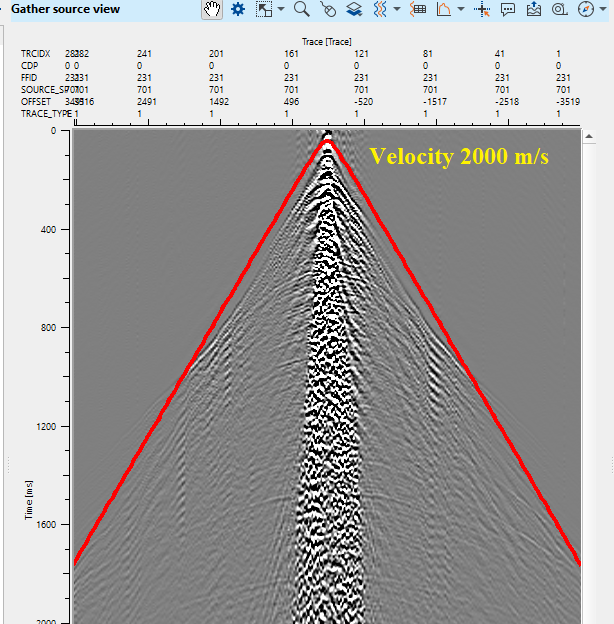
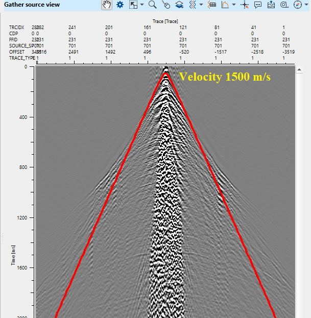
•Velocity – set to an approximate LMO velocity. This is QC tool and will not be applied to your data.
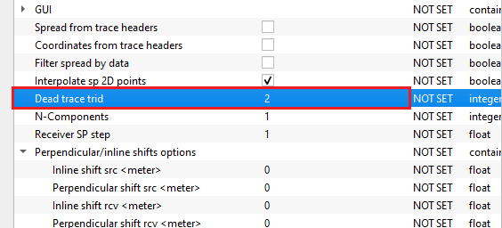
•Dead trace trid – Change this number if the trace ID marker of input data for dead traces is something other than 2.
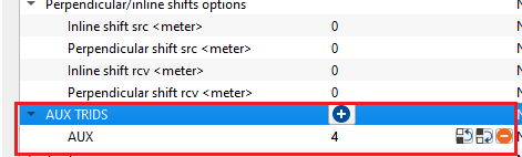
•AUX TRIDs – Some data sets have additional auxiliary traces that are marked with special trace IDs. The user can indicate that here.
3) Display all the Vista groups for the module. There are three basic categories of vistas in Geometry application. Tables, Maps,and Traces.You may click on any entry in a table, or any location in a map, and that point will be highlighted or displayed in all the other views
Table Views
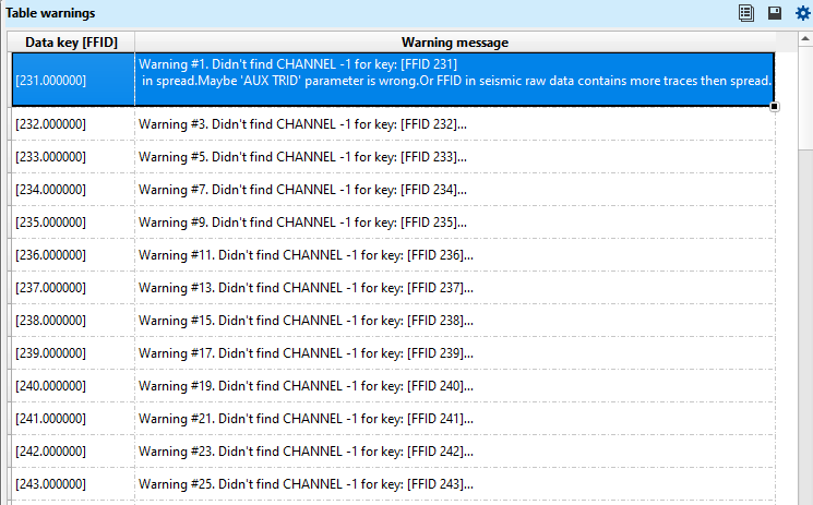
•The Table Errors vista will display mismatches between the original seg-y file and input geometry file. To expand the row, the user should place the mouse pointer at the beginning of the next row line and drag it down. This way, it will expand the row and see all the contents of the warning messages.
•
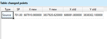
•The Table Changed Points will display points that have been moved, including their new and former/old positions.
•
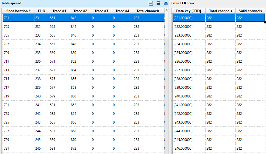
•Table Spread & Table FFID RAW displays the spread and raw FFID information respectively.
•
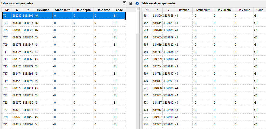
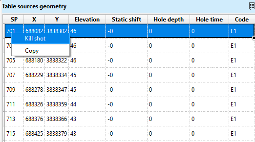
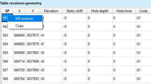
•Table Sources & Table Receivers display the source and receiver numbers and coordinates. The user may kill shots or receivers (mark all the traces as dead) by right clicking on that entry in the table and selecting “Kill Shot” or “Kill Receiver”.
•Table Receivers will be created when the user selects the option "Create receiver tables" inside the GUI parameters. Otherwise, it won't create. Please be cautious with this option as in case of large surveys (like 3D), it takes lot of time and memory.
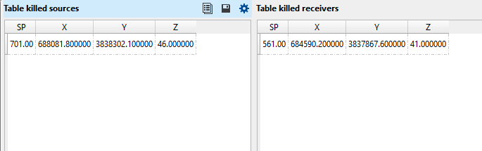
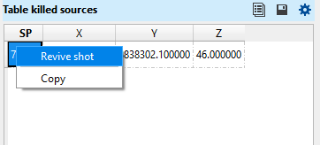
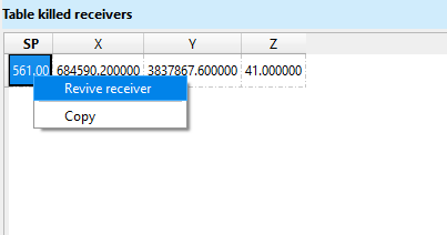
•Table Killed Sources & Table Killed Receivers display all the shots and receivers killed (marked as dead) by the user. Killed shots or receivers can be revived by right clicking on any entry in these tables and select “Revive”.
Map Views include:
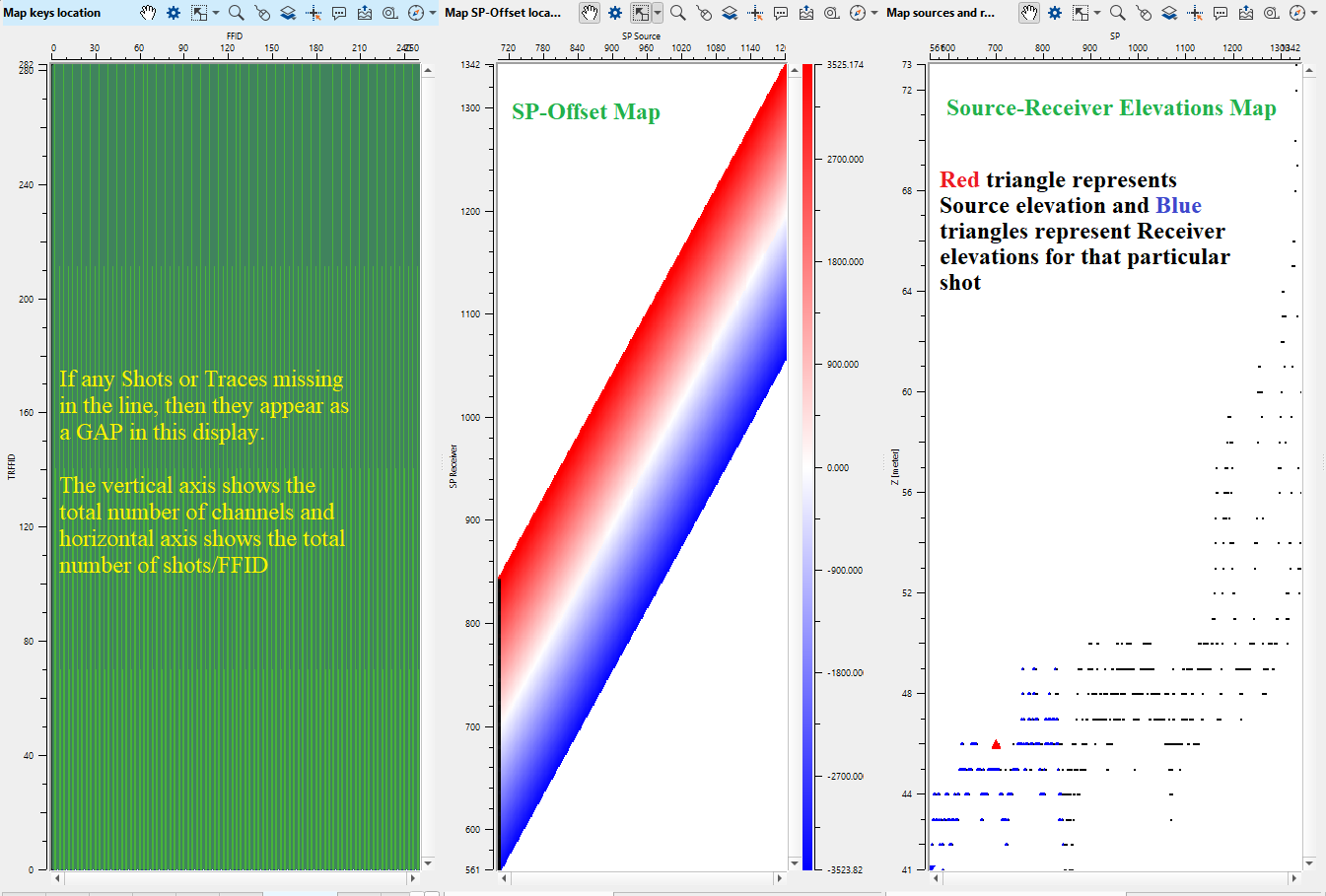
•Map FFID location, Map Sources and receivers elevations and Map SP-Offset location, which display various cross plots of geometry parameters
•Map Sources and Receivers Location, which displays the location of shots and receivers on a map, and allows the user to move those points around if necessary. See Moving Pointsbelow for more information.
Gather Views include:
•Gather FFID, Gather Receiver, and Gather Source, which displays the traces of the current selected FFID, Receiver, and Source. You may edit individual traces in these views. See Trace Editing below for more information.
4) There are now several methods of investigating the input data for geometry errors and mismatched traces. The following are only few suggestions:
1.Use Table Errors Vista to check for mismatches between input geometry files and input seismic data.
2.Use Action Items associated with Geometry application to view the shots, receivers and field files automatically ( FFID slide, Sources slide, Receivers slide) or one by one ( FFID prev, FFID next, Source prev, Source next, Receiver prev, Receiver next).
3.Click on the Map and Table views to view the gathers at those locations.
4.Use Map Sources and Receivers locations and the Gather Source/Gather Receiver views to verify the positions of sources and receivers and move them (see moving points).
5.Use the Trace Editing feature to reverse trace polarities, or mark problem traces as dead
![]() Once the user has performed all geometry edits, DO NOT rerun the Geometry Application module. If the user execute the Geometry application again after the edits, it will overwrite all the edits and the user has to redo the whole exercise again. You are now free to take that data into binning or, to save the result with Save Seismic.
Once the user has performed all geometry edits, DO NOT rerun the Geometry Application module. If the user execute the Geometry application again after the edits, it will overwrite all the edits and the user has to redo the whole exercise again. You are now free to take that data into binning or, to save the result with Save Seismic.
Moving Points
You may move the physical location of a shot or receiver point on the location map using the Map Sources and receivers location.
To Move a Source Point:
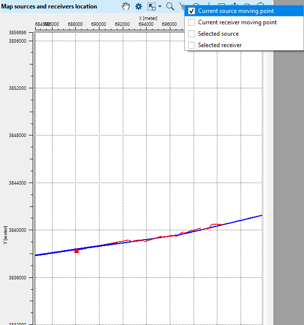
1) Use the ![]() button on the vista tool bar for the Map Sources and receivers location Vista, check off “Current Source Moving Point” and “Selected Source”
button on the vista tool bar for the Map Sources and receivers location Vista, check off “Current Source Moving Point” and “Selected Source”
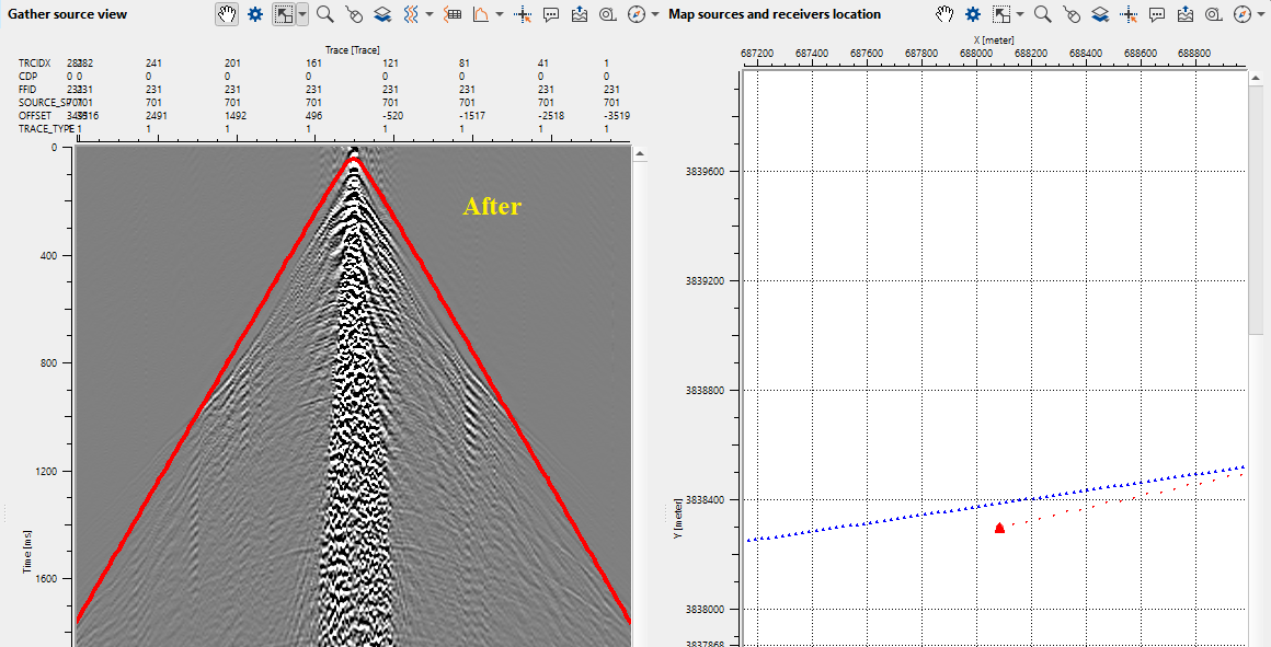
2) Right Click and hold on the Source point you would like to move. Drag the point to its new location. The previous location of the source will be indicated by its original marker (default: Red triangle), and the new location will be indicated by a new marker (by default, a semi-transparent red circle)
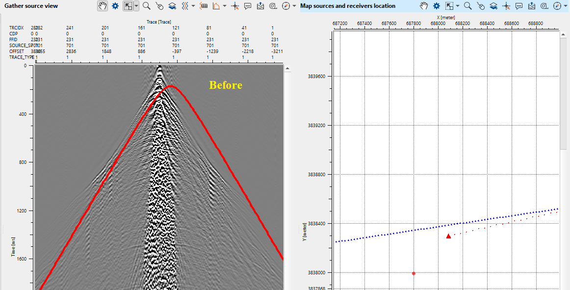
•When moving the Source point, the Velocity displayed on the Gather Source view will update to reflect the new source point location.
•TIP: Try to move the point so that the velocity display aligns with the traces of the Gather view. The peak of the velocity display should match up with the nearest first arrivals – This is a good indication that your source point is positioned correctly
•The source point marker will update with its new location when you click on the new point again, or on a different source point.
•The new position will also be reflected in the Table Changed Sources.
Also, we get the changed positions in a tabular format.
To Move a Receiver Point:
1) Use the ![]() button on the vista tool bar for the Map Sources and receivers location Vista, check off “Current Receiver Moving Point” and “Selected Receiver”
button on the vista tool bar for the Map Sources and receivers location Vista, check off “Current Receiver Moving Point” and “Selected Receiver”
2) Right Click and hold on the Receiver point you would like to move. Drag the point to its new location. The previous location of the source will be indicated by its original marker (default: Blue triangle), and the new location will be indicated by a new marker (by default, a semi-transparent blue circle)
•When moving the Receiver point, the Velocity displayed on the Gather receiver view will update to reflect the new receiver point location.
•TIP: Try to move the point so that the velocity display aligns with the traces of the Gather view. The peak of the velocity display should match up with the nearest first arrivals – This is a good indication that your receiver point is positioned correctly
•The receiver point marker will update with its new location when you click on the new point again, or on a different source point.
•The new position will also be reflected in the Table Changed Receivers.
•
Trace Editing Steps
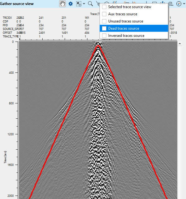
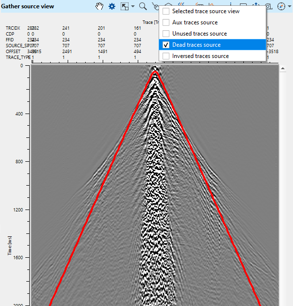
1) Using the ![]() button on the Vista tool bar for the user chosen Gather display (FFID, Shot, or Receiver), select the type of trace marker you would like to set. Make sure only one option is checked off at a time.
button on the Vista tool bar for the user chosen Gather display (FFID, Shot, or Receiver), select the type of trace marker you would like to set. Make sure only one option is checked off at a time.
•To set traces as dead, and remove them from the dataset, choose Dead Traces.
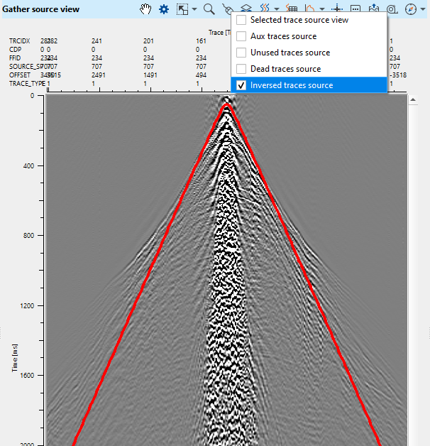
•To reverse the polarity of traces, choose Inversed.
•To set the unused marker, choose Unused.
•To set the Auxiliary flag, choose Auxiliary.
2) To set a marker, right click with the mouse, or right click and drag across several traces
Tip:Go to the Vista properties of the view to adjust the size and color of the trace markers, to make it easier to see which traces are flagged and which are not.
3) To apply those markers to the input data, DO NOT run the geometry application module.
Traces will not be removed or changed until you save the resulting data set using Save Seismic or Save SEG-Y.
To mark any traces as Dead traces, select the "Dead traces source" on the Current source gather window. Next, hold MB1 and drag towards left to right and a line appears horizontally on the Current shot gather window. This will mark all the traces as Dead traces.
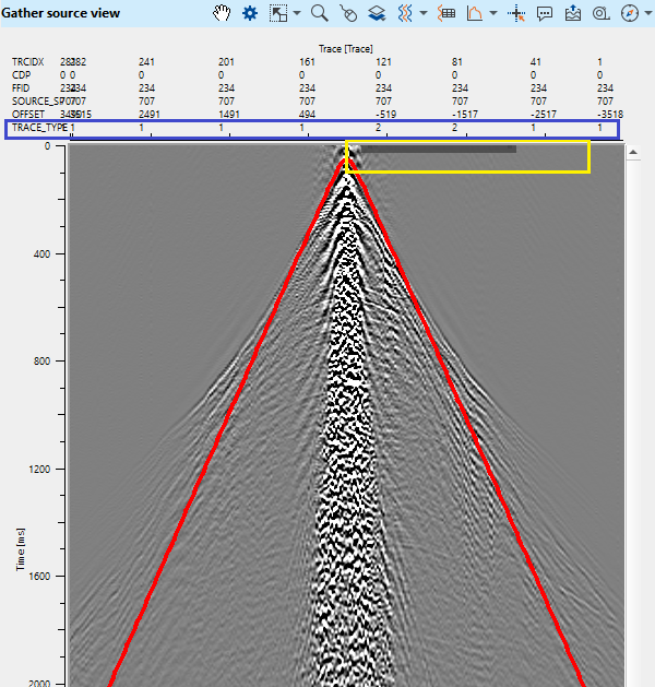
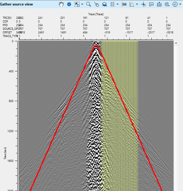
In the below images, if we observe the last/3rd image from left to right, within the yellow rectangle, there is a greyish black line appears. This marks all the selected traces as Dead traces. Also, the TRACE_TYPE for these traces changes from 1 to 2 as shown in the blue rectangle.
To undo these changes, hold MB3 and move from right to left and all these traces will be treated as live traces and changes the TRACE_TYPE will be back to 1.
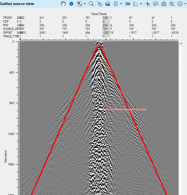
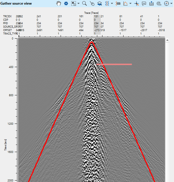
Similarly, to change the polarity of the traces follow the same procedure. To change any traces polarity, first select the "Inverted traces source" from the control item (figure 1, first figure) and hold MB1 and draw from left to right (figure 2, middle figure). For single trace, just select the particular trace. Upon releasing the mouse button, it will mark the selected traces with a mustard yellow color lines (figure 3, last figure).
![]() Once you have performed all geometry edits, DO NOT rerun the Geometry Application module. If the user execute the Geometry application again after the edits, it will overwrite all the edits and the user has to redo the whole exercise again. You are now free to take that data into binning or, to save the result with Save Seismic.
Once you have performed all geometry edits, DO NOT rerun the Geometry Application module. If the user execute the Geometry application again after the edits, it will overwrite all the edits and the user has to redo the whole exercise again. You are now free to take that data into binning or, to save the result with Save Seismic.
![]()
![]()
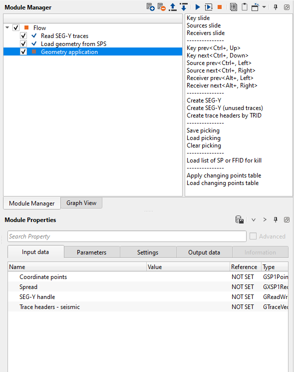
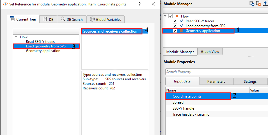
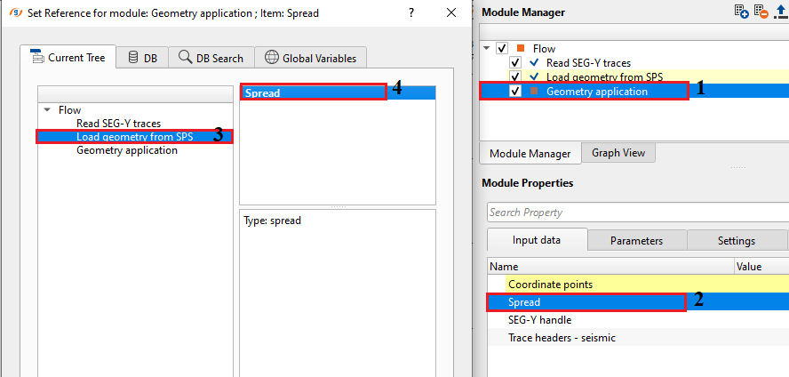
Coordinate points - Connect/reference to input data that contains the coordinate information for both source, receiver and all additional information such as SPS-R, SPS-S, etc. Usually this information we receiver from load geometry from SPS, load geometry from ASCII modules.
Spread - Connect/reference to input data that contains the spread information
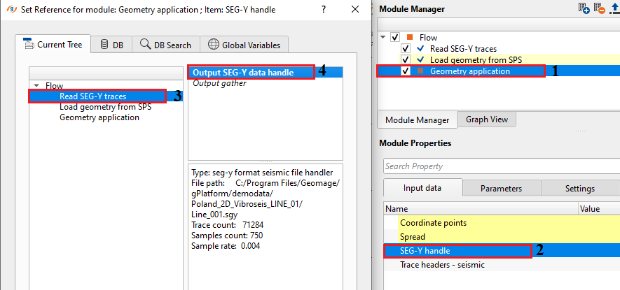
SEG-Y handle - Connect/reference to the Output SEG-Y data handle from "Read SEG-Y traces".
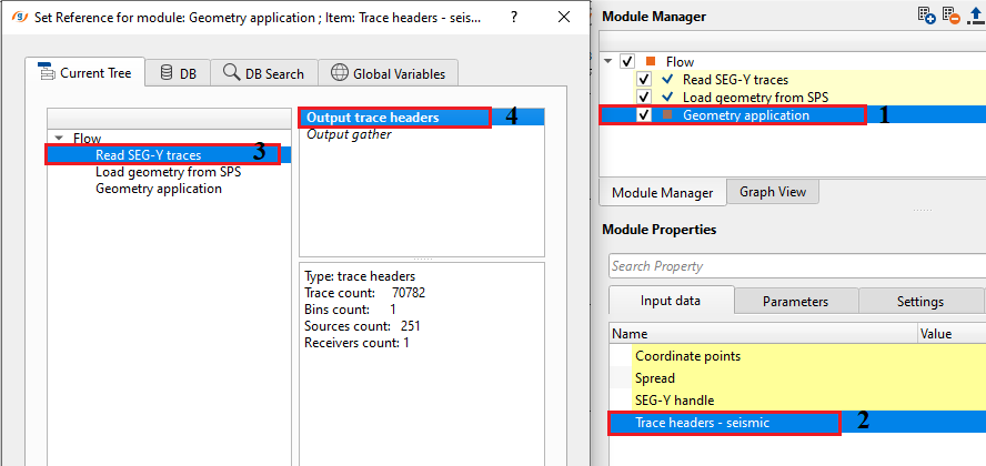
Trace headers - seismic - Connect/reference to Output trace headers of the "Read SEG-Y traces".
![]()
![]()
Velocity - Provide the velocity for theoretical determination of first break arrivals. This velocity line can be used as a QC tool to check the geometry whether it is correct or not.
Recreate data channels numbers - By default, FALSE (Unchecked). If checked, it will overwrite the existing channel numbers and recreates the channel numbers from 1 till last trace of that particular FFID/Shot point.
![]() We recommend not to recreate the channel numbers unless it is required.
We recommend not to recreate the channel numbers unless it is required.
Recreate geom channels numbers - By default, FALSE (Unchecked). If checked, it will recreate the geometry channel numbers when the channel numbers are incorrect/missing. It will start from channel number 1 till the last trace/channel of that particular FFID/Shot Point.
Remove dead traces - By default, TRUE (checked). It will delete/remove the traces flagged as DEAD. It will be identified by the TRACE_ID or TRACE_TYPE.
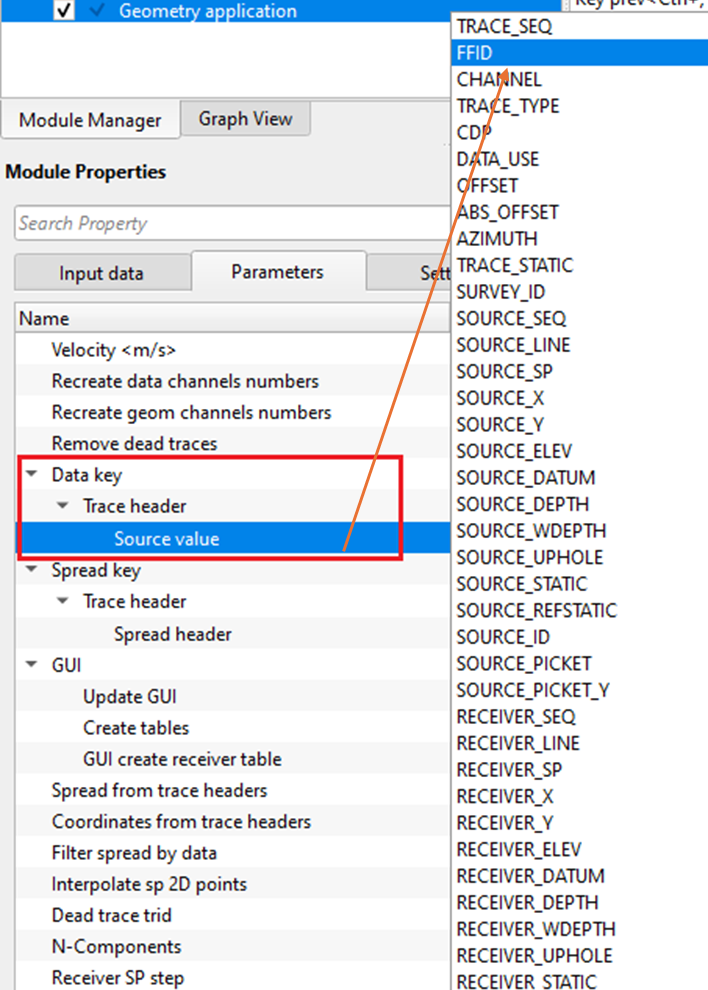
Data key - TIn this section, the user has to select the trace headers of the Data i.e. Raw seismic data. The seismic data trace headers and the navigation data trace headers should be in sync or match to assign the geometry.
Trace header - Select the appropriate Trace header from the drop down menu.
Source value - Select the source value. Usually FFID, SOURCE_SP , SOURCE_SEQ.
Spread key - This section deals with the navigation. User should provide the corresponding trace header.
Trace header - Choose the appropriate trace header from the drop down menu.
Spread header { FFID, SOURCE_SP, SOURCE_LINE, SOURCE_ID, RECEIVER_SP, RECEIVER_LINE } - Select the header.
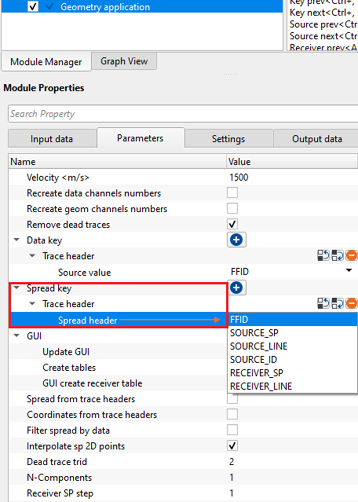
GUI - This section deals with the Graphical User Interface where it creates the Vistas and Tables for visualization and QC purpose.
Update GUI - By default, TRUE (checked). This option updates all the visualization items.
Create tables - By default, TRUE (checked). If checked, this parameter creates source tables.
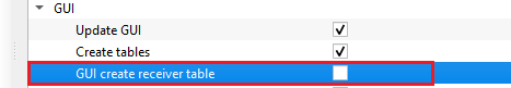
GUI create receiver table - By default, FALSE (Unchecked).
![]() Pay attention to this parameter, if the input data is a 3D survey then checking this option will take lot of memory and time to create the receiver table. It is better to avoid.
Pay attention to this parameter, if the input data is a 3D survey then checking this option will take lot of memory and time to create the receiver table. It is better to avoid.
Spread from trace headers - This parameter gives the opportunity to read the spread information from trace headers. This is especially true when the input data navigation data is SEG-P type. For this kind of dataset, the spread information is already recorded in the seismic trace headers.
UseTraceHeaderX - false - By default, FALSE. If the Spread from trace headers option is TRUE then the user should DO NOT have to provide the spread information at the input data tab.
Filter spread by data - By default, FALSE. When this option is TRUE, it will limit/filter the input data based on the SPREAD information.
Coordinates from trace headers - By default, FALSE. If checked, this parameter gets the coordinates from the trace headers.
Interpolate sp 2D points - It will interpolate the Shot Points in case the input navigation information is not having consistent SP number increment.
Dead trace trid - Provide the dead trace identification number for the traces having zero amplitudes. By default, 2.
N-Components - Define the number of components (In case multicomponent data).
Receiver SP step - Define the receiver SP step size. In few instances, the Receiver SP increases by 2 so the user should pay attention to this and provide the appropriate value.
Perpendicular/inline shifts options
Inline shift src - Provide any inline shift information available for source. This parameter deals with the horizontal displacement of the source along the source line. If the source is moved forward from it's existing distance then the offset changes since the distance between the source and receiver increased thus the time travel from the source to receiver also increases.
Perpendicular shift src - Provide any perpendicular shift information available for source. This parameters with the vertical displacement of the source perpendicular to the source line. This is mostly used in 3D surveys.
Inline shift rcv - Provide any inline shift information available for receiver.
Perpendicular shift rcv - Provide any perpendicular shift information available for receiver.
AUX TRIDS - Auxiliary traces are additional traces which stores additional information. Each survey assigns different auxiliary trace IDs. There may one or multiple auxiliary traces available in a shot gather. Specify all available auxiliary trace IDs by clicking on the  icon.
icon.
Tracking - This parameters displays the information of current FFID, source and receiver number
Source SP - Current displayed Source SP
Receiver SP - Current displayed Receiver SP
Sliding - Parameters for the interactive analysis of seismic data (Source, Receiver in movie mode)
Step - Seismic data step (Source, Receiver)
Delay - Time delay for seismic data visualization
Do not update Source ID - By default, FALSE (Unchecked). If multiple source IDs exists like in marine seismic data acquisition, for a NAZ(Narrow Azimuth) survey, we'll have two seismic sources. So each source will have it's own Identification number like SRC ID 1 & SRC ID 2.
![]()
![]()
SegyReadParams - This section deals with reading of the input seismic data.
Thread count (for SSD) - Total number of threads used to read the data. For by using multi threading, it will be faster. By default, 5.
Bulk size (traces) - Total number of traces to read in a bulk. By default, 5000
Stop after error - By default, TRUE (Checked). This option allows the program to stop it when it encounters any errors.
Skip - By default, FALSE(Unchecked). This option helps to bypass the module from the workflow.
![]()
![]()
Trace headers - updated(live trace only) - Outputs trace headers with only live traces or TRACE_TYPE = 1.
Trace headers - updated - Outputs trace headers with geometry information. It includes all trace types.
Trace headers - spread - Outputs trace headers with spread information only.
Current key gather - Outputs the current selected primary key (Data key) gather.
Current source gather - Outputs current source gather.
Current receiver gather - Outputs current receiver gather.
Table killed sources - Outputs table killed sources. This can be exported as a table by using "Export table" module.
Table killed receivers - Outputs killed receivers table.
Table killed FFID - Outputs killed FFID table.
Table changed points - Outputs table changed points. This table consists of the old and new x & y co-ordinates.
Spread table - Outputs the spread table.
Sources geometry table - Outputs the entire source geometry information in tabular format.
Receivers geometry table - Outputs the receiver geometry information in tabular format.
Table key data - Outputs key data in tabular format. Key data is nothing but Primary key(Data key).
Table warnings - Outputs all the warnings in tabular format.
This module doesn't provide any information so the user can ignore it.
![]()
![]()
In this example workflow, we are reading both seismic and navigation data of Poland 2D by using "Read SEG-Y traces" & "Load geometry from SPS". The outputs from these two modules will be connected/referenced to Geometry application module.
Geometry application module generates lots of Vista items for the user to QC the data. As we described in the earlier chapters of Geometry application, the user have lot of options to QC the data and do trace edits etc.
![]()
![]()
Key slide - Depending on the Data key type (Usually FFID), the data moves to the next data key with a specified key step size in the parameters. This is good animation to go through all the shot records for a quick visualization and QC.
Sources slide - This action item performs to move the source at the user defined key step size.
Receivers slide - This will slides the receivers for a quick visualization of the receiver data through out the line.
---------------
Key prev - Moves the current key (Usually FFID) to the previous key.
Key next - Moves the current key (Usually FFID) to the next key.
Source prev - Moves the current source to the previous source.
Source next - Moves the current source to the next source.
Receiver prev - Moves the current receiver to the previous receiver.
Receiver next - Moves the current receiver to the next receiver.
---------------
Create SEG-Y - This option allows the user to directly create the SEG-Y file. Provide output file name and path. This SEG-Y output consists of all the geometry updated trace headers information and it doesn't include any binning or cmp information.
Create SEG-Y (unused traces) - This action item allows to save the unused traces like auxiliary traces, dead traces etc for further usage. Provide the output file path and name.
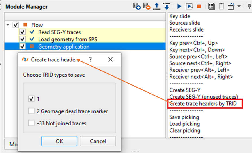
Create trace headers by TRID - This will allow the user to choose which TRID (Trace ID) to be used moving forward. Upon clicking this option, a pop-up opens up with all available TRID. Choose/Check the one required. This is the option which creates the "Trace headers updated (live traces only)"
---------------
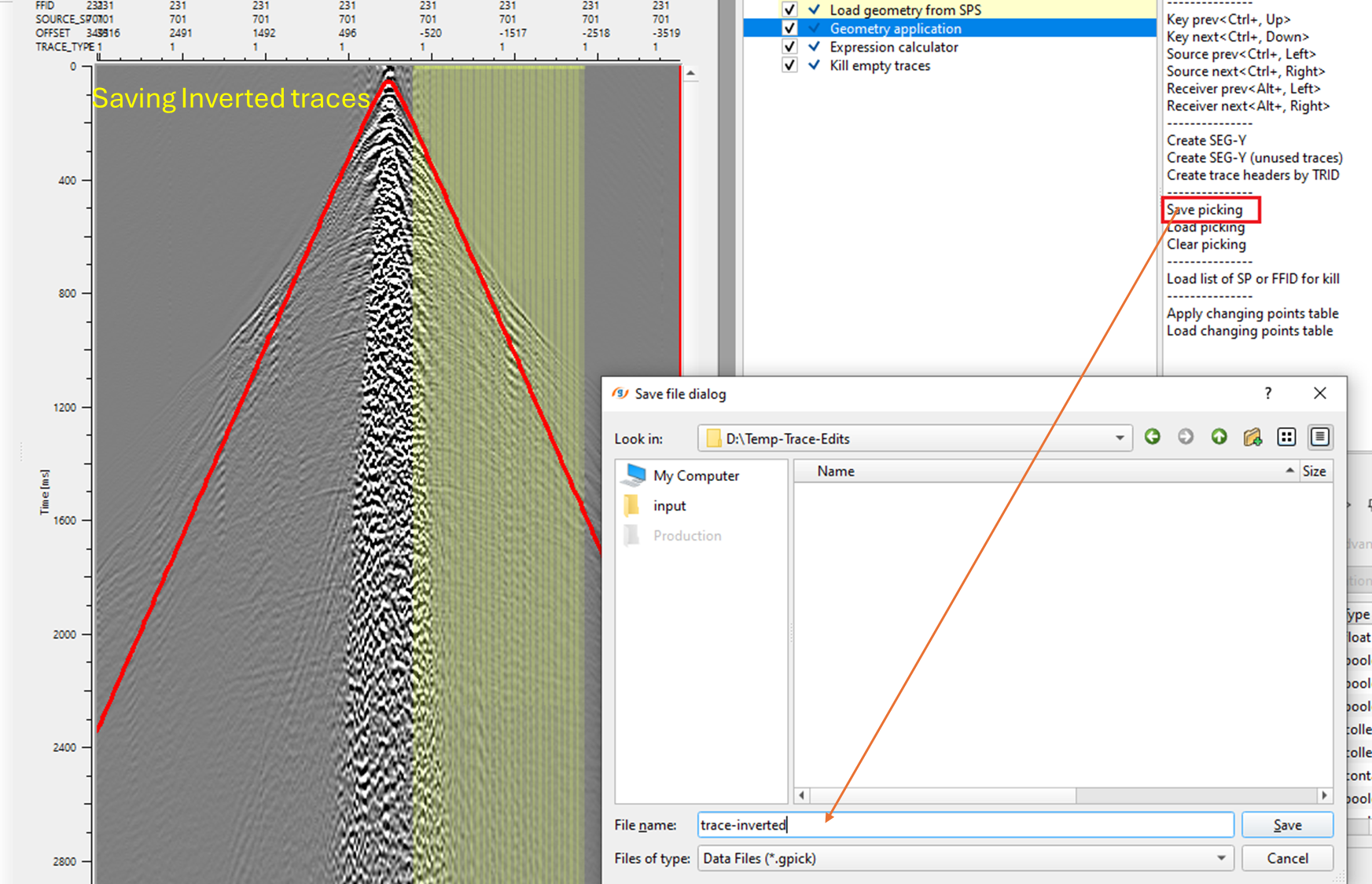
Save picking - These are the trace edits the users performed during the geometry assignment. All the trace edits like marking the dead traces, noisy traces, trace polarity reversal etc can be saved into a file (.gpick extension) for later use.
Load picking - Previously saved trace edit files can be loaded by using this option.
Clear picking - This option allows the user to clear all the edits which includes marking of dead traces, trace polarity reversals etc.
---------------
Load list of SP or FFID for kill - Any text file which consists of the Sources/FFID to be killed can be imported from here.
---------------
Apply changing points table - This options allows the user to update the corrected/modified source/receiver changing positions from it's previous positions. Unless, it is not performed the changes won't take place and won't update the trace headers.
Load changing points table - In case there is an availability of changed points table externally, the user can import the table from here.
![]()
![]()
YouTube video lesson, click here to open [VIDEO IN PROCESS...]
![]()
![]()
Yilmaz. O., 1987, Seismic data processing: Society of Exploration Geophysicist
 * * * If you have any questions, please send an e-mail to: support@geomage.com * * *