Trace header interpolation using Matrix
![]()
![]()
This module reads values from one or more pre-built interpolation matrices and uses them to fill or update specific trace header fields. For each source, receiver, or bin position, the module looks up the corresponding XY location in the connected matrix and evaluates a user-defined mathematical expression to compute the new header value. The result is written into the target trace header field for every trace in the dataset.
A common use case is filling in elevation, depth, uphole time, or statics values that are only sparsely available in the field data. These sparse measurements are first organized into an interpolation matrix using the Create interpolation matrix module, and then this module distributes those interpolated values to every trace header in the dataset. Multiple matrices can be connected simultaneously, allowing complex expressions such as combining or scaling values from different data sources.
Seismic trace headers holds many kinds of information like source & receiver elevations, depths, statics etc. Some of the values are sparse and they may not be available for all the traces due to various reasons. In order to have that information, we extract the information from a matrices and interpolate these values and update the trace headers.
Trace headers are having time, offset, elevation, uphole depth, uphole time etc. These data points are arranged in a matrix i.e. row and columnar format.
![]()
![]()
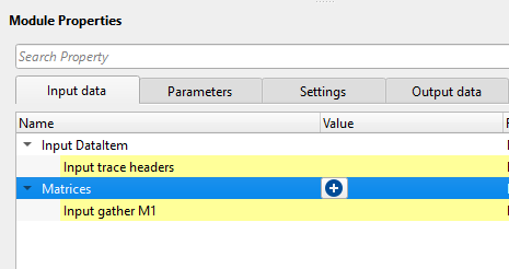
Input DataItem
Input trace headers - Connect/reference to the Output trace headers of any module.
Connect this item to the output trace headers from a preceding geometry or header module. This provides the set of source, receiver, and bin positions that will be used as XY lookup coordinates into the interpolation matrices. All trace header fields that are not explicitly targeted by this module remain unchanged.
Matrices
Input gather M1 - Connect/reference the module which has an interpolation matrix. The user can connect/reference as many interpolation matrix by clicking on the  icon.
icon.
Each matrix connected here is referred to by the variable name M1, M2, M3, and so on, in the order they appear in the list. These variable names are used in the Expression field of the Fill header collection below. For example, if you connect one matrix containing source elevations, it becomes M1 and can be referenced directly in the Expression field. Matrices are typically produced by the Create interpolation matrix module. At least one matrix must be connected for the module to execute.
![]()
![]()
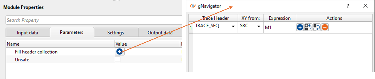
Fill header collection - This parameter let the user to choose which headers needs to be interpolated. Click on icon and it will pop-up a new window. Select the desired trace header from the drop down menu and perform any mathematical expressions if necessary in the Expression field.
Each entry in this collection defines one header interpolation operation. You can add multiple entries to update several header fields in a single execution pass. Each entry contains three sub-parameters described below.
Trace Header — Select the trace header field to be filled with the interpolated value. The drop-down list contains all standard trace header fields (for example, SOURCE_ELEV, RECEIVER_ELEV, UPHOLE_TIME, DATUM_ELEV, and others). If custom header fields exist in the connected trace vector, they also appear in the list. The selected field is the destination where the computed value will be written.
XY from: — Specifies which geometry point is used as the XY lookup coordinate when reading the matrix. Choose SRC to use the source location, RCV to use the receiver location, or BIN to use the midpoint (CMP/CDP bin) location. For source-related headers such as SOURCE_ELEV, use SRC. For receiver-related headers such as RECEIVER_ELEV, use RCV. The module will report an error if the selected XY source is incompatible with the chosen header field. Default is SRC.
Expression — A mathematical expression that computes the value to write into the selected header. The variables M1, M2, etc. represent the values read from the connected matrices at the XY position of each trace point. Standard arithmetic operators and mathematical constants are supported. Examples: M1 (use matrix value directly), M1 * 0.001 (scale by a factor), M1 + M2 (combine two matrices). The default expression is M1. If the Expression field is left empty, that entry is skipped.
Unsafe -
Controls whether the module modifies trace header data in place or on a private copy. By default this option is disabled (unchecked, safe mode), which means the module first creates a full copy of the input trace vector and writes the interpolated values into the copy. This protects any other module that shares the same input data from seeing unintended changes.
When enabled (checked, unsafe mode), the module writes directly into the shared input trace vector without making a copy. This is faster and uses less memory, but any other module that reads from the same input data will also see the modified header values. Enable this option only if you are certain that no other module in the workflow depends on the original unmodified header values and you need to reduce memory consumption or processing time.
![]()
![]()
Auto-connection - By default, TRUE(Checked). It will automatically connects to the next module. To avoid auto-connect, the user should uncheck this option.
Number of threads - One less than total no of nodes/threads to execute a job in multi-thread mode.
This module supports multi-threaded execution. The matrix lookup and expression evaluation for each source, receiver, or bin point is performed in parallel. Increasing the number of threads can significantly speed up processing on large datasets. The default value of 0 means all available CPU cores are used. Set this to a lower value if you need to reserve CPU resources for other tasks running concurrently.
Skip - By default, FALSE(Unchecked). This option helps to bypass the module from the workflow.
![]()
![]()
Output DataItem
Output trace headers - This module outputs the updated output trace headers with the interpolation values.
The output is a complete trace header dataset with the selected fields updated using the interpolated matrix values. All other header fields are passed through unchanged. Connect this output to subsequent modules such as geometry QC tools, statics application, or further processing steps that require the enriched header information.
There is no information data available for this module so the user can ignore it.
![]()
![]()
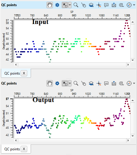
In this example workflow, we are interpolating the source elevations by using two modules.
•First create interpolation matrix where we create the matrix.
•Second, use this matrix to update the trace headers using "Interpolate headers from matrix"
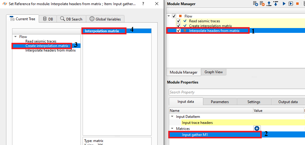
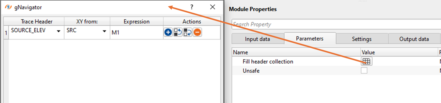
We select the SOURCE_ELEV from the trace headers drop down menu.
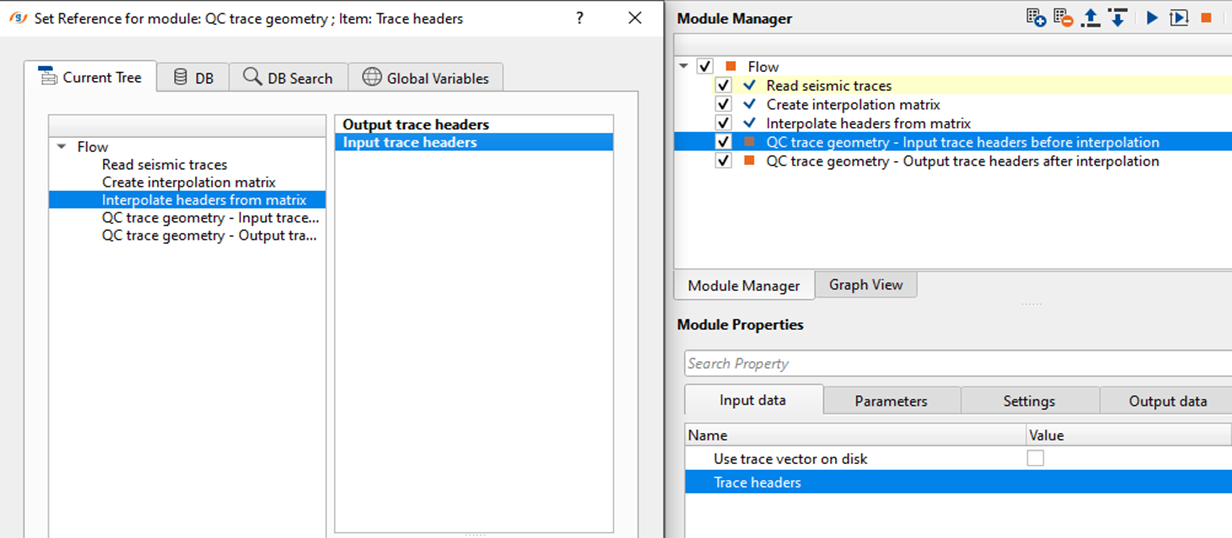
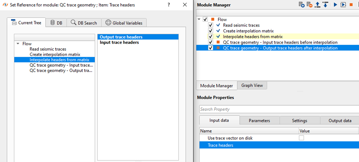
Execute the module. There won't be any Vista items for QC purpose however we can check the output interpolated trace headers by using "QC trace geometry" module. In this we'll add two QC trace geometry modules to our existing workflow and connect/reference the input and output trace headers from "Interpolate headers from matrix" input and output trace headers respectively.
Now, display the QC points of both QC trace geometry module to check before and after interpolation of SOURCE_ELEV trace header values.
![]()
![]()
There are no action items available for this module so the user can ignore it.
![]()
![]()
YouTube video lesson, click here to open [VIDEO IN PROCESS...]
![]()
![]()
Yilmaz. O., 1987, Seismic data processing: Society of Exploration Geophysicist
 * * * If you have any questions, please send an e-mail to: support@geomage.com * * *